AMAZON multi-meters discounts AMAZON oscilloscope discounts
CONTENTS
1--INTRODUCING SIGNALS and FILTERS
Types of filter
Passive and active filters
Digital filters.
2--RESISTORS, CAPACITORS and FREQUENCY
Currents and capacitors
Phase changes
Inductors
Filter characteristics
High-pass filter
Orders
Another view of filters
Project 1--Light-operated lamp
Operational amplifiers
Simple low-pass filter
VCVS filters
Orders of active filters
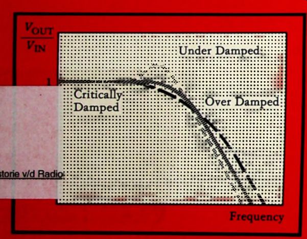
Types of response
Project 2--Simple intercom
Frequency-dependent negative resistors
Project 3--Infrared intruder detector
Q and its relatives
Overlapping filters
Tuned active filters
Multiple feedback filters
State-variable filters
Project 4--Tunable audio filter
Project 5--Audio signal generator
Project 6--Fascinating phases
Switched-capacitor filters
Transmission-zero filter
Project 7--Phaser
Harmonics
Filtering in action
Further modifications
Filtering noise
Project 8--Musical box
Project 9--Rhythm sequencer
Project 10--Electronic organ
Project 11--Electronic guitar
Signal processing
Project 12--Discriminating baby alarm
Choosing capacitors
Designing filters A: Passive RC filters
Designing filters B: Low-pass active filters
Designing filters C: High-pass active filters
Designing filters D: Band-pass active filters
Designing filters E: Notch filters
Designing filters F: State-variable filters
Appendix A--FURTHER READING
Appendix B--PIN-OUTS of ICs
Warning!!
Certain circuits and projects included in this guide involve mains voltages and wiring. These are not recommended for beginners or those with little knowledge or experience of working with mains wiring and voltages.
About this Guide:
Although most books on filters are extremely mathematical--for filters are some of the most mathematically-linked of all electronic circuits--this guide deals with filters in a non-mathematical way. It reviews the main types of filter, explaining how each works and what it is used for. Most sections end with one or more practical projects to illustrate the topics covered in that section.
To help the reader select a suitable project, they are graded in three levels:
Level 1 projects are suitable for beginners, who have a little experience of building projects from kits or from magazine articles. Some books that outline constructional methods are listed in Appendix A.
Level 2 projects are of average standard. After building one or two Level 1 projects, a beginner should be able to tackle some of those at Level 2.
Level 3 projects are more advanced in that their circuits are more elaborate. It is not so much that they are difficult to build as that, if the constructor has made a mistake or fault in their construction, it is more difficult to diagnose what is wrong.
The descriptions of each project include a circuit diagram and a description of how the project works. The components required are specified in the diagram or in a special component list. Except where high-precision (1% or 2%) resistors are essential for the filters, all resistors can be the commonly-used 1/4W carbon or metal film resistors with 5% tolerance. However, it is preferable to use the 0.6W metal film resistors with 1% tolerance, which are available at low cost from some suppliers.
Precision capacitors may be required in certain projects, as explained later.
The circuit diagrams of each project show the pin-out of all transistors used as seen from below. They show the pin numbers for most ICs. An exception is made in the case of those logic ICs which include a number of identical gates.
With these, it does not matter which gate is used in a given part of the circuit. Often the constructor will prefer to use one rather than another, so as to simplify the layout or wiring of the circuit board. The gate inputs and outputs of these ICs have been left un-numbered in the circuit diagrams. Appendix B gives the pin-out of these ICs.
There is scope for modifying and experimenting with several of the projects by incorporating one or more of a range of filter circuits. When designing these filters, refer to the last section, Section 11, which summarizes the main types of filter, with practical design details. This section will be of use also when building filter-based projects other than those in this guide.
This Guide is based on the 1991 BERNARD BABANI (publishing) LTD book by Owen Bishop.
Also see: Understanding Electronics (1984)