by Hans J. Klarskov Mortensen
AMPLIFIER NEEDS three power supplies: one for the filaments (6.3V DC, 2.1A min.), a high-voltage/ low-current type for the B+ of the tubes, and one low-voltage/high current device for the current amplifier (Figs. 3-6).
I will not discuss the various types of high-current power supplies. You must choose what sort of compromise you can live with. The best choice is, of course, to construct a dual mono amplifier. That is straightforward.
Another solution is to use a single power transformer and separate rectifiers and smoothing capacitors. Many audioholics believe this to be the best compromise between economy and performance. But the common return path is a significant compromise.
To make absolutely sure that the least desirable compromise would work satisfactorily, I constructed one proto type which uses a single power supply for both channels. And it does work surprisingly well, maybe because I used two 33,000 uF/75V Mallory smoothing capacitors. Interconnection of this version is shown in Fig. 7.
The schematic also shows some heavy-duty rectifiers across the smoothing capacitors. These prevent reverse voltages across the capacitors and the bias network. High-frequency decoupling is performed on the circuit boards.
The zero connection between the smoothing capacitors should be made of something like a length of one-square inch aluminum or copper, and the central zero connection must be exactly midway between the two capacitor terminals.
The high-voltage/low-current regulator (Fig. 5) is also quite straightforward: a Darlington configured pair of transistors in combination with a zener diode take care of the excessive voltage, while the LM317T takes care of ripple rejection and stabilization. Its noise performance is good: my prototype measured 0.2mV PP of noise (15Hz-250kHz). R3 acts as a current limiter. A smaller value at this point will improve the regulator ’s current capability. The output voltage is given by:
For R5 = 150 ohm and disregarding the last part of the equation you get (ohms):
150 xX Vou) - 187.5 RS = (150 x Vou) -187.5 1.25
R5 should be adjusted so that Voy is 310V ( +-5V).
The tube circuitry will work at a lower B +, but its THD factor and voltage swing will, of course, be increased and reduced respectively.
If you feed the regulator 250V AC (at 100mA minimum), problems should not occur, but please bear in mind that the regulator will need a voltage drop of no less than 12V on load. The tube circuit consumes 10mA/channel (inclusive of the zener-regulators for the front end).
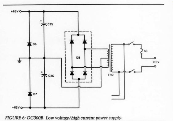
FIGURE 6: DC300B. Low voltage/high current power supply.
PARTS LIST:
LOW VOLTAGE/HIGH CURRENT SUPPLY
C25, 26 10,000 uF/75V (min.) or more
D6, 7 1N5404
D8 400V, 35A power rectifier
Tr2 2x 45V, 500VA transformer
S3 3.15A slow blow
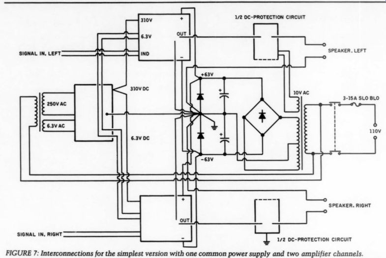
FIGURE 7
Vanilla for Heaters
I decided to use a simple DC supply for the filaments: 6.3V AC (at 2.5A) is rectified by four power rectifiers and a 10,000uF/16V capacitor. Off load, this gives about 8.5V DC; on load, slightly less than 6.3V. With the tubes connected, the voltage will rise slowly from 3.5V, and no shocks will reach the filament. Running tubes at less than the required 6.3V will increase their lives-and it will reduce the open-loop gain of the amplifier very little. For my measurements, I used about 6V on the filaments.
The insulation between the filament and the cathode is made of a thin layer of oxide. This oxide will only stand about a 180V difference between filament and cathode (12AU7, EF86-only 100V). Thus I found it worthwhile to polarize the filament at +65V.
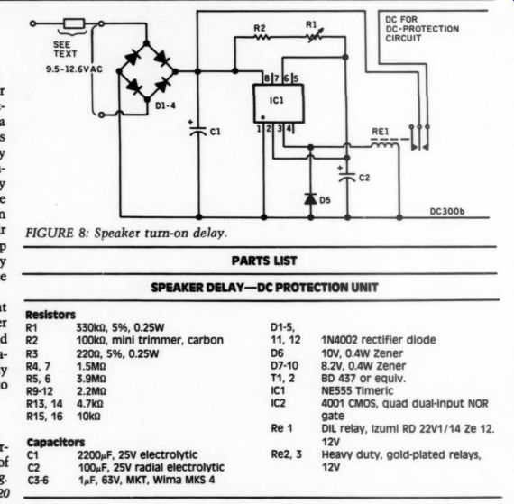
FIGURE 8: Speaker turn-on delay.
--------------------
PARTS LIST
SPEAKER DELAY--DC PROTECTION UNIT
Resistors R1 330k-o, 5%, 0.25W R2 100k-o
R912 2.2m R13,14 4.7k0 R15, 16 10k-O
Capacitors
C1 2200 uF, 25V electrolytic
C2 100F, 25V radial electrolytic
C3-6 1uF, 63V, MKT, Wima MKS 4
D1-5, ‘, 12 1N4002 rectifier diode
D6 10v, 0.4W Zener
D7-10 8.2V, 0.4W Zener ‘2 BD 437 or equiv.
IC1 NESS55 Timeric IC2 4001 CMOS, quad dual-input NOR gate Re 1 DIL relay, Izumi RD 22v1/14 Ze 12.
12v Re2,3
Heavy duty, gold-plated relays, 12v
-------------
Set-up Adjustments
I ’ll describe two procedures-one to be used if you have access to measuring equipment, another if you haven ’t. For both procedures make sure that bias on the gates of the MOSFETs is some microvolts above (SK135) and below (SJ50) zero. If you use the trimmers I suggest in the Parts List, hold the completed circuit board with the tubes toward you, and turn the trimmers clockwise until you hear a tiny click, then counter-clockwise a couple of turns.
1. Complete the amplifier. Connect a dummy load (resistive) to the output and short-circuit the input. Fuse the output stage with small fuses (250mA, slow blow). Connect the oscilloscope in the DC mode to the output, and a millivoltmeter across R29. Apply power to the output stage only. Your instruments should hardly react at all. One little jerk is okay, but nothing more. Wait a short while. Adjust R19 until you read about +9mV on the meter. Adjust the other trimmer (R20) until the scope shows 0.0V. By now the meter will read some thing like 22mV-or rather, the target is to get 0.0V on the output and 22mV across each of the resistors R29-32. This will give approximately 100mA bias through each MOSFET. The current amplifier is now biased. Power down.
Keep the dummy load and the oscilloscope connected, and add a THD analyzer to the output as well. Replace the short circuit on the input with an audio generator. Change fuses to 3.15A, slow blow. Apply power to both tubes and MOSFETs and wait a couple of minutes. Then, apply a signal so you measure approximately 10V PP on the output. Using a I0kHz sine wave, ad just THD by means of R13 until you get as little distortion as possible. Increase input until you get something like - 3dB below visible clipping. Readjust THD by means of R13. This completes your adjustment.
2. If you don ’t have this sort of measuring equipment, you will need a sensitive millivoltmeter, a 22m resistor, and small dummy loads. Complete the circuit boards, but don ’t solder the jumpers marked X, onto the board at this stage. Apply the 310V and the filament power to the circuit board, but no power and no fuses to the output stage now. Short-circuit the input.
Power up. Wait a couple of minutes.
Measure the voltage at Tp4. Adjust R13 so you get approximately 175V here (provided you have 310V on the B + terminal). Find the 22m-O resistor and series connect it with the meter. Measure the voltage between Tp5 and ground, and the voltage between Tp4 and Tp2. Adjust R13 so your readings are exactly the same. You must, of course, keep the resistor in series with the meter all the time even though it is only the Tp4-Tp2 point whose impedance is so high that the artificially increased input resistance of the meter is mandatory. This adjustment of R13 is the only adjustment you need to per form on the tube circuit.
Power down. Dummy load the out put. Put small fuses (300-500mA, slow blow) into the socket on your circuit board. Connect the millivoltmeter (now without the 22 m-O resistor) in parallel with R29 or R30. Power up. Wait a couple of minutes. Your instruments should not react at all. A small jerk is okay, but nothing else. Adjust R19 so that you read approximately 9mV. Now connect the meter in parallel with the dummy load on the output. Adjust R20 so that you now read 0.0V. Return to the source resistors.
The voltage across any one will now be quite near 22mV. Your target is to get as close to 22mV across each source resistor and 0.0V on the output. It may require some patience, but if you use MOSFETs with identical production codes you should not find it too difficult. At this bias level, the tempera ture stability of the circuit is very good indeed.
Power down. Solder the jumpers marked X onto the board. Change fuses to 3.15A slow blow. Remove the short circuit of the input. You are through.
-----------------------------
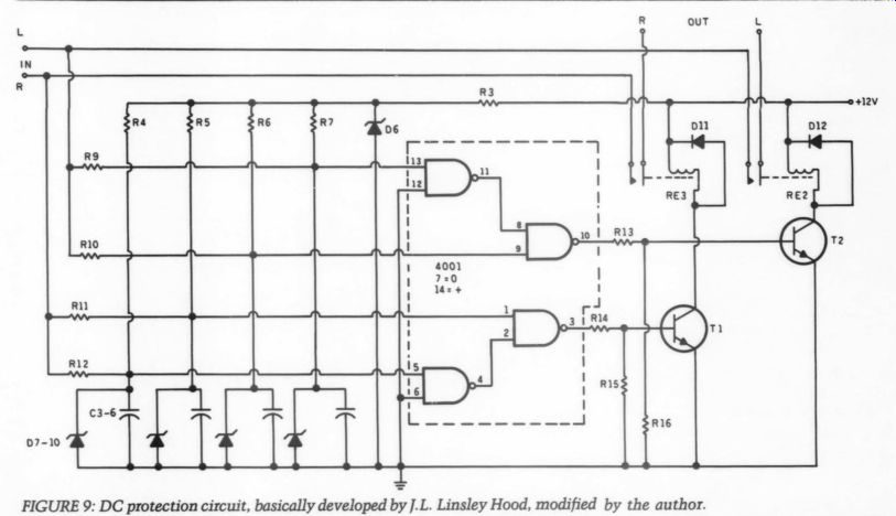
Fig 9
Delay and Protection
To avoid damage to your speakers during warmup, I recommend some sort of turn-on delay. The circuit I present (Fig. 8) has proven reliable and is inexpensive. The timer IC, NE555, will trigger after a time, which is equal to 1.1 x R x C-regardless of the supply voltage (yet 18V maximum).
When NES555 is triggered, the output goes low. For an AC supply we can use anything between 9.5 and 12.6V. You can get this current either from a separate winding on one of the power transformers or from a separate, probably very cheap transformer. Adjust R2 to get a delay of 45 sec. Then you can either let the small DIL relay drive some heavy-duty, gold-plated relays connected to the speaker terminals- or you can include the DC-protection circuit.
The CMOS based circuit (Fig. 9) was developed by Briton John Linsley Hood? I haven ’t come across anything better, so why not stick with the best? The protection circuit reacts to approximately +2V. The integrating time constant, however, was chosen such that it will never react against large musical peaks, but it will turn off the speaker in less than 80usec, if a large DC potential appears. Therefore, if any thing goes really wrong with the amplifier I won't have to rid myself of a heap of black matter which used to be my speakers.
The circuit board for this unit follows international pin-spacing standards, but I have also tried to leave space around the speaker relays to accommodate larger types as well, of course that may also require some board modifications.
Construction
Using the circuit patterns and the stuffing guides, assembly of the beast should not present any problems. Notice that gate components R25-28 and C12, C13 must be soldered to the board on the copper side, as close to the gates as possible. Contact between the sources of the MOSFETs and the circuit board is made with one of the screws that holds the semiconductors in place. Be sure no connection whatsoever occurs between this screw and the aluminum bracket.
Use a sleeve around the screw.
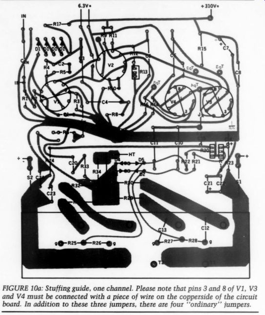
FIGURE 10a: Stuffing guide, one channel. Please note that pins 3 and 8 of
V1, V3 and V4 must be connected with a piece of wire on the copper-side of
the circuit board. In addition to these three jumpers, there are four ‘ordinary
’ jumpers.
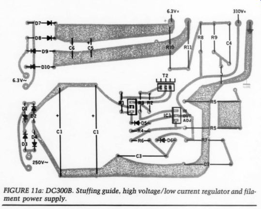
FIGURE 11a.
Heat from the power MOSFETs is transported to a large heatsink (1°C/W, or preferably better) via an aluminum bracket. Use the drilling template when making this (Fig. 13). Make sure the insulation between the transistors and the bracket is nothing less than perfect. The bracket itself must be as smooth as a baby ’s bottom before you install it. Any small grain of metal may not cause a problem for the first several hours of operation, but the constantly changing temperature here may produce trouble in the long run.
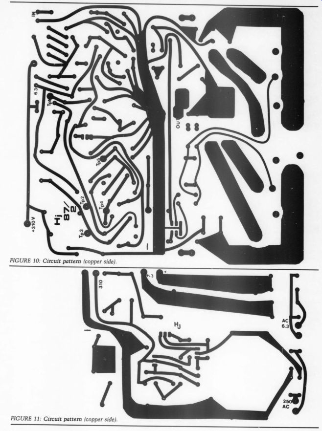
FIGURE 10: Circuit pattern (copper side).
FIGURE 11: Circuit pattern (copper side.)
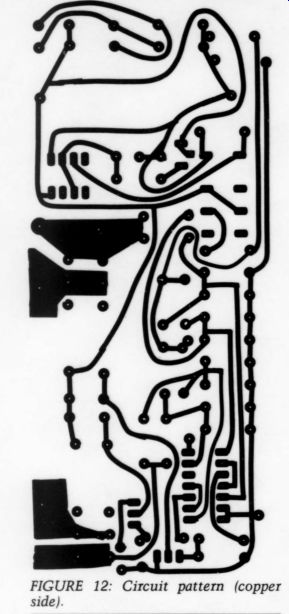
FIGURE 12: Circuit pattern (copper side).
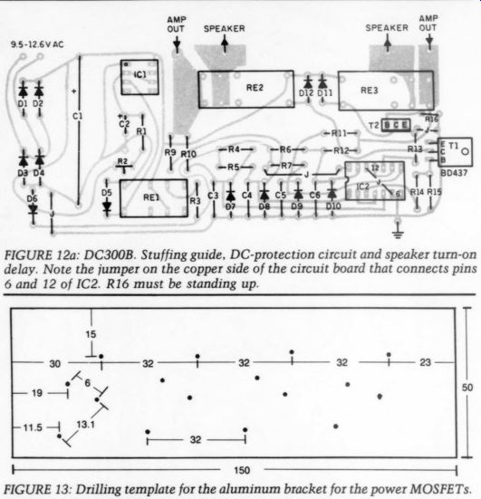
FIGURE 13: Drilling template for the aluminum bracket for the power MOSFETs.
--------------------
TABLE 1 MAIN SPECIFICATIONS
Closed Loop:
Gain
21x, 27dB 34.7V RMS out at 1.6V RMS in =(150W, 80)
Frequency Response
Without filter: -3dB ref. 1kHz, SHz-75kHz With filter: -3dB ref. 1kHz, 5Hz-35kHz
THD
1dB below visible clipping, 80 resistive load:
1kHz: below 0.08% 10kHz: below 0.1%
Damping Factor 1kHZ , 10V RMS into 80 resistive:
63, Z_out = 0.1270
Stability 10kHz squarewave into 80 in parallel with 1uF: stable up to approximately 85V
Signal-to-Noise Ratio
Depends on the practical realization of it.
My prototypes measured better than -70dB ref., 1V, 15Hz-250kHz, unweighted.
Open Loop
Frequency Response
-3dB, 5Hz-25kHz (without RS and C2)
Gain 1kHz, 57dB
----------------------
You may be unlucky enough to come across a very noisy sample of the 12AU7. In my experience one of every 10 or 12 is too noisy to be used in the V2 position. If this happens, you should replace it, or use the noisy device in the V3 or V4 position. The inherent feed back of the White cascode will effectively suppress such noise.
Connections
I have allowed space on the circuit board for an input coupling capacitor, which you should use only if there is risk of DC on the output of your pre amplifier. In such cases, use a 0.220uF/ 400V capacitor, of your preference. If you don ’t need this, solder the input leads directly to the grid-resistor of V1, ignoring the ground connection near the ‘hot ’ input terminal on the circuit board. The input coupling capacitor is labeled on the stuffing guide as C_in; it is not shown on the schematic.
The completed stereo amplifier consumes about 100W idling. Half of this goes to the power MOSFETS, the rest is consumed by filaments, transformers and so forth. Good ventilation is a must. The life of the electrolytic capacitors will be significantly shortened if they get too hot. For the same reason R17, R23 and R24 of the amplifier should be mounted about a half -inch above the board. This also applies to D7-10 of the filament power unit, as well as R5 of the high-voltage regulator.
If you decide to construct the ‘simple ’ version-using the single power supply, you should connect the individual circuit boards as shown in Fig. 7. To get a decent signal-to-noise ratio, be sure the connections between the in put socket and the circuit boards are of exactly equal length, twisted quite firmly together (use 75mm? power leads) two and two, and that the two pairs follow almost the same (short) route through the chassis from socket to circuit board.
Is It Worthwhile?
I may not be the right person to justify building the project, however, trying to be as honest as I can, I believe the mid range and the top end are very detailed, and very soft. Subjectively, individual notes have breathing space. In this sense, it is very tube-like, and despite the wealth of details, the amplifier never sounds overly analytical.
As for the lows, I am a bit more in doubt. On one hand, everything is there, but on the other hand, you should consider using the DC300B with a turntable/cartridge/preamplifier/speaker combination whose bass reproduction tends to be ‘slim. ’ The DC300B is a MOSFET amplifier-but it is, as far as I can hear, far better at controlling the speakers in the low register than quite a number of other MOSFET amplifiers. Like any other amplifier, the DC300B is a compromise-but one I can easily live with. I am sure that it ’ll take quite a number of years before I ’ll consider replacing it.
Quite frankly, it is superior to any tube amplifier I ’ve heard (apart from the OTLs).
Thanks for listening. I wish you many happy hours of music. a Postscript Since I completed this article, I have been fortunate enough to audition the amplifier with quite a number of speaker/preamp combinations. Now I am not so sure about my doubts about the bass performance. The turntable/ arm combination I based this verdict on seemed to make any amplifier play sloppy bass. With my present set-up (Thorens TD125 slightly modified and Rabco SL8 and Ortofon MC20S) there is no sloppiness.
As expected, the DC-protection circuit also protects the loudspeakers against offset voltages on the output, and this does occur about 2dB above clipping level, which means the speakers are disconnected in the event of clipping.
I think the offset voltage above clipping level is caused by minor differences between the source resistors, the FETs, but perhaps mostly by the different Css of the so-called complementary FETs. DC-feedback would of course have cancelled such misbehavior, but as it has a nice side effect and appears above clipping level, I have decided to leave things as they are.
Also see:
A SIMPLE HIGH-QUALITY CD OUTPUT AMP, By Jan Didden
AC SENSING CONTROL, By LB. Dalzell