By Reg Williamson
DESPITE THE CONFIDENT predictions of universal digital recording in the home, whether it be DAT or recordable CD, the ubiquitous Compact Cassette will be around for a long time to come. At the time of writing, pre recorded cassettes still outsell all other media.
It is doubtful whether Philips, the original creators of the Compact Cassette, ever imagined it would take hold as one of the dominant hi-fi pro gram sources in the home and for in car entertainment; and for this, we have to acknowledge the commercial initiative and technical persistence of the Japanese.
I hasten to add, though, no one is going to claim that in terms of absolute fidelity, the Compact Cassette satisfies on all counts. It does not. But as a domestic medium-its sheer convenience and ergonomic near-perfection-most of us will put up with the slightly less than-perfect fidelity.
Someone once asked me to explain how it is possible to achieve the results we expect today, in terms of bandwidth and signal-to-noise ratio, despite all the artifacts that bedevil a slow moving, narrow track analog tape system.
Frankly, I cannot; it is easier to explain how impossible it is in pure engineering terms! Everything is against it. Yet, as the honey bee goes on flying despite being a living contradiction in terms of conventional aerodynamic theory, similarly, the cassette medium works--somehow!
----------------
ABOUT THE AUTHOR
Our Contributing Editor has been designing audio hardware for over 35 years. He has been contributing to TAA since its inception 20 years ago. An engineering executive with the telephone utility ‘British Telecom; ’ in 1985, after over 40 years unbroken service (apart from a short spell in the Army), he decided to take his pension, complete with a medal and citation from the Queen. Now, with his increased leisure time, he indulges his passion for music, good food and wine. However, he also teaches electronics part-time at the University of Keele in Staffordshire, England, attempting to convey to a younger generation some of his enthusiasm for sticky technical problems, which burns as brightly as ever.
---------------
This is not to overlook the obvious:
that the whole technology is right on the edge and it doesn’t take much for the best cassette system to fall below its optimum performance. Ideally, the best hardware should have a well stabilized transport mechanism-and that is not too difficult. It should be a three-head system, so that the replay and record gaps can be designed for optimum performance. And finally, it should have a facility for user adjustment of the bias and record levels, to allow for variations in cassette parameters.
Oh, yes, of course--Dolby B is mandatory. I confess to some personal antipathy to other types of noise reduction for the cassette medium, such as the later Dolby C and dbx. A good complementary noise-reduction system should not let you hear it working, and on this count I have some reservations about every other noise-reduction sys tem offered for the cassette medium. In any case, Dolby B is now well established for home recording and is universal for prerecorded cassettes--and quite rightly, too.
An Aging Sony
I started my tape collection in 1953 and about 1977 I began to collect Compact Cassettes for regular domestic use. The first recorder that began to give consistently acceptable results for me was a Sony three-head machine with adjustable bias and record level. These two features I consider essential, and with Sony ’s built-in calibration oscillators, unique at that time, setting up for the many makes of cassette I tended to use was a dream. It usually took only a few seconds to optimize bias and record level for any particular cassette.
Sadly, my trusted Sony K81 is more than eight years old at the time of this writing and beginning to show its age.
It has declined to yield to my doctoring and I decided to pension it off. Spare parts are, of course, quite unobtainable.
With some regret, I discovered there was no longer any comparable machine with identical facilities. Plenty with three heads-a must-and adjustable bias and record level. Eventually, I settled for another Sony model and immediately missed the internal oscillator calibration facility. One could align it roughly by ear, but being a fastidious engineer, I wanted to do it properly.
Hence, this little project-a dual frequency calibration oscillator.
The technique for using it couldn ’t be more simple, but, of course, adjustment of both the bias and the record level must be easily accessible. One can use it with a two-head machine, but it is tedious! In any case, I know of no two-head machine with bias and level adjustments accessible externally.
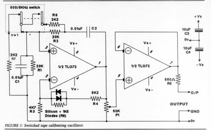
FIGURE 1: Switched tape calibrating oscillator.
Weined and Dined
First, a word or two about the design itself. It is a quite conventional Wein bridge oscillator using a dual op amp integrated circuit (IC). One amp is the oscillator and the other a buffer amplifier with gain adjustment on a preset.
The oscillator, like all Wein bridge designs, uses a form of amplitude stabilization. The ideal is a thermally sensitive device such as a thermistor. But the cost of one, suitable for working at low power, is almost as much as all the other components together.
Another alternative is a device with a positive temperature coefficient, such as a low-current, tungsten filament lamp. However, I could not be sure whether a suitable device would be consistently available to the home builder. In any case, the circuit ’s performance was degraded to some extent by a defect common to all thermal stabilizing devices-*amplitude bounce.
Since very low distortion (THD) is not so essential-the main attribute of thermal control-I tried an alternative; using shunt diodes in a low-current configuration. At the onset of regeneration the output is very high, so the diodes in the degenerative side of the bridge immediately conduct and the amplitude falls. Eventually (actually, it ’s virtually instantaneous) a stabilization point is reached when the bridge balances and the diodes are barely con ducting on peaks, but with most of the negative feedback current going via R3, R4 and R6. The inevitable THD from the presence of the diodes is kept to an absolute minimum, and in the proto type was less than 1% --barely discernible on an oscilloscope.
The advantages are much lower cost-almost any silicon small signal diodes will do-and no bounce, especially on changing frequency. This latter facility is achieved by shunting, via a DPDT center-off switch (or any low power, ganged single-pole on-off pushbutton), two additional resistors across the main components, R1 and R2, in the reactive side of the bridge.
Calculations show that without the shunt resistors, the frequency of oscillation is 159,155/R1 x C1, assuming that both R1, 2 and C1, 2 are equal in value and C is in microfarads. So we get an initial calibration tone of 796Hz.
This is within 0.5% of the design frequency, that of my original Sony at 800Hz. All this, of course, assumes a very close tolerance for the reactive bridge components; I will say more on that.
When the additional 2.2 k-O resistors are shunted across R1 and R2, the combination (R1 x R7/R1 + R7) works out to 1,9820. Using the first sum again, this shows the second frequency is now 8,030Hz; again, within 0.5% of the de sign frequency of 8kHz.
---------------- PARTS LIST
TAPE CALIBRATION OSCILLATOR
Resistors
R1, R2 20k
R3 4.7k
R4 8.2k
R5 5600
R6 1.5k
R7,8 2.2k
Capacitors
C1,2 0.01 uF
C3,4 10uF
D1, D2 1N4148 or equivalent
P1 50k
IC1 TLO72
SW1 DPCO
-------------------------
The exact frequency does not have to be that precise; we simply want a tone roughly in the mid-audio spectrum and another at the high end. For example, if this device were to be used with a good open-reel machine, then I might feel inclined to make the second frequency somewhat higher-say 10kHz.
R7 and R8 would then be 1.6k-O. Ideally, close tolerance values for R1, R2, R7, R8, C1 and C2 should be used; say, 2% for the resistors and 5% for the capacitors. Amplitude parity when the EE eee. ] frequency is switched is much more important, and while close tolerance will normally satisfy this criterion, it can also be achieved by simply matching the values of R1 and R2, R7 and RS, and ideally, C1 and C2 as well, but parity here is not quite so important.
The supply for the oscillator can be from a pair of 9V batteries, in which case the addition of the C3 and C4 is recommended. It can, however, be anything up to + 18V-the maximum B 7 permissible for this IC. Higher supply voltages mean a higher output, with a lower THD content.
So now, how do we use it? First, set the record level control to maximum, then connect the oscillator to both the line inputs via a ‘Y’ cable. Operate the oscillator in the 800Hz mode and ad just the preset on the oscillator board to read zero VU on both channels. Normally, you will not need to alter this.
If your main record control is ganged, some balance adjustment may be needed.
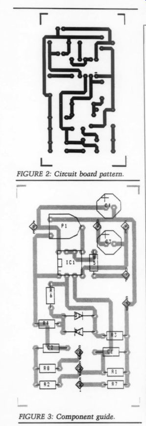
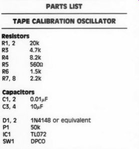
FIGURE 2: Circuit board pattern. FIGURE 3: Component guide.
Now, using the record control, re duce the input level so the level meter reads -20dB below zero VU. Next, run the test cassette in the record mode and monitor the replay output. If the calibration is initially close, the level of the recorded 800Hz will be almost the same as the input level-20dB. If it isn ’t, adjust the preset record trimmers so the replay level is as close as you can get it. By the way, you don ’t have to use the metering facility on the ma chine. If you want calibration ‘on the nose, ’ then monitor with an AC milli voltmeter on the output. Some level meters are, frankly, not good enough for any degree of accuracy.
Okay, now we have record/replay parity. This is essential for accurate tracking of the Dolby B function. Next, switch the oscillator to 8kHz and monitor the input/output parity again.
This time, the 8kHz replay level may be different from the 800Hz. So, adjust the bias trimmer by increasing bias to reduce the tone level, and decreasing it to raise the tone level. And that's it.
However, if the second adjustment is an appreciable one, you would be wise to repeat the 800Hz level adjustment again.
For the final check, record some actual program material and switch be tween input and replay to see how close you have got the preset adjustments.
Now why, someone will ask, do we re duce the level by 20dB? Simply because the record pre-emphasis in the highs would cause saturation and ‘HF crushing ’ if the calibration level were too high, and your readings would be misleading. For this reason, it is also wise to make this adjustment with the Dolby noise reduction off-but don ’t forget to switch it on again!
ACKNOWLEDGMENTS
Many thanks to colleague, Dr. Peter Grannell at Keele University, England, for his valuable comments.
Also see:
A SIMPLE HIGH-QUALITY CD OUTPUT AMP, By Jan Didden
AC SENSING CONTROL, By LB. Dalzell