by HERB FRIEDMAN
Let a little LED light up your power control circuit! A control voltage of only 3 VDC can handle up to 5 Amps!
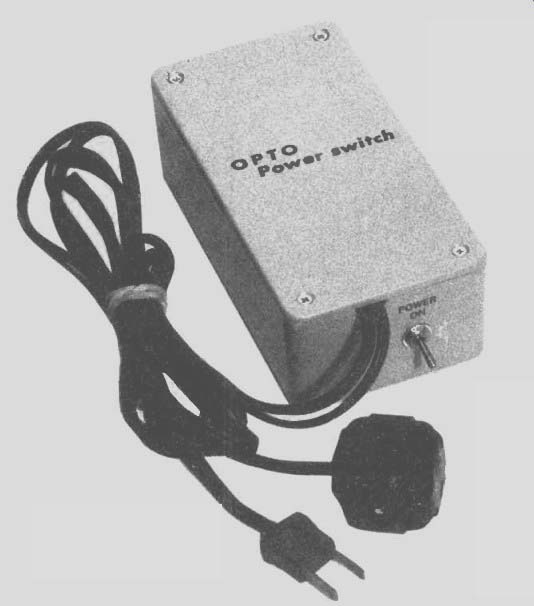
THE OPTO POWER SWITCH IS AN ALL-ELECTRONIC REMOTE Control for a 117-volt power-line outlet(s) that provides total isolation between the control voltage and the power line. The control voltage can be any voltage that provides a nominal control-circuit current of 12 to 20 mA. This can be a DC voltage equal to or greater than 3 VDC (which can be supplied by two ordinary flashlight batteries), or an AC voltage that will provide a minimum "average" value of 3 VDC after full-wave rectification.
Because of the low control voltage control wires don't need any special attention, and they can be run "in the open." Normally, there is no need to enclose the control wires in pipe or conduit (check local electrical codes first, they may vary). The control wires deserve the same attention given to bell circuit wiring.
A typical application would be as a signal device for one of the new garage-door openers, which provide a 24-VDC output when the door is open. The 24-VDC and the Opto Power Switch can be used to turn on an outdoor warning light when the door opens, or a building-mounted "open door" floodlight. Another application might be remote control of an attic fan-or other appliances-when it isn't feasible to run Romex or BX cable through the house.
Essentially, the Opto Power Switch functions as an electronic switch, with the major advantage being no connection of any kind between the control and controlled circuits.
Even if the switched 117-volt power line circuit literally "blows up" there will be no effect on the control circuit.
How it works
The "heart" of the device is the integrated circuit opto coupler MOC3010, IC-1 in the schematic diagram (Fig. 1) It consists of an LED (Light Emitting Diode) and a light-activated DIAC (bidirectional TRIAC control diode) in a half-mini-dip package. The DIAC is connected as TRIAC Q1's gate-control element in a conventional TRIAC circuit.
With an AC voltage applied to the TRIAC via the series-connected power line and load (through socket S01), the TRIAC will turn ON when the DIAC conducts, and OFF when the DIAC stops conducting.
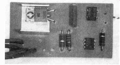
-------- THE ENTIRE CIRCUIT EXCEPT FOR THE CONNECTORS is assembled
on a small printed-circuit board. Note the use of a heat sink under the
TRIAC controller. It is small because it serves only as a protection (safety)
device and is not generally required (see text for details).
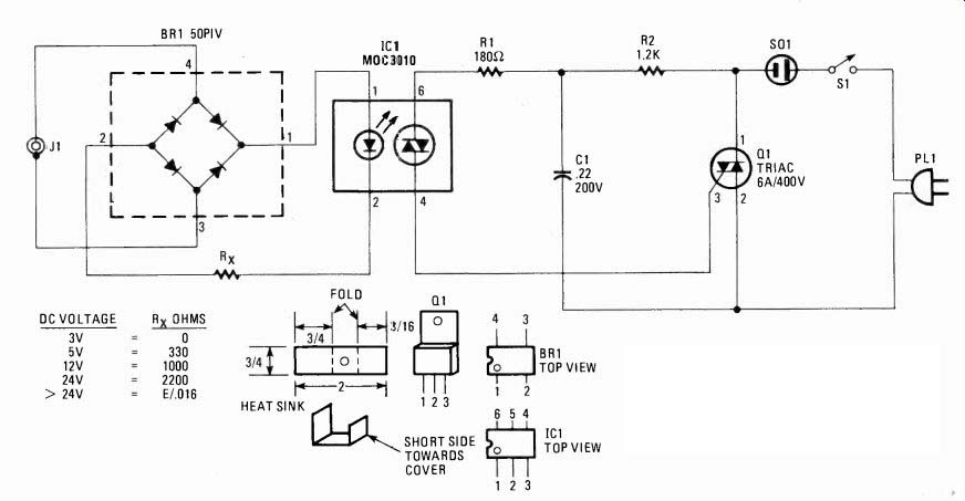
FIG. 1--THE OPTO POWER SWITCH is a simple solid-state device. Follow the
schematic diagram carefully and be certain that no AC wiring is "touchable."
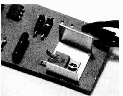
-------- THE HEAT SINK IS POSITIONED SO THE SMALLER FLANGE is
nearest the cabinet cover when the assembly is in the cabinet.
The DIAC conducts, turning on Q1, whenever the internal LED is lit, and it is the "control voltage" that turns the LED on and off.
The control voltage is applied through full-wave bridge-rectifier BR1. It automatically provides the correct polarity to the LED regardless of the polarity of the control voltage at jack J1. Since BR 1 will also convert an applied AC voltage to DC, AC can also be used as the control voltage.
The control voltage must provide between 12 and 20 mA to the LED. Slightly less than 12 mA will cause the circuit to slightly "dim" the AC through the load. Substantially less than 12 mA won't turn the AC power circuit on. More than 20 mA might lead to early failure of the LED. Resistor Rx limits the current through the LED to a safe value for the specific control voltage used. The chart in Fig. 1 shows the required value of Rx for some common voltages. If you want to directly control the circuit with a battery, substitute a short-circuit for R, and use two series-connected 1.5-volt cells. Three volts is the minimum control voltage that can be used. Less than 3 volts will not provide enough illumination from the LED for "full" operation of the DIAC-TRIAC. Take note that there is no error in the chart of resistor RX's values. Below 24 VDC, we must allow for the "loss" produced by bridge-rectifier BR1 (the voltage drop across each of two diodes). Calculated values using Ohms Law which don't include a "fudge factor" for BR l's "loss" will not equal those of the chart. Use the values shown in the chart when the control voltage is less than 24 VDC. For an applied voltage greater than 24 VDC use the formula shown, which assumes an LED circuit of 16 mA. The circuit shown will handle resistive (lighting) loads of up to 500 watts, and inductive (motor) loads of about 350 VA. These are "safe" values that will produce little heat dissipation in TRIAC Q1. We have included a small heat sink in the project-as shown in the photos. It is a protective device, needed only if your control voltage does not fully illuminate the LED. This would result in the TRIAC not conducting for the maximum AC cycle, and would produce some heating in Q1. The heat sink will dissipate the excess heat during the short period it should take you to realize "something's wrong." Build your own Nothing is critical. You can make virtually any layout changes you would like as long as no part of the 117-volt power line circuit can be touched by the user (or anything else), and there is no connection between the power line and the control circuits. Don't attempt to derive the control voltage through a resistive "step down" from the 117-volt power line. This would create a "common" connection between the top circuits. Always use a line isolated low-voltage transformer.
The unit shown in the photographs is assembled on a small printed-circuit board that slips into the PC "card" slots molded into the sides of a Radio Shack 270-223 plastic Project Case. The PC board drops into the slots and is secured when the plastic case cover is secured. No metal or contact from the 117-volt power-line circuit is exposed on the cabinet.
A full-scale template for the 23 31/32 X 1 9/16 inch PC board is shown in Fig. 2. A parts-layout diagram is in Fig. 3. The cabinet isn't a precision moulding and you may have to file the ends of the PC board in a sort of trapezoid shape to fit. To keep filing to a minimum, cut the PC board to the dimensions inside the template's outline; don't cut directly on the outline or on the outer edge of the outline.
The heat sink is made from a small aluminum scrap that can be salvaged from a cabinet, or a chassis panel, etc. To keep unnecessary heat away from the cabinet cover the sink is asymmetrical, with the small end positioned nearest the cabinet cover. The dimensions are shown in Fig. 1. Just make certain that the edge of the sink doesn't touch any of Q1's leads.
The specified BR1 has a notch molded into one end. It is correctly installed when the notch faces the nearest PC-board edge. I C1 has a dot molded into the case opposite pin " I . " It is correctly installed when the dot faces the nearest edge of the PC board.
TRIAC Q1 is secured to the PC board with No. 3 or No. 4 hardware. The leads must be pre-shaped by bending them at right angles to the body of the TRIAC before securing Q1 to the board. Don't try to fasten QI to the PC board and then bend the leads into the holes.
TRIAC Q1 is specifically a non-sensitive type with a gate current of nominally 25 mA. Don't substitute a TRIAC with a more sensitive gate as it will most likely "burn out". The resistor and capacitor values are specifically for the low-cost "general-purpose" TRIACs; they will not accommodate sensitive-gate TRIACs. In this circuit high gate sensitivity doesn't have any effect on performance.
Take special note that capacitor C1 must be rated for 200 volts. In this day and age many capacitors that are job-racked or blister-packaged are "low voltage", often rated for 10, 15, 25, or 100 volts. Even a 100-volt capacitor isn't adequate in a 117-volt circuit. Get the right component the first time.
The least expensive power connection-SO 1 and P L1-is an ordinary AC extension cord available at hardware stores.
Use one about 6 feet long. Cut it at the center and connect the section with the plug as PL 1 and the section with the socket as SO1. The wires from the PC board to the plug and socket can be passed out of the cabinet by simply filing a slot in the top edge of the cabinet on one end.
Control Jack J1 can be anything that matches your existing equipment. S1 can be any SPST switch. If you want to save a few cents you can eliminate S1 and simply connect a jumper across the switch connections on the PC board.
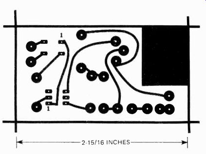
FIG. 2--FULL SIZE FOIL PATTERN makes the printed circuit-board easy to
build from this template.
-+-----------
PARTS LIST
RESISTORS
All resistors 1/2-watt
R1-180 ohms
R2-1200 ohms
Fix-See chart in Fig. 1
CAPA CITOR
C1--0.22 µF, 200 volts (see text)
SEMICONDUCTORS
BR1-Bridge rectifier, 50 PIV, Radio Shack 276-1161 or equal
IC1-Opto Coupler, MOC3010 01-400 volts, 6A. TRIAC, Radio Shack 276-1000 or equal
MISCELLANEOUS
J1-See text
S01/PL1-Extension cord, see text
Cabinet, PC materials, etc.
-------------
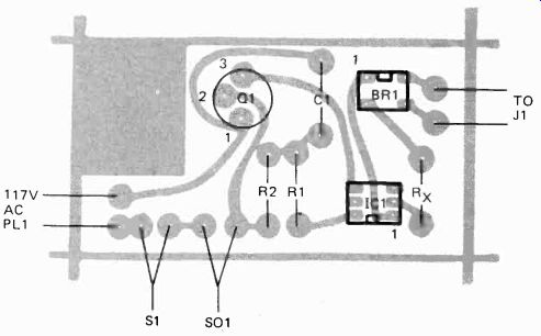
FIG. 3-PARTS-PLACEMENT DIAGRAM. Be sure you have polarity (positioning)
correct for BR1, IC1, and Q1.
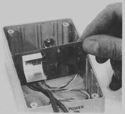
--------- THE PC BOARD ASSEMBLY SLIPS INTO SLOTS molded into the
specified cabinet. It should slide in. If it's a force fit, file the
edges of the PC board until the board drops into the slots.
Final checkout
Do not connect the control voltage to jack J1. Connect a 117-volt lamp to socket SO1 and connect PL1 to an AC outlet. Nothing should happen. The lamp should not light. If it does light you have made a wiring error or have a defective component. Now apply your DC control voltage to J1 . The lamp should light. If it doesn't, connect a DC milliammeter in series with one of the wires to J1 and note the current. If it is zero, check your connections and the installation of BR1--AFTER PUL LING THE POWER CORD (don't depend on S1). If the meter reads between 12 and 20-mA, check for a wiring error from IC1's output through to SOI. If you are using an AC control voltage make certain it provides 12 to 20 DC mA to the LED in IC1. You must connect the meter in series with the diode. If you use the PC construction, the easiest place to make the measurement is in series with resistor R.
THE AC-POWER- LINE WIRES PASS THROUGH A NOTCH cut into the end of the cabinet. They are secured when the cabinet cover is in place.

------- THE WIRES TO CONTROL JACK J1 ARE ON THE FOIL SIDE of the PC
board.
They are tack-soldered to the foil pads.