Source: Radio Electronics--Electronic Experimenter's Handbook (1993)
by JOHN F. KEIDEL
How good is your amplifier? Our inexpensive THD analyzer will let you know.
HAVE YOU EVER WONDERED EXACTLY how good an amplifier is, or whether it actually measures up to the manufacturer's specification of its Total Harmonic Distortion, or THD? Or are you curious if the amplifier you've designed is better or worse than a store bought one? If the answer is yes to any of those questions, then you should build our inexpensive THD analyzer. You can use it to test "home-brew" amplifier breadboard circuits or commercial equipment such as stereo receivers, preamps, and power amps. The analyzer uses an ultra-pure 1-kHz test signal to measure THD at a user-selected voltage level for voltage amplifiers, or a desired power level for checking power amps up to 600 watts. It will detect THD levels down to 0.005 percent! It features a built-in one-percent THD calibrator, a full array of input and output processing controls, and uses your digital multimeter (DMM) as a readout device.
Circuit description
As shown in Fig. 1, an NE5534N low-noise, low-distortion op-amp, IC1, is configured as a Wien Bridge sine-wave oscillator. Carefully matched RC values (R2-C1 and R3-C2) in the frequency-selective positive feed back network contribute to its low distortion level. Resistor R1 and bulb LMP1 form the stabilized negative feedback net work that provides a constant-amplitude output signal. DC off set control R4 keeps DC current out of LMP1, which minimizes second harmonic distortion con tent. Filter network R6-C6 further reduces any residual distortion. After passing through fixed and variable attenuators, plus a buffer amp (IC2), the signal emerges at output jack J1.
The output signal from J1 drives the input of the device under test (DUT), usually an amplifier.
The DUT's output, which includes some degree of distortion, is applied to the input of the analyzer at jack J2. The fundamental frequency (1 kHz) is then re moved from the output signal of the DUT, leaving only harmonic distortion components.
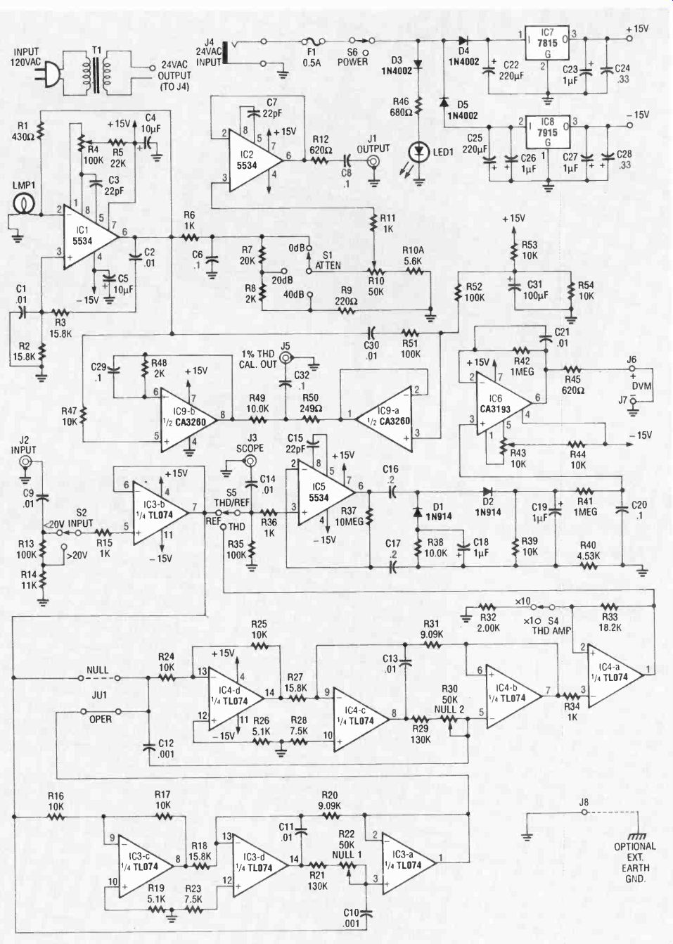
FIG. 1-SCHEMATIC DIAGRAM of the simple THD analyzer. An NE5534N op-amp
(IC1) is configured as a Wien Bridge sine wave oscillator. Carefully matched
RC values in the frequency-selective positive feedback network contribute
to the low distortion level.
Resistor R1 and incandescent bulb LMP1 form the stabilized negative feedback network that provides a constant-amplitude output signal.
Combination notch/high-pass filter circuits IC3 and IC4 (both TL074's) perform the removal function. One feature of IC3's three-stage RC active filter is that it maintains a constant 45-dB notch depth over its full tuning range. The filter is connected in series with an identical second filter (IC4), to provide a 90-dB notch of the fundamental signal.
The resultant frequency response of the combined filters is 27 dB down at 20 Hz, which helps suppress 60-Hz hum and other low-frequency noises.
Above the 90-dB notch frequency, the response is flat ( ± 0.5 dB) from 2 kHz to 100 kHz.
When S4, the THD/REF switch, is in the THD position, a signal containing only THD components is channeled through from the output of the x1/ x10 THD amp (IC4) to the input of the AC-to-DC converter, IC5. Although both polarities of the applied signal are rectified by this circuit, only the positive averaged signal is fed to the low-pass filter R41-C20. The output buffer, IC6, is a CA3193 precision op-amp, stable enough to provide accurate volt, millivolt, and microvolt DC level output signals to an external DVM.
Dual op-amp IC9, a CA3260, serves as a calibrator. The first stage affords precision half-wave rectification of the master oscillator's signal. That same applied signal is AC coupled by C30 to the second stage, biased at 1/2 Vcc, for linear transfer to its out put. Voltage divider R49-R50 mixes a very small portion of half-wave output at pin 7 of IC9 with a much larger full sine wave seen at pin 1. Since the signal swings slightly more positive from its quiescent level than it does in the negative-going direction, it is considered to have a specific amount of second harmonic distortion. That amount, by design, is one percent.
Wall transformer T1 feeds half-wave power diodes D4 and D5 through connector J4, fuse F1, and power switch S5. Capacitors C22 and C25 are the principal filters for the positive and negative supplies, respectively. Smaller filters, C23 and C27, along with high-frequency transient suppressors C24 and C28, are included at the output side of regulators IC7 (a 7815 +15-volt regulator) and IC8 (a 7915-15-volt regulator).
Construction
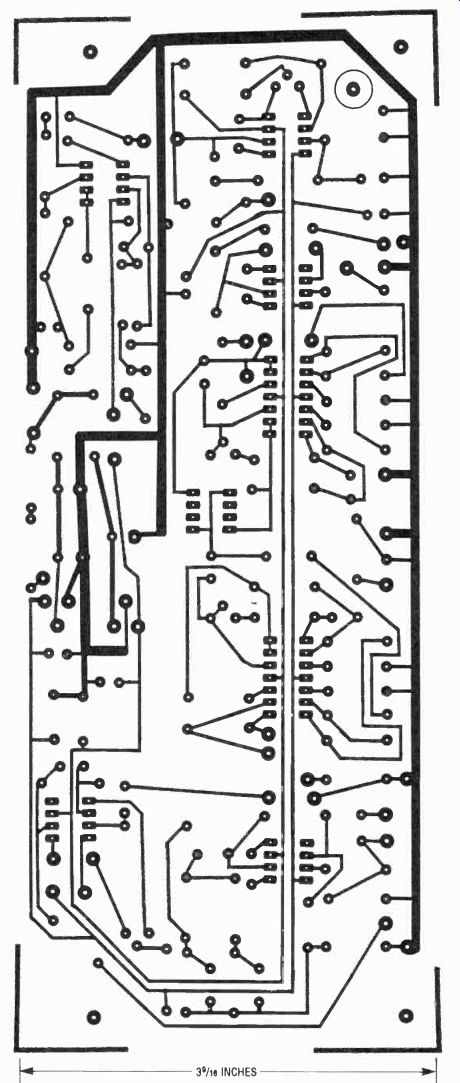
-------- FOIL PATTERN for the THD meter shown actual size.
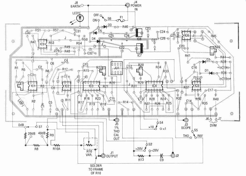
FIG. 2-PARTS PLACEMENT DIAGRAM.
Note that JU1 is actually an 8-pin DIP socket in which a jumper is placed in either the far-left or-right side (see text). Also note the six components soldered to the front-panel-mounted controls.
Breadboard assembly of the analyzer is not recommended, al though a seasoned builder may wish to attempt it. It's best to either make your own PC board from the foil pattern we've provided, or order one from source mentioned in the parts list.
Mount all components as shown in Fig. 2. Check orientation of all polarized parts as you install them, and the use of IC sockets is suggested. All power-line wiring, including the LED1 indicator, uses two wires plus a shield. Connect the shield wires together and then to ground, to prevent hum pick-up. Also, ground the frame of potentiometer R10. Bare ground wires for each BNC connector may be wrapped around the connector body prior to installing the retaining nut. The ground binding post (J8) on the rear panel provides an optional, external earth-ground connection when measuring microvolt-level THD signals. Just connect J8 to circuit ground. The grommet used to hold bulb LMP1 should have a 1/4-inch inside diameter. It is glued to the top side over the hole for maximum resiliency.
In addition to the components that are soldered to the circuit board, also note that five resistors and one capacitor are soldered across the terminals of panel-mounted controls S1, R10, S2, and J2 (see Fig. 2).
Capacitors C1 and C2 must be matched to better tolerances than their marked 1% values. If you don't own or can't borrow a capacitance meter, you can build and use the simple circuit shown in Fig. 3. Adjust the calibration potentiometer with any one of the four 0.01 uF capacitors (C1, C2, C11, or C13) inserted as Cx, to read 1.000 volt on your DMM's 2-volt DC range. (You can consider the reading to be 0.01000 µF.) Now measure the remaining three capacitors and select the two that are closest in value. Absolute value is not important; we simply want them to be the same value. However, if one capacitor measures 80 pF lower than an other, you can solder an 82-pF mica capacitor on the underside of the PC board in parallel with the selected capacitor. The left over 1% 0.01 ILF capacitors can be used for C11 and C13 without having to be closely matched.
Likewise, resistors R2 and R3 must be close in value. Using your DMM on its 20K resistance range, select two 15.8K resistors that are the closest in value. If the match is less than perfect, solder a small-value resistor in series with the lower value to raise it to the exact value of the higher one.
You can mount two resistors in place of one by putting one through each hole in the board and soldering the raised ends together. Again, the leftover 1% 15.8K resistors can be used for R18 and R27 without having to be closely matched.
==========
PARTS LIST
All resistors are 1/4 watt, 5%, unless otherwise indicated.
R1-430 ohms R2, R3, R18, R27-15,800 ohms, 1%, metal film R4-100, 000 ohms, PC-mount potentiometer R5-22,000 ohms R6, R11, R15, R34, R36-1000 ohms R7-20,000 ohms R8, R48-2000 ohms R9-220 ohms R10-50,000 ohms, panel-mount potentiometer R10A-5600 ohms R12, R45-620 ohms R13, R35-100,000 ohms R14-11,000 ohms R16, R17, R24, R25, R38, R39, R49-10,000 ohms, 1%, metal film R19, R2&-5100 ohms R20, R31-9090 ohms, 1%, metal film R21, R29 130,000 ohms R22, R30-50,000 ohms, PC-mount potentiometer R23, R28-7500 ohms R32-2000 ohms, 1%, metal film R33-18,200 ohms, 1%, metal film R37-10 megohms R40-4530 ohms, 1%, metal film R41, R42-1 megohm R43-10,000 ohms, PC-mount potentiometer R44, R47, R53, R54-10,000 ohms
R46-680 ohms R50-249 ohms, 1%, metal film R51, R52-100,000 ohms, 1%, metal film
Capacitors
C1, C2, C11, C13-0.01 µF,100 volts, 1% Mylar C3, C7, C15-22 pF, 300 volts, mica C4, C5-10 µF, 25 volts, tantalum C6, C8, C20, C29, C32-0.1 µF, 50 volts, Mylar C9, C14, C21, C30-0.01 µF., 50 volts, Mylar C10, C12-0.001 µF, 100 volts, 1% Mylar C16, C17-0.2 µF, 50 volts, Mylar C18, C19, C23, C27-1.0 µF, 25 volts, tantalum C22, C25-220 µF, 50 volts, electrolytic C24, C28-0.33 µF, 50 volts, Mylar C26-1 µF, 50 volts, tantalum C31-100 µF, 25 volts, electrolytic
Semiconductors
IC1, IC2, IC5-NE5534N low-noise op-amp IC3, IC4-TL074 quad low-noise op-amp IC6-CA3193E precision op-amp IC7-7815 positive 15-volt regulator IC8-7915 negative 15-volt regulator IC9 CA3260E dual MOSFET-input op-amp D1, D2--1N914 diode D3-D5--1N4002 diode LED1-Red light-emitting diode
Other components
S1-Panel-mount, 2-pole, 6-position switch S2, S4-S6-Panel-mount miniature SPDT toggle switch S3-Not used JU1-8-pin DIP socket or jumper block T1-120VAC/24VAC, 200 mA wall transformer J1-J3, J5-Panel-mount male BNC connector J4-Coaxial power input jack J6-J8-Panel-mount binding post LMP1-Incandescent bulb, #327 Fl-Fuse, 0.5A, 120 VAC
Miscellaneous:
Project case (Jameco Electronics H2507), two 1/2 inch diameter instrument knobs, seven 8-pin IC sockets, (not including JU1), fuse holder, LED bezel, grommet, shielded cable, wire, solder, hardware, etc.
Note: The following items are available from Instrumex, P.O. Box 490, Blue Bell, PA 19422:
Etched, drilled, and plated PC board and silk-screened plastic front panel (both to fit case mentioned above-$25.00 + $3.00 S&H PA residents must include 6% sales tax.
Allow 2-4 weeks for delivery.
==========
You may wish to build your own enclosure for the THD meter.
A silk-screened front panel measuring 9 3/4 inches wide by 3 inches high can be purchased from the source mentioned in the parts list. If you decide to purchase the front panel, and build your own enclosure, build it to fit the front panel and drill several ¼-inch holes in the top panel near the voltage regulators to allow heat to escape. Otherwise you can purchase the same enclosure used for the prototype; the exact model number is listed in the parts list, and the front panel is designed to fit it perfectly. Figure 4 shows the completed prototype.
Adjustments
Using a DMM on its millivolt-DC range, connect it between pin 6 of IC1 and ground. Adjust R4 for a reading of 000.0 mV on the meter. Next, set the INPUT switch (S2) to ">20V," the THD AMP switch (S4) to " x 10," and the THD/REF Switch (S5) to "THD." With the DMM still set to read millivolts DC, connect its leads across the + and- DVM binding posts (J6 and J7) and adjust R43 for a reading of 000.0 mV on the meter.
Filter-null adjustments may be made with an oscilloscope or DMM on its lowest AC voltage range (typically 2 volts). Insert a jumper in the JU1 jumper block (NULL-OPER) in the left-most position when facing the front panel (next to R22, or the "null" position). Connect a short coaxial cable between OUTPUT jack J1 and INPUT jack J2. With power on, and S2 in the "<20V" position, S4 in the x 1 position, S5 in the "THD" position, and the rotary ATTEN-DB switch (S1) and VAR potentiometer (R10) in the mini mum attenuation position, or fully counter-clockwise.
Connect a scope or voltmeter to the IC4-pin-7 side of R31, and connect the ground lead to any ground in the area. If you're using a scope. set VOLTS/DIV switch (on the scope) to any position between 5 and 50 mV/div.
Carefully adjust potentiometer R30 for the best null on a scope screen, or lowest reading on a meter.

FIG. 3--HERE'S A ONE-IC CAPACITANCE TESTER used to match C1 and C2. See
text for details.
Munger the test probe to the IC3-pin-1 side of R20. Adjust R22 for a minimum reading on the scope CRT or voltmeter. Insert the jumper previously placed in the NULL position in the C12 side of the JIM jumper block. You may be able to squeeze 1 or 2 dB more null from the system by shifting the DMM to the DVM binding posts (J6 and J7), setting the meter to its 200 mV DC range, setting S4 to x 10, and trimming the adjustments of R22 and R30.
Checkout and use
Connect a scope or DMM scat to read AC volts to output jack J1.
Rotate S1 and R10; the output signal voltage should vary accordingly. The controls are attenuators, not gain controls, so maximum signal occurs in the counterclockwise position.
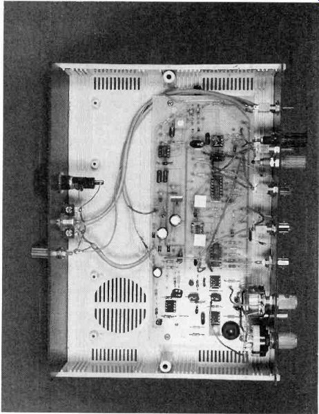
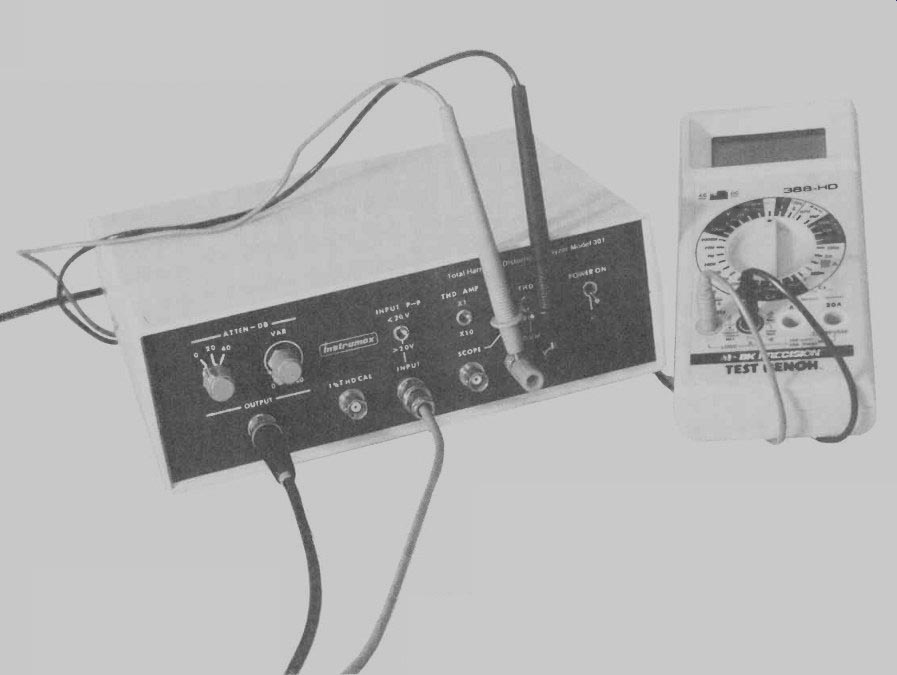
FIG. 4--THE COMPLETED PROTOTYPE. Notice how the incandescent bulb (LMP1)
is protected from damage by a rubber grommet.
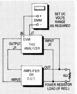
FIG. 5--BLOCK DIAGRAM OF TEST set up. Most THD measurements can be made
in this manner.
=====
THD MEASUREMENT
When a pure or undistorted sine wave is applied to a circuit containing vacuum tubes, transistors, or op-amps, which is used to provide linear transfer of the signal, some degree of distortion always appears at the output.
As the near-perfect sine wave travels through the device under test (DUT), its shape is altered due to inherent non linearities within the circuit. Waveform alteration is the equivalent of adding harmonics, or multiples of the fundamental frequency, in varying phases and amplitudes to the fundamental signal. It can be shown mathematically and by measurement that these spurious harmonic components are vested within the output signal's waveshape.
Spectrum analyzers are used to sweep over the frequency range of interest, separating the fundamental and its harmonics into individual signals. It provides a CRT display of these various signals, including odd and/or even harmonics in their proper amplitudes and frequency locations relative to the fundamental. Similar instruments use digital signal processing techniques rather than a sweep method to provide more in-depth data including phase angles.
Wave analyzers are essentially tuned filters that include a measurement window that is manually frequency shifted through the range of interest. It offers meter-read out amplitude measurements of the various harmonics relative to the fundamental frequency.
THD analyzers are used to notch out the fundamental from the DUT's output signal leaving only the harmonic components intact. It then measures the sum total of the residual signals in terms of their RMS or average values, and compares them to the overall amplitude of the output signal which is taken as a 100 per cent reference. The ratio of the THD measurement to the reference, multiplied by 100, equals the percent THD.
=====
Check the INPUT P-P switch S2 by applying the signal from J1 to J2, setting S5 to "REF," and measuring the AC output at J3. The output signal should be maximum with S2 in the <20V position and minimum in the >20V position. It's important to note that if the input signal to J2 goes much higher than 20V peak to peak, and S2 is in the <20V position, clipping will begin to occur.
You can use the analyzer's calibrator to check all remaining functions. Connect a coaxial cable from J5 to J2. Set all toggle switches to the upright positions, and connect your DMM to J6 and J7 set to read DC volts or millivolts, as required. Now, if the THD signal reads 24.0 mV, which is 0.024V, and you switch the S5 to "REF," the DMM should then read 2.40V, or a number very close to that. When the resulting fraction (0.24/2.4) is multiplied by 100 it should produce a THD percent figure of one percent.
Figure 5 shows the test setup for THD measurements. Say that we are measuring percent THD of a 50-watt amplifier that's connected to an 8-ohm power resistor load. By ohms law, it will take 20 volts across 8 ohms to produce 50 watts. Now let's say we drive the input of the amplifier with a 1-volt pure sine wave and we obtain the 20 volts required at the output. Since 20 volts RMS is 56 volts peak-to-peak, S2 must be set to >20V.
With S5 in "THD" position a reading of 1.4 mV (0.0014V) DC is obtained. In the "REF" position we read 2.00V. Always read the range on the DMM that affords the best resolution. Now make the calculation: 0.0014/2.00 X 100 equals 0.07 percent THD.
Voltage amplifiers are measured in the same manner, but without the requirement of a load resistor. Such amplifiers will probably show lower THD voltage readings. If the THD voltage is too low on the DMM's mV range, set S4 to " x 10." In this case, however, divide the displayed THD voltage by 10. For example, 0.8 mV on the meter is read as 0.08 mV, since it was amplified 10 times to 0.8 mV.
If the measured THD percent is three times or more greater than the analyzer's measurement "floor," no correction of the measured value is required. If it's less than three times, a good approximation of the true THD percent is given by the formula D (DUT) = VD2 (measured)-D2 (floor).
That means if you measure a pre-amp's THD at 0.005%. and the measurement floor is 0.004%, the true THD of the preamp is 0.003%.
Depending upon the depth of the notch and how closely the RC's in the oscillator's frequency selective network are matched, the "floor" should typically be 0.003 to 0.005%. You can check the "floor" value in the same way you measured the 1% THD calibrator, explained earlier. Instead of using the calibrator signal, feed in a maximum signal level from output J1. If you use the x 10 position, it may be necessary to connect J8 to an external earth ground.
Finally, you should know that THD measurements above 10 percent are less accurate than those below 10 percent. since the reference includes distortion plus the fundamental--not just the fundamental.