The name, 3-way portable, refers to a type of receiver which operates on AC, DC, or batteries. These portables were very popular until transistor receivers came onto the market. But the 3-way portable has several advantages over the transistor receiver and will perform better in certain applications.
Among its advantages is the fact that it has better sensitivity and greater output power than comparably priced transistor receivers. It can also be operated continuously from the 120 volt AC lines, thus saving the battery, a feature available in only the highest priced transistor units.
Although transistor receivers have taken over completely for portable use out-of-doors, the 3-way portable is still an extremely popular receiver to be carried about the house.
Batteries for the 3-way portable are expensive compared with those used in transistor radios, so most owners of 3-way portables do not use them on batteries. The technician, however, will continue to see many of this type in his shop, primarily for repairs on the AC/DC power-supply section. For this reason, a detailed discussion of this section follows.
CIRCUIT ANALYSIS OF POWER SUPPLY
All models use a special series of tubes designed to operate with very low filament current and voltage, and having directly heated cathodes. The filaments are intended to operate on DC, and there are no separate cathodes--electrons are emitted directly from the filaments. The filament-current rating is 50 ma, and the filament voltage is 1.4 V DC. The audio output tube, a 3V 4, has a 2.8-volt center-tapped filament so that it can be operated at 2.8 volts and 50 ma by using the series connection, or it can be used with 1.4 volts at 110 ma if pins 1 and 7 are tied together, placing the two sections of the filament in parallel. The series connection is the one most often used.
A basic power-supply circuit is shown in Fig. 7-1. The transformerless half-wave rectifier and R/C-type filter are familiar from Section 2. C4 is a line bypass capacitor to keep out RF signals present on the 120-volt AC lines. R1 is a surge resistor and usually serves as a fuse, preventing damage to the rectifier when a short causes excessive B+ current to be drawn. A selenium or silicon rectifier is always used instead of a tube, and the B+ voltage output is from 90 to 100 volts at the point indicated in the illustration.

Fig. 7-1. Power-supply circuit of a 3-way portable receiver.
Because the tube filaments must operate on DC, a portion of the B+ output is used to supply current for them. R3 is a drop ping resistor for this purpose. It is always a wirewound unit of at least 10 watts. Its value will vary slightly in different models, even though the same tubes are used. This is because there are different values of B+ present at the output filter capacitor in different receivers. In Fig. 7-1, the value of R3 is calculated as follows : Total filament voltage required between pin 7 of 3V 4 and ground is the sum of all the filament voltages in series :
3V4 1U4 1U5 1R5 2.8 volts (series connection)
1.4 volts 1.4 volts 1.4 volts 7.0 volts total
If the B+ at the output filter is 100 volts, then R3 must drop 93 volts:
100 - 7 = 93 volts
The current drawn by the tube filaments in series will be 50 ma, so:
93 volts = 1860 h 50 ma 0 ms
In most commercial circuits, the value of the resistor is based on a voltage of from 7.5 to 8.5 volts at pin 7 of the 3V4. This voltage range is to allow for changes in B+ due to line-voltage variations. For battery operation, a 7.5- or a 9-volt filament battery is used.
Figure 7-1 shows the power changeover switch which changes the operation from AC/DC to battery. This switch is usually operated by a lever which can be moved only when the AC line plug is inserted in a special receptacle on the chassis.
This arrangement prevents the batteries from being connected when the AC line is being used. A great many different switch circuits will be found. In some models, the switch also changes connections in the filament line to place some of the tubes in parallel. A double-pole, on-off switch is frequently used.
C3 is a filter capacitor across the filaments to remove excessive ripple from the filament voltage. This capacitor is usually from 100 to 200 mfd with a DC working voltage of 25 volts.
It may be connected between ground and pin 1, 5, or 7 of the 3V4. If it is connected as shown in Fig. 7-1 and should develop a short, the 3V 4 filament will burn out because the entire filament-line voltage of 7 to 8 volts will now be present across the tube. However, this connection may have an advantage over connecting the filter to pin 7, where a shorted unit would result in damage to the power supply.
The two paths of current through the filament supply are shown in Fig. 7-1, with R4 shunting the filament line for the purpose of providing a separate path for cathode current. If, through some malfunction, the plate current of the 3V 4 were to increase greatly, R4 would prevent a large increase in the current drawn through the filaments of the other tubes. R4 in series with R3 also forms a voltage divider from B+ to ground, preventing the voltage across C3 from becoming excessive when the receiver is operated on AC with the filament line open due to a burned-out tube. Without R4 in the circuit, there would be no current through R3 and no drop across it, putting the full B+ across the capacitor.
OTHER CIRCUIT DIFFERENCES
Certain circuit complications arise because the filaments of the tubes are also the cathodes, and the voltage from the filament to ground is also the cathode bias for the stage. In the 3V 4 circuit, this filament-to-ground voltage can be 7 or 8 volts positive and, if the control grid were returned to B-, the tube would be cut off. Fig. 7-2 shows a typical model with the power changeover switch eliminated for simplicity. The 3V 4 grid can be seen to return to the junction of the 1U4 and the 3V4 filaments, a point which is just 4.5 volts positive. If there is 8 volts at the 3V4 filament, this gives a net negative bias on the control grid of 3.5 volts, which is correct for normal operation.

Fig. 7-2

Fig. 7-3. Filament circuit in a typical 3-way portable receiver.

Fig. 7-4. Schematic of a 3-way portable with pilot light.
Fig. 7-3 shows another arrangement to overcome the problem of cathode bias due to filament voltage. In this model, the control grid of the 3V 4 is returned, via R4 and R5, to pins 1 and 5 of the 1R5 which are connected inside the tube. The power-supply wiring shows that pins 1-5 of the 1R5 are at 4.8 volts positive. R13 and R14 are added to the circuit to produce the proper drop across the 1 U4 and 1 U5 filaments.
In the circuits of Fig. 7-2 and 7-3, special connections are also used for the ground return of the volume control. The volume control is returned to pins 1-5 on the 1 U5 tube. If the volume control were grounded, the diode plate at pin 4 of the 1 U5 would have a negative bias of about 1.4 volts. No A VC voltage is used on the IF stage of Fig. 7-2, and the model shown in Fig. 7-3 does not use AVC on the converter stage.
Fig. 7-4 shows a deluxe model which includes a special 1.5 volt battery to operate a pilot light controlled by a separate switch. This receiver also has an RF -amplifier stage. The volume control is grounded in this model, and the control grid of the 3V4 returns to a point in the filament line which is just 1.4 volts above ground.
The use of B+ to obtain DC for the filaments gives rise to an unusual symptom peculiar to 3-way portables. The receiver plays normally for 10 or 20 minutes, then suddenly all signals disappear, and only electrical and atmospheric noise can be heard. If the receiver is turned off for an hour, it will again play temporarily. Upon analysis, the technician will find that, when no stations can be received, the oscillator has stopped.
All other circuits are working normally. Replacing the 1R5 gives a temporary cure, but the symptom returns in a few weeks.
The cause of this trouble is related to the fact that the oscillator stage depends on good emission of the 1R5 filament (cathode). If the input filament voltage to the series string drops a volt or two, the oscillator will stop.
The reason for the drop in voltage is usually that the selenium rectifier in the power supply has developed a high for ward resistance. There is still enough B+ to support the other stages and all the filaments, except the 1R5 which is most critical. The selenium will perform normally until it begins to heat, and then the B+ drops. A permanent cure for this trouble is to replace the selenium rectifier with a silicon unit having the proper rating.
TROUBLESHOOTING PROCEDURES
Besides the general symptoms discussed in Sections 3, 4, 5, and 6, 3-way portables are subject to other symptoms peculiar to themselves. The rest of this section is devoted to a study of these special symptoms, but the technician must bear in mind that all the symptoms described in other sections in connection with conventional receivers can also occur in the 3-way portables.
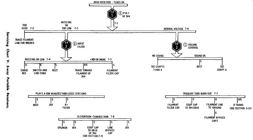
DEAD RECEIVER WITH TUBES OK
The condition of the tubes must be determined first. This is most easily done by making an ohmmeter check of the filaments. Schematics will often contain a warning note that these filaments should not be tested with an ohmmeter, but there is actually no danger in doing so. It is conceivable that some particular ohmmeter might be able to supply more than 1.5 volts at 50 ma on the lowest scale, but it is very unlikely. Besides, there is no need to use the lowest scale. In any case, it is impossible to tell whether the filaments are all lit by looking at them, because they glow very dimly and cannot be seen in a lighted room. Thus, it is obvious that some test of filament continuity must be made.
7-1
Once it has been determined that all the tubes are good, analysis of the circuit begins with TEST POINT 1 in SERVICING CHART V. This is a measurement of the total filament voltage at pin 7 of the 3V4. This voltage may be incorrect in one of two ways-it may be too high or it may be too low, and the corresponding routines are shown separately on the left side of the chart.
If the filament voltage is too high, this can only mean that not enough current is being drawn through the filament drop ping-resistor. This resistor is usually not suspected since it is a wirewound unit and cannot change in value without burning out completely. The technician should suspect a break in the filament wiring between tubes or an open resistor, such as R6, RS, or R9 in Fig. 7-5. A search of the filament circuit with the ohmmeter should reveal the fault.
TEST POINT 2, CHART V FILAMENT VOLTAGE MISSING OR LOW
7-3
If the voltage is too low or completely missing, a different approach is taken. If the filament dropping-resistor is normal, a defect in the power supply should be suspected.
Therefore, the voltmeter is applied across the input filter capacitor, C1 in Fig. 7-5, to measure the power-supply output voltage.
7-4
If this voltage is missing or very low, the surge resistor, switch, line cord, and rectifier should all be checked. The rectifier can be most easily checked by substituting a new one but, when none is available, the ohmmeter can be used by measuring the resistance and then reversing the ohmmeter probes and measuring again. The ratio of forward resistance to the back resistance should be at least 100:1. If the rectifier is found to be defective, the resistance from the output filter to ground should be checked before the new unit is installed, as explained in Section 2 under the heading of Dead Receiver.
In 3-way portables, the normal resistance from B+ to ground is likely to be lower (2K to 3K), because of the low resistance of the filament circuit.
Further Tests When the Voltage at TEST POINT 2 Is Normal
7-5
This excludes the power supply as the cause for the low voltage at pin 7 of the 3V 4 and isolates the faulty part to either the filter resistor R13 (Fig. 7-5) or to the filter capacitor CIC. These can be checked with the ohmmeter or by substitution with new units. Bypass capacitors in the filament line, such as CS and C9 in Fig. 7-2, should not be overlooked as sources of possible trouble.

Fig. 7-5
TEST POINT 3, CHART V FILAMENT VOLTAGE NORMAL AT PIN 7 OF THE 3V4
7-6
When the receiver is dead, and normal filament voltage is found at the beginning of the filament string at TEST POINT 1, this indicates that the symptom is actually a No Signals condition as discussed in Section 3 and 4, with normal filaments and power supply. For this reason, the same procedure of injecting an audio signal at the volume control is recommended to determine whether the RF /IF or audio section has failed. There is one exception in the case of 3-way portables, and this is shown on the right side of the chart under TEST POINT 3. The rectifier should be checked if the injection at the volume control results in sound from the speaker. The rectifier could be weak enough to prevent the oscillator from functioning but still strong enough to provide sufficient B+ to allow the audio sections to work, as explained earlier.
FREQUENT TUBE BURNOUT

Fig. 7-6. Printed-circuit unit used in some 3-way portables.
7-7 This trouble occurs in several ways and is often very difficult to handle because the receiver cannot be left on long enough to make tests. However, a study of any of the filament supplies shown in this section will produce several good suspects. The chart suggests the filament filter capacitor would be suspected, especially when the 3V4 burns out immediately.
The coupling capacitor to the grid of the 3V4 is not such a well-known cause and requires some explanation. In Fig. 7-6, if Cg were shorted, a positive voltage would be applied to the control grid of the 3V 4 with a consequent increase in plate current. The filament circuit is shown redrawn slightly to make clear that plate current in the 3V4 flows through the voltage divider formed by R1 and R2. This current will destroy the 3V4 filament if the coupling capacitor is shorted.

Fig. 7-7. Repairing a defective printed-circuit unit.
In most models, this coupling capacitor is part of a small printed-circuit unit, and the identical replacement may no longer be available. Repairs can be easily made by putting in new components as shown in Fig. 7-7. The terminals leading to the grid of the 3V4, and to grid resistor Rg in the printed circuit unit, are disconnected and new parts installed as shown. The new grid resistor can be safely soldered to pin 1 or 5 of the 3V4 in most circuits, but when this produces distortion because of incorrect cathode bias on the tube, the new grid resistor should be tried on other tube filaments.
Tube filaments can burn out due to a similar defect in an IF transformer which allows B+ to appear on a grid. The method for checking transformers was described in Section 5-11.
DISTORTION AND TUNABLE HUM
7-8
After tubes, the speaker is the most frequent offender in 3-way portables. The 3V4 is often damaged by leakage of its grid coupling capacitor as explained in Section 7-7 and, when ever this tube is the cause of distortion, the capacitor should be changed also.
The mixer-oscillator tube ( 1R5) and the line bypass capacitor are common causes of tunable hum, as in any receiver. The 1 U5 tube has a peculiar characteristic of becoming micro phonic and producing a strange metallic ringing from the speaker. This tube should be replaced whenever there is such a symptom.
-----------------
Oscillation and motorboating are common faults in these portables and usually respond to the procedures described in Section 5. Alignment and tracking are more critical and more important to good performance in these receivers, and the individual instructions for each model should be followed care fully.
QUIZ
1. For what reasons might a customer prefer to have an old 3-way portable repaired, rather than buying a new transistor receiver?
2. In Fig. 7-3, what is the purpose of R12 and C10 in the audio section?
3. In Fig. 7-2, what would be the effect on the sound if R10 were open?
4. In Fig. 7-2, explain the purpose of R9 and what the effect would be if it were open.
5. Show calculations to determine exactly what the grid-to filament voltage is supposed to be on the 3V4 in Fig. 7-2.
6. In Fig. 7-4, assume a total current through R18 of 65 ma, and calculate the value of voltage which would be required at R19. The value will be different from that specified, because of the assumed current in this problem.
7. What are the two most common causes for burnout of the 3V4 filament?
8. A 3-way portable plays about 20 minutes, and then the station disappears, leaving only atmospheric noise. What should you do to repair this receiver?
9. The receiver of Fig. 7-5 is brought in because of distortion, which is corrected by merely replacing the 3V4. Two weeks later the distortion is again present. Explain what should be done to effect permanent repairs.
10. AVC is not applied to all the stages before the detector in the examples shown in this section. Explain the reason why either the IF or the converter stage is not connected to the AVC line.
11. What is the purpose of R7 and R21 in Fig. 7-4?