AMAZON multi-meters discounts AMAZON oscilloscope discounts
Broadly speaking, there are two types of high-voltage probes. One of these, used with DC vtvm's or vom's, is of the resistive type: a multiplier resistor in the probe and the input resistance of the instrument form a voltage divider. The other one, used with an oscilloscope or AC vtvm, is the capacitive type : a small capacitor with a very high voltage rating is used within the probe, while the input capacitance of the instrument and the cable capacitance form another capacitor.
The voltage division which occurs is inversely proportional to these two capacitances. We will discuss the resistive type of high-voltage probe first.
RESISTIVE HIGH-VOLTAGE PROBES
The highest voltage range of most vtvm's and multimeters is usually too low for measuring the very high DC potentials in some sections of television receivers and other electronic equipment.
Direct-current voltage ranges usually are no higher than 1000 volts in vtvm's, and around 1200 to 1300 volts in multimeters.
However, many multimeters have built into them an input series resistor, making possible DC measurements of around 5000 volts.
Nevertheless, the voltage range of these instruments must be extended even further before high-voltage circuits can be measured. Fortunately, this can be done with a high-voltage probe.
A multiplier resistor, built into the insulated handle of the probe, is connected in series with the internal resistance of the meter. The resistor thus acts as one leg of a voltage divider. Its value is determined by the highest voltage to be measured.

Fig. 2-1 . Internal construction of a high-voltage probe.

Fig. 2-2. Simplified DC input circuit of a typical vom.
A typical high-voltage multiplier resistor is about 5/16 inch in diameter and 5.5 inches long, will withstand up to approximately 30,000 volts, and is rated at five watts. Longer or thicker units have somewhat higher ratings . For higher than 30,000 volts, resistors can be connected in series within the probe. The resistors are unusually long to minimize the chance of voltage breakdown between the ends . The resistance itself consists of a high-stability carbon coating applied on a strong moisture-resistant steatite rod. Hence, the detrimental effects of temperature and high humidity on the resistance characteristics are held to a minimum. The coating is wound spirally around the rod. Thus, a very long effective resistor is provided in a small space . This method also permits use of a relatively low specific resistance coating, producing stable resistors with extremely high resistances (up to one million megohms) . The relatively low voltage gradient between turns makes a breakdown unlikely, unless the voltage rating is greatly exceeded. The internal construction of a high voltage probe is shown in Fig. 2-1.
Shielding the multiplier resistor against stray pickup is not practical because this would materially reduce the safety factor gained by using a long resistor and a probe . Permanent connection to the ends of the resistance element or elements is made by means of a silver contact coating. Another coating of special electrical varnish protects the outside of the resistor.
This protective coating must not be punctured because the resistance coating underneath could also be damaged. No solder connections are required between the resistor and external elements, since connection to the resistor is generally made by means of compression springs.
Multiplier resistors are usually chosen to extend the range of a meter by some easily applied multiplying factor-such as 5, 10, 25, 30, or 100.
Let us refer to the input circuit of a typical vom like the one in Fig. 2-2. As we switch from range to range, the input resistance between the positive and the negative terminal varies in direct proportion to the full-scale voltage range at which the meter is set. On the 2.5-volt range, for example, we have 50,000 ohms between the positive and negative terminals (the 48K resistor plus the 2000-ohm meter resistance); on the 10-volt range, we have 200,000 ohms; on the 50 volt range, 1,000,000 ohms; on the 250-volt range, 5 megohms ; and on the 5000-volt range, 100 megohms.

Fig. 2-3. Input circuit of a typical vtvm.
On the other hand, the input resistance of the vtvm in Fig. 2-3 remains constant, no matter where the voltage-range selector switch is set. This input resistance is the five megohms in the isolation probe plus 20 megohms, or 25 megohms, plus the sum of all the voltage divider resistors, which adds up to another 25 megohms. Thus, we have a total input resistance of 50 megohms.
How, if at all, does this difference in the meter input circuit affect the selection of a high-voltage probe? Let us first consider the multi-meter. We said before that the high-voltage multiplier resistor in the probe is part of the voltage divider. In order for it to act as such, we must also know the sensitivity of the meter in ohms per volt (20,000 for the multimeter in Fig. 2-2) . The ohms-per-volt rating of any multimeter is determined by the current required for full-scale deflection. Here, we use a meter with a full-scale sensitivity of 50 microamperes.
By using Ohm's law, we can easily determine the current-limiting resistance required per volt for full-scale reading. Let us say we want to measure 1 volt :
R=? I 1
0.00005 100,000 5
= 20,000 ohms
This 20,000 ohms is the constant resistance required for each volt to be measured. For 5 volts we need 5 X 20,000, or 100,000 ohms ; for 100 volts, 100 x 20,000, or 2 megohms ; for 1000 volts, 20 megohms ; and for 5000 volts, 100 megohms.
To increase the voltage range to 25 ,000 volts full scale by means of a high-voltage probe, we use the 5000-volt range of the meter, and employ the multiplier resistance of the high-voltage probe to drop the other 20,000 volts. Let us figure what resistance we need. Since we must drop 20,000 volts across the multiplier resistor in the probe, and we need a resistance of 20,000 ohms for each volt we want to measure, we simply multiply 20,000 (volts) by 20,000 (ohms/volt) to come up with 400 million ohms (400 megohms).
Setting up a formula for calculating the value of the multiplier resistor for a particular h-v full-scale range is no problem. All we have to know is the resistance at the meter terminals on the voltage range we want to use . Since the multiplier resistor is in series with the meter resistance, the voltage drops will be proportional to the respective resistances . This gives us the following formula:
E .. xt Elnt Rext Rint
or, where, Rillt Eillt Rillt E,'xt
E,'xt is the voltage drop across the multiplier resistor, Eillt is the full-scale voltage reading of the meter,
R,'xt is the resistance of the high-voltage multiplier resistor, Rillt is the resistance between the meter terminals for "Eillt" fullscale voltage readings.
The new full-scale reading is E .. xt + Eillt.
The h-v probe now extends the meter range to 25 ,000 volts.
To read the meter properly, we use the 5000 volt DC scale and multiply the reading by 5. For example, if the meter reads 4000 volts, we are actually measuring 20,000 volts.

Table 2-1. Resistors required for extending the voltage range of non-electronic
voltmeters (20,000 ohms/volt)
A particular value of multiplier resistor is suitable for only one range of the vom. Notice that the internal resistance between the positive and negative terminals of the multimeter in Fig. 2-2 changes with each voltage-range setting. Therefore, a different value of multiplier resistance must be computed for other voltage ranges, using the formula just discussed.
Table 2-1 shows the values of multiplier resistors needed to extend the voltage range of multimeters with sensitivities of 20,000 ohms per volt. Normally it is impractical to extend the high-voltage range of vom's with lower sensitivities, because the power dissipated in the multiplier resistor would be far beyond what could be tolerated. A simple calculation will show what happens when we extend the range of a 20,000 ohms-per-volt vom to 25 ,000 volts, using the 5000-volt range as before-and then if we try to do the same for a vom with a sensitivity of only 1000 ohms per volt.
We previously calculated that we need a 400-megohm resistor for our 20,000 ohms-per-volt vom. From Ohm's law, W
= E2 -7- R, we find the following : (20,000)2 W
= 400,000,000
400,000,000
400,000,000
= 1 watt
At a full-scale reading of 25,000 volts, the multiplier resistor dissipates 1 watt. This value makes it quite practical for us to use the 5-watt, spiral-deposited, high-voltage multiplier resistor available for the purpose.
Now let us see what happens if we try to extend the 5000-volt range of a 1000-ohms-per-volt meter to 25,000 volts . Again using the formula, we find that the multiplier resistor is 20 megohms, and that the power it dissipates for a full-scale reading of 25,000 volts is 20 watts. Such a power value becomes very impractical, of course, not only from a heat dissipation point of view, but also for another important reason . There are few electronic high-voltage circuits from which so much power can be drawn without either causing the circuit to become inoperative, or else to be so loaded down that any readings would be meaningless.
High-voltage probes are used most frequently for measuring the voltages in high-voltage power supplies of television receivers. The voltage regulation of these circuits, however, is inherently poor.
That is, if more current is drawn from the supply than it is designed to deliver, the voltage will drop sharply. Moreover, in such a circuit the loading effect of the probe becomes more pronounced with lower-sensitivity meters. This fact must be considered when voltage measurements are made in television high-voltage circuits . Present-day picture tubes draw a beam current of approximately 75 to 100 microamperes when the set is adjusted for normal brightness. Suppose we use the 20,000-ohms-per-volt meter to measure voltages of, say, 15,000 volts in the high-voltage supply of a television receiver. If we use the probe we designed for a 25,000 volt range, we will apply across this voltage under test a total resistance of 500 megohms. The current drawn by 500 megohms from a 15,000-volt source is:
1= E R 15,000 500,000,000 15 500,000
=
0.00003 amperes, or 30 microamperes.
Television high-voltage power supplies are generally designed to deliver only a limited amount of current at a particular value of high voltage. This current may be very close to the maximum beam current needed when the set is adjusted for maximum brightness. Any further load upon the supply will cause a drop in voltage. An average picture tube, for example, will draw around 300 microamperes of beam current at the maximum brightness setting. If the brightness control is adjusted for maximum and the high-voltage power supply is designed to deliver only 300 microamperes maximum, placing our 20.000 ohms-per-volt meter across the supply would add 30 microamperes, giving a total load of 330. This additional load can cause the high voltage to drop, giving a reading that would seem below normal . On the other hand, had we used a 1000-ohms-per-volt meter and designed a high-voltage probe for it, we would have overloaded the high-voltage supply so much that the resultant reading would have been meaningless. This situation can be remedied by reducing the load on the high-voltage supply when the voltage is measured. If the brightness is reduced from maximum to normal, the required beam current will likewise be reduced (from approximately 300 to 100 microamperes).

Fig. 2-4. Output voltage versus load current of a typical television high-voltage
supply.
Now the additional 30-microampere load placed on the high-voltage supply by the 20,000 ohms-per-volt meter is negligible, allowing an accurate voltage measurement. The load on the high-voltage supply can be even further reduced by disconnecting the high-voltage lead from the picture-tube anode. Fig. 2-4 shows the output capabilities of a typical television high-voltage power supply.
In a properly operating set, the loading effect of a meter can be observed by noting the brightness with and without the probe, and observing any appreciable difference. If the brightness changes, then the loading from the probe varied the output of the high-voltage supply noticeably.
It is possible to use the same h-v probe on several voltage ranges of the vtvm, because the internal resistance of the instrument remains constant on all ranges. When figuring the value of a high-voltage multiplier resistor for a vtvm, however, do not forget that an isolation resistor of anywhere from 1 to 20 megohms is usually placed within the DC probe. (This resistor is removed in changing from the isolation to the high-voltage probe.) Therefore, the DC input resistance of the vtvm (normally in megohms) is reduced by the amount of resistance in the isolation probe.
The value of the multiplier resistor is determined, as before, by the required new full-scale range and the input resistance of the meter.
Here, however, the formula must also take into account the isolation resistor. Thus, we get where, Rp is the value of the high-voltage multiplier resistor, R_in is the input resistance of the vtvm (the value given in the manufacturer's specifications, including the isolation resistor), R_iso is the value of the isolation resistor in the DC probe supplied with the meter, M is the desired multiplying factor for h-v measurements (any easily applied factor, such as 5, 10, 25, 30, or 100). Let us now use this formula to find the proper value of multiplier resistor required to extend the range of the vtvm in Fig. 2-3 to 25 ,000 volts. The 1000-volt scale would give us a multiplying factor of 25.
Thus,
Rin = 50 megohms,
R_iso = 5 megohms,
M=25.
If megohms are used for all resistances, the value of the multiplier resistor will also be in megohms. Therefore, Rp
= R_in (M - 1) + R_iso
= 50 (25 - 1) + 5
= 50 (24) + 5
= 1200 + 5
= 1205 megohms.
If you want to calculate the multiplying factor for a probe with a resistor, the formula becomes Thus, if we had a meter with an input resistance of 11 megohms (with a I-megohm isolation resistor), and a probe with a multiplier resistor of 1090 megohms, the multiplying factor would be
M = 1090 + 11 - 1 11 1100 11= 100.
The multiplying factor of a probe applies to every range of a vtvm because the input resistance always remains constant and no current is drawn from the voltage-divider network to actuate the meter movement.
Table 2-2 shows the values of multiplier resistors required for some of the commercial vtvm's. Many manufacturers produce different models of vtvm's which, as the table shows, sometimes require different probe resistances. The value depends on the total resistance of the multiplier string, so always check to be sure.

Table 2-2. Resistors required for extending the voltage range of vacuum-tube
voltmeters.
We sometimes must use a high-voltage probe with a vtvm to measure in other than very high-voltage circuits. With a high-voltage probe, we can realize extremely high input impedances. That is, the circuit loading by the vtvm will be very low. For example, if we use the vtvm in Fig. 2-3, we will have an input impedance of 50 megohms.
For a measurement on the 100-volt range, we have a sensitivity of 50 megohms divided by 100, or 500,000 ohms per volt-which is quite high. However, we may at some time need a meter with a much higher input impedance, in order to measure, say, 100 volts or so. If our high voltage probe has a 455-megohm multiplier resistor, a multiplying factor of 10 will be introduced in every reading. Therefore, we can now get a full-scale reading of 100 volts on the 10-volt range. Note, however, that the meter now presents to the circuit under test, not 50 megohms as before, but an input resistance of 500 megohms.
This technique of increasing the input impedance of a vtvm will prove very helpful when the voltage in the grid circuit of a television vertical blocking-oscillator circuit is measured. Grid resistors here may range from 10 megohms up and DC voltage levels are below 100 volts.
It is sometimes necessary to measure DC voltage of a few hundred volts in circuits where very large, high-voltage pulses are present (for example, at the plate cap of the horizontal-output tube in a television receiver) . Many service manuals have a note reading "Do not measure" at that point. Here is why: At the plate cap we find both alternating current and direct current.
The DC is the normal B+ voltage of about 350 volts, but the AC component consists of 15,7 50- hz pulses with a peak value of around 6000 volts. Because their frequency is high and their duration short, the meter needle cannot follow these pulses . Hence, they are not read on the meter. They do, however, cause a current to flow in the meter multiplier resistors. As a result, the resistors will overheat, and are likely to open or permanently change in value.
In spite of this problem, we can still measure the DC plate voltage of the horizontal-output tube, provided we use a resistive h-v type of probe. Here, the probe and the input capacitance of the meter (plus the capacitance of the shielded cable, if used) act as a low-pass filter.

Fig. 2-5. Effect on the shunt capacitance of an h-v probe when a doc voltage
containing AC pulses at 15,750 hz is measured. (A) Effective shunt capacitance
for the doc measurement. (B) Equivalent circuit of probe for 15,750- hz pulses.
To explain this, let us use the vtvm input circuit in Fig. 2-3 and the 1205-megohm h-v multiplier probe.
This probe gives us a multiplying factor of 25. We would use the 50-volt range, giving us 1250 volts full scale. However, too much mental calculation would be required. On the other hand, the 10-volt range is too low, giving us a full-scale reading of only 250 volts . We would therefore set our meter to the 100-volt range, since we expect to read in the neighborhood of 300 volts. This gives us a full-scale reading of 2500 volts. Now we can read our B+. But what about the effect of the pulses?
The vtvm has a certain input capacitance-normally around 15 to 25 pf. If the h-v probe uses a shielded cable, it, too, will have a shunt capacitance of anywhere from 50 to 100 pf. Adding these capacitances, we get about 100 pf of total shunt capacitance, as shown in Fig. 2-5A. At 15,750 hz, the reactance of 100 p-f is about 100,000 ohms, or 0.1 megohm. This makes the circuit effectively like that of Fig. 2-5B at this frequency. This 0.1-megohm reactance is in parallel with the total meter input resistance of 45 megohms. However, the effective AC shunt impedance will still be 0. 1 megohm because the effect of the 45 megohms in parallel will be of no consequence.
This impedance, together with the probe multiplier resistor, forms a voltage divider for the high-frequency pulses. The attenuation ratio is therefore 1205 :0. 1, or approximately 12,000 : 1. If the pulses have a peak amplitude of 6000 volts, only 6000 -7- 12,000, or about half a volt, will appear at the meter. This, of course, will not harm it.
Even if the h-v lead is not shielded, we can still use the h-v probe for this measurement. If we take an average vtvm input capacitance of 20 pf, the shunt impedance will be about 0.5 megohm. This will give a pulse attenuation of 1200 : 0.5 , or 2400 : 1. With 6000 -7- 2400, or only 2.5 volts at the meter-still a safe value.
The high-voltage probes are usually terminated by a phone jack, an Amphenol connector, or pin jacks. Since the wire from the probe to the instrument is usually not shielded, only one connection to the meter is required. The common connection from the meter is generally made directly by one of the test leads supplied with the instrument.
CAPACITIVE-DIVIDER HIGH-VOLTAGE PROBES
So far, we have talked about measuring DC high voltages only.
There are times, however, when we will want to measure or observe high-voltage pulses, such as those in the horizontal-sweep system of a television receiver. These high-voltage pulses, you will remember, were purposely bypassed when the resistive high-voltage probe in the previous application was used. They can be measured or observed, however, with a capacitive-divider type of high-voltage probe . Capacitive-divider high-voltage probes are employed with oscilloscopes to check waveforms, and with vtvm's to measure high AC voltages. These probes are not frequency compensated. Their attenuation factor is determined by the ratio of the oscilloscope or vtvm input impedance plus cable capacitance to the high-voltage capacitor in the probe. Since there is no resistive element within the probe, its operation at low frequencies is not too satisfactory. It does, however, operate most efficiently at the higher frequencies found in television horizontal-sweep circuits. The lower-frequency pulses in the vertical sweep section are generally handled more effectively by the 10:1 low-capacitance probe, since the amplitude of these signals is not high enough that a h-v probe is required.
(A) Physical appearance. (B) Basic probe circuit. Courtesy Hewlett-Packard Company

Fig. 2-6. A capacitive-divider high-voltage probe.

Fig. 2-7. Basic capacitive-divider h-v probe circuit, showing how voltage
division is accomplished.
Fig. 2-6A shows a capacitive-divider probe which safely measures as high as 25,000 volts. The frequency range extends from 25 cycles to 20 megacycles. As the frequency increases, the voltage rating of the probe is reduced in order to limit the amount of r-f current flowing through the high-voltage capacitor. A fixed safety gap prevents damage to the probe, should we accidentally apply a voltage higher than the probe is rated for. Breakdown will occur if the applied voltage exceeds about 28,000 volts. Fig. 2-6B shows the basic circuit for this type of capacitive-divider, high-voltage probe.
The probe in Fig. 2-6 is intended primarily for laboratory application, but is included here to show its construction. It has a voltage division ratio of 1000:1. The maximum voltage rating at 60 cycles is 25,000 volts; at 100 kilocycles, 22,000 volts; at 1 megacycle, 20,000 volts ; at 10 megacycles, 15 ,000 volts ; and at 20 megacycles, only 7,000 volts. Fig. 2-6A shows a 15-pf high-voltage vacuum capacitor, which is encased in a glass envelope. One terminal of this capacitor, C1 in Fig. 2-6B, is connected to the high-voltage point and the other to the meter oscilloscope input.
The operation of this type of probe is based on the fact that a voltage applied to capacitors in series will divide between them in inverse proportion to their respective capacitances. If the capacitance of C2 in Fig. 2-7 is 99 times that of C1, 1/100 of the applied voltage will appear across C2 and 9J'ino across C1. This is true because the reactance of C2 is 99 times lower than that of C1. Most of the voltage will appear across the high reactance, of course.

Fig. 2-8. A capacitive divider h-v probe used with a high-impedance probe.
(A) The probe. (B) Probe circuit. Courtesy Boonton Electronics Corp.
As with the resistive high-voltage probe, the element in the probe has the most high-frequency voltage developed across it; only a relatively small amount is developed across the input circuit of the instrument. If we measure 10,000 volts with a 100:1 probe, we find 9900 volts across the high-voltage capacitor of the probe, and only 100 volts across the input circuit of the oscilloscope . The ideal probe would have an infinite resistance and an infinitesimal shunt capacitance. In this way, the probe would not affect the circuit under test at all. (The total capacitance of capacitors in series is less than the smallest capacitance .) In order to realize a very small shunt capacitance, we must make C 1 in Fig. 2-7 as small as possible and still maintain a 99:1 ratio between C1 and the sum of the cable, input, and calibrating capacitances.
Fig. 2-8 shows a capacitive-divider probe for use with a high-impedance probe over a range extending from 500 khz to 600 mc. An exact 100-to-1 division ratio can be obtained by adjusting variable capacitor C1. A very sophisticated solution has been found to the problem of obtaining a low-capacitance and high-voltage "capacitor." This is to use a high-voltage rectifier tube-but as a capacitor, not as a rectifier. These tubes have a very high voltage rating. However, the capacitance between the filament and the plate cap is very small usually around 1 pf.

Fig. 2-9 A shows the details for constructing a capacitive-divider high-voltage
probe. The equivalent circuit is shown in Fig. 2-9B.
The high-voltage input capacitor of this probe consists of the plate-to-filament interelectrode capacitance of a 1X2A high-voltage rectifier tube rated at 18,000 volts maximum. This tube is used as a rather inexpensive high-voltage capacitor with a value of approximately 1 pf. The interelectrode capacitance of the tube is connected in series with the sum of the input capacitance of the oscilloscope, the capacitance of the cable, and the calibrating trimmer capacitor. By proper adjustment of trimmer C2, accurate 100-to-1 attenuation can be obtained.
(b) Equivalent circuit.
Fig. 2-9. Assembling a capacitive-divider h-v probe.
The tube is cemented into the end of a length of polystyrene tubing, and its plate top cap used as the high-voltage test prod. A lead is connected from one of the filament pins to C2 (7-45 pf ceramic trimmer). This capacitor is mounted inside the polystyrene tube. A hole is provided in the wall of the tube so a trimmer-adjusting screwdriver can be inserted.
This trimmer permits the total output capacitance (the sum of the trimmer, cable, and oscilloscope input capacitances) to be adjusted to 99 pf. The voltage-reduction ratio through the probe will then be 100:1 (assuming the interelectrode tube capacitance is 1 pf) . If the tube capacitance is a little more or less than 1 pf, the trimmer can be adjusted to compensate for this accordingly. The calibrating trimmer need not be a h-v type, since only 7100 of the test voltage will be dropped across it. At 15 kilovolts, for example, this will be only 150 volts.
The input impedance of such a probe is approximately 10 megohms, with a plate-to-filament capacitance of 1 pf. At 15,750 hz, the impedance is reduced to about. 1 megohm, which normally is still much higher than the impedance of the circuit under test. If we use the high-voltage probe with an oscilloscope calibrated for a sensitivity of 10 volts peak-to-peak per square, the probe now converts the oscilloscope sensitivity to 1000 volts peak-to-peak per square. Thus, a peak to-peak waveform of 5000 volts will cover five squares.
Most present-day oscilloscopes have a maximum vertical-deflection sensitivity of 0.02 volts rms/inch. This corresponds to 0.02 x 2 x 1.414 = 0.05656 volt peak-to-peak. Thus, to get a I-inch deflection on the scope with a 100: 1 probe, we must have a peak-to-peak input signal of 100 x 0.05656, or 5.656 volts. This is about the practical low-voltage limit for a 100: 1 probe. A 50 : 1 probe is satisfactory where the shunt capacitance of a 10: 1 probe is too high and a 100: 1 probe does not deliver sufficient signal.

Fig. 2-10. A simple capacitive-divider high-voltage probe made from two lengths
of coaxial cable.
A relatively simple high-voltage divider can also be made from two lengths of RG59 IV coaxial cable, as shown in Fig. 2-10. Remove all the outer braid from the shorter coax, and approximately 31;2 inches from the longer one. Then overlap the two pieces of coax three inches, and tape them together with plastic electrical tape. Connect a 100-pf, 500-volt capacitor between the inner and outer conductors of the longer coax in order to obtain the proper attenuation ratio. This capacitance-divider probe gives a stepdown ratio of approximately 100: 1. If you want a more accurate attenuation ratio, use a fixed capacitor of about 80 pf shunted by a small trimmer.
How to Calibrate Capacitive-Divider H-V Probes
Most of today's oscilloscopes are equipped with a decimal step attenuator. By connecting the vertical-input terminals of the oscilloscope directly to a low-impedance pulse source (such as the cathode of the horizontal driver tube, the bottom of the primary winding of the horizontal-output transformer, or the cathode of the damper tube) you can check the calibration factor of the probe . First, turn the coarse attenuator of the oscilloscope to the X100 position, and observe the amount of vertical deflection on the oscilloscope screen. Adjust the vertical attenuator of the scope to any convenient position. Now, connect the 100:1 capacitance voltage-divider probe and advance the coarse attenuator to the X1 position. This will make the oscilloscope 100 times more sensitive . Apply exactly the same signal source as before and do not move the fine attenuator. Adjust the trimmer capacitor to obtain the same amount of vertical deflection as before. The probe is now properly calibrated, and is adjusted to exactly 100:1 attenuation.
After the probe has been calibrated, it is easy to compute the exact value of the peak-to-peak voltage under test, by simply multiplying the oscilloscope calibration factor by 100 (adding two zeros). Such actual measurements can be made only if the probe is used with oscilloscopes that have step attenuators, preferably calibrated in multiples of 10.
The cable supplied with the probe must be kept in use. If another cable is substituted, the probe must be recalibrated.

Fig. 2-11. Connections for checking the waveform and peak-to-peak voltage
in a television high-voltage supply when a capacitive-divider h-v probe is
used.
Uses for the Capacitive-Divider H-V Probe
Some of the less expensive oscilloscopes do not have a compensated input system. The input capacitance of such oscilloscopes will thus vary as the vertical-attenuator setting is varied. Therefore, the calibration factor of the probe at various attenuator settings will also be changed somewhat, and waveform distortion is likely to be encountered at lower settings because of frequency discrimination and phase shift within the attenuator itself. These factors must be considered when this probe is used with an oscilloscope having an uncompensated vertical-input circuit.

Fig. 2-12. Shunting impedance of a typical 100: 1 capacitive divider h-v
probe and a 10:1 low capacitance probe.
The capacitive-divider h-v probe can also be used for measuring the peak-to-peak ripple voltage in the output circuits of a television high voltage supply, provided a suitably rated high-voltage filter capacitor is connected in series with the probe to block the DC voltage component. (See Fig. 2- 11.) Oscilloscopes are generally designed for input voltages up to 600 volts . Distortion will take place if this maximum voltage is exceeded by even a small amount. Moreover, if exceeded greatly, it will damage the oscilloscope input circuit unless a suitable attenuating probe is used. For example, when a 6000-volt peak signal is applied to the 100: 1 capacitive-divider h-v probe, the oscilloscope receives only 1/100 of this voltage, or 60 volts. This is certainly well within the capabilities of the oscilloscope input circuit.
The capacitive-divider h-v probe is suitable not only for quantity, but also for quality measurements. The probe enables the waveshapes of the signal at various test points in the television receiver to be compared with those in the service data.
Because considerable capacitance is shunted across the scope terminals, the resistive components of the scope input impedance can be neglected at high frequencies. Therefore, such a probe does not require compensation at the frequencies encountered in the average horizontal, oscillator-driven television power supplies.
We must realize, however, that since the probe is not frequency compensated, it is not suitable for low-frequency circuits (such as 60 cycle vertical-sweep circuits) because the reactance of the oscilloscope input capacitance at 60 hz would greatly exceed the resistive component of the oscilloscope input impedance. This, however, need not be of concern because the 10: 1 low-capacitance probe will adequately accommodate the operating voltages encountered in vertical-sweep circuits.
The 100: 1 capacitive-divider probe not only loads the circuits less than the 10:1 low-capacitance probe does, but also delivers only one-tenth as much signal. The shunt capacitance is approximately 2 pf for the capacitance-divider probe, and 8 pf for the low-capacitance probe. Fig. 2- 12 shows their shunting effect.
Peak-to-peak voltage readings in television receivers should fall within approximately 20 percent of the reading given in the service manual for the particular set under test. For example, a 5000-volt peak-to-peak signal should measure between 4000 to 6000 volts peak-to-peak in order to be within the normal tolerances expected in commercial television receivers. Remember that the voltage readings in service manuals are generally based on a line voltage of 11 7 volts.
(A) Direct connection. (B) Waveform across coils. (C) Capacitor in series with grounded lead.
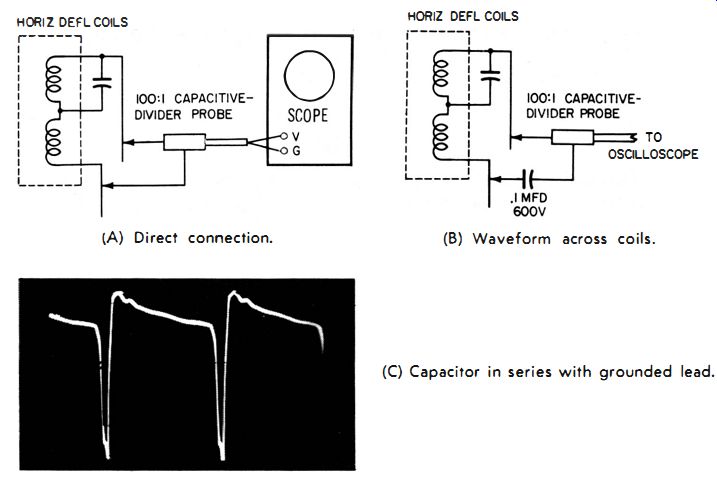
Fig. 2-13. Checking the waveform across the horizontal deflection coils with
a 100:1 capacitive divider probe.
Any variation must be taken into account because it will affect the high voltages in the horizontal-deflection circuits.
Fig. 2-13A shows a 100: 1 capacitance-divider probe applied across the horizontal-deflection coils. The resultant waveform, shown in Fig. 2-1 3C, is almost always indicative of the actual waveform across the horizontal-deflection coils. Sometimes, however, there is sufficient impedance between the "low" side of the deflection coils and ground to produce a distorted waveform. If so, the actual waveform across the coils can be obtained by placing a 0.1-mfd capacitor in series with the ground lead of the probe, as shown in Fig. 2-13B. The capacitance (0.1 mfd here) must be high enough that the AC impedance is negligible. It is not recommended, for safety's sake, that the scope ground be connected to the "low" end of the deflection coil because the scope case will then be at B+ potential, and any contact between it and the receiver chassis will result in a nasty jolt.
SAFETY FIRST
It is interesting to note that sometimes as much as 95 percent of the high voltage under test is dropped within the probe. For example, when 20,000 volts are measured, 19,000 volts may be dropped by the multiplier resistor in the probe, and only 1000 volts within the vtvm. Therefore, the probe must be constructed of a good insulating material, in order to provide maximum protection for its user.
Most present-day high-voltage probes are equipped with a safety flange (sometimes referred to as a flash guard or barrier) consisting of one or more discs about two-thirds of the way up the probe . These discs prevent the operator's fingers from slipping too close to the high voltage source. They also greatly reduce the possibility of corona or arcing.
Some Safety Precautions

Fig. 2-14. A color television interlock "cheater" permits h-v measurements
with the back removed.
The high-voltage power supplies of television receivers can be dangerous. For this reason, television receivers are equipped with an AC interlock that disconnects the power line from the set when the rear cover is removed. It is possible, however, for a charge to remain in the receiver even after the power line has been disconnected. Most color television receivers have a safety device which automatically grounds the high-voltage supply when the back is removed. Fig. 2-14 shows a color television interlock "cheater" that enables the set to be operated even with the back removed. In addition to preventing the high-voltage supply from being disabled, the "cheater" also accommodates a high-voltage probe so voltage measurements can be made.
Be extremely cautious when checking equipment that does not use pulse-operated or r-f power supplies (such as the high current, high-voltage supplies in industrial equipment) . For absolutely safe high voltage measurements, the following sequence is suggested.
1. Turn off the equipment to make sure there will be no high voltage at the measurement point.
2. Connect the high-voltage probe to the meter to be used and set the meter to the required scale.
3. Connect a ground lead between the equipment under test and the meter.
4. Attach the probe to the high-voltage point while the equipment is still turned off.
5. Turn the equipment on and read the meter; then turn the equipment off.
6. Be sure the high voltage has been dissipated before removing the probe.
7. Before checking a transformerless television receiver with an AC powered vtvm, be sure the meter case or negative terminal is at the same potential as the television receiver B-.
The meter ground, if connected to the television receiver, could be the "other side" of the power line. If so, a short circuit will take place. For this reason, it is advisable to use an isolation transformer with the vtvm when this type of receiver is checked.