AMAZON multi-meters discounts AMAZON oscilloscope discounts
A typical home intercom system is a relatively simple electronic gadget in comparison to other items like radio and TV. Any radios that are included in such systems are additional to the actual intercom, which is an ordinary audio amplifier.
The intercom itself only need pass the same range of frequencies as a telephone, about 250 to 2500 Hz. As a result, speakers and transformers are small and inexpensive.
Reliability and quality are easily obtained.
In transistorized units, the amplifiers are usually operated in Class B, which means very little current is drawn from the power supply except when speech is being amplified.
Such intercoms can be left on continuously with little cost per month. There are still many vacuum tube intercoms around, but no new intercoms are being built with tubes. Vacuum tube systems should be shut off at the end of the day, due to heater operating cost and the lowered component life due to heat.
An intercom is a simple audio amplifier and an elaborate switching arrangement. The same amplifier is used to power the base unit and one or more remotes. Switching gets more and more elaborate as remotes are added and becomes extraordinarily complex as other functions are added, such .as radios and paging systems.
The simple intercom with one remote is an audio amplifier, switches and two speakers (Fig. 102). The base station contains the amplifier and one speaker and the remote is simply a speaker. There are switches in both the base station and remote. The speakers are used as both microphone and speaker. When talking, the base speaker is switched into the input of the amplifier. When listening, the speaker is switched into the output of the amplifier .
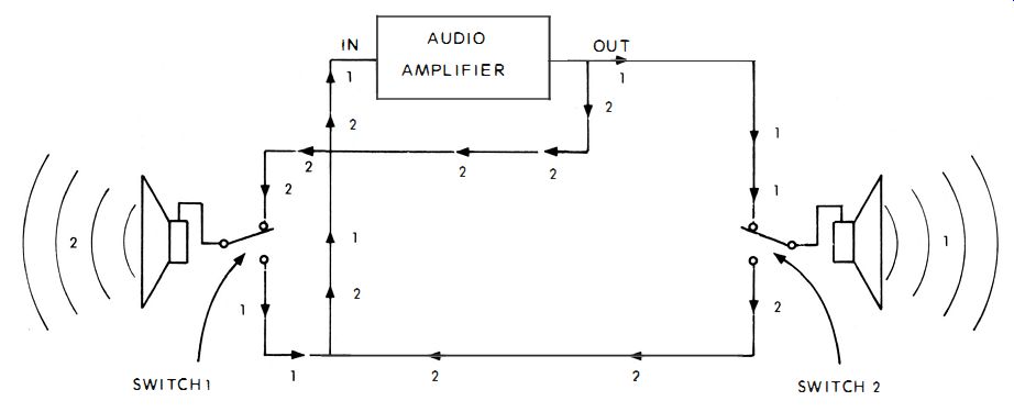
Fig. 102. A simple 2-station intercom is switched as shown in this diagram.
While the base station speaker is being used as a microphone, the remote speaker is switched into the output. Then when the main speaker is being used as a speaker, the remote is switched into the input and is used as a microphone.
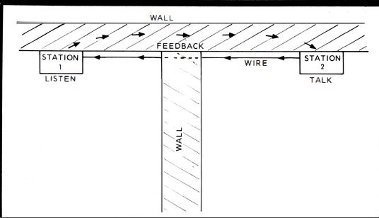
Fig. 103. During intercom installation, stay away from common walls to avoid
unwanted feed back.
No. 166: ACOUSTIC FEEDBACK TEST
Most people interested in electronics are familiar with acoustic feedback. If you are talking on a microphone to an audience in front of you, some of the audio can bounce off the walls re-enter the mike, producing a howl. In intercom systems, a deceptive type of feedback is common.
If every time you talk into the intercom a howl is heard, yet the remote is in another room, where is the feedback coming from? Usually, through the walls (Fig. 103). If you have a common wall between the base station and the remote, your vo ice will come out of the remote and be transmitted through the solid wall, back into the base station microphone. The annoying howl will result. Yet you do not hear the feedback at all. To test whether the howl is really feedback, attach extra wire to the remote and take it into another room. If the howl disappears, then it was acoustic feedback. Try repositioning the remote at different sites in the room you want it in. Also try lower audio volume levels.
No. 167: SIGNAL INJECTION TESTS-SPEAKERS
The typical transistor intercom amplifier produces under a watt of power and can be a simple 4-transistor circuit (Fig. 104) where an audio amplifier supplies, by capacitance coupling, a driver stage. The driver then powers a pair of output transistors in push-pull. When a transistor amplifier goes dead and the power supply is operating, the actual transistor circuit that is causing the problem is easily pinpointed. A 1-kHz note from an audio generator is injected into various test points and the results observed.
When the note is injected into the collector of either output transistor and the 1-kHz tone is heard in one of the speakers (the station or the remote ), it means the speaker is good. Both speakers are cleared by switching them into the output one at a time.
Should one of the speakers not respond to the note as it is switched into the output, it is indicated as defective. If both speakers do not respond, then the audio output transformer is the suspected troublemaker. The note will be at a low volume since there is no amplification at this point.
No. 168: SIGNAL INJECTION TESTS-AMPLIFIER
The amplifier can be quickly examined with the same 1-kHz note. Inject it at the various test points such as the collector and base of the driver and audio amplifier. If you inject the note at the collector of the driver and the note is heard, the pushpull stage is good and the trouble is in the driver or amplifier. No note means the pushpull stage contains the trouble. The note will be heard louder from this test point, since the push-pull stage is able to amplify it.
If you inject the note at the collector of the audio amplifier and it is heard from the speaker, the driver stage is cleared and the amplifier is indicated. No note here means a bad driver stage. Should you get all the way back to the base of the audio amplifier and still hear a clear note, the transistors are all good and the problem is in the input device. No note at the base test point means a defective audio amplifier stage.
No. 169: SIGNAL TRACING TESTS
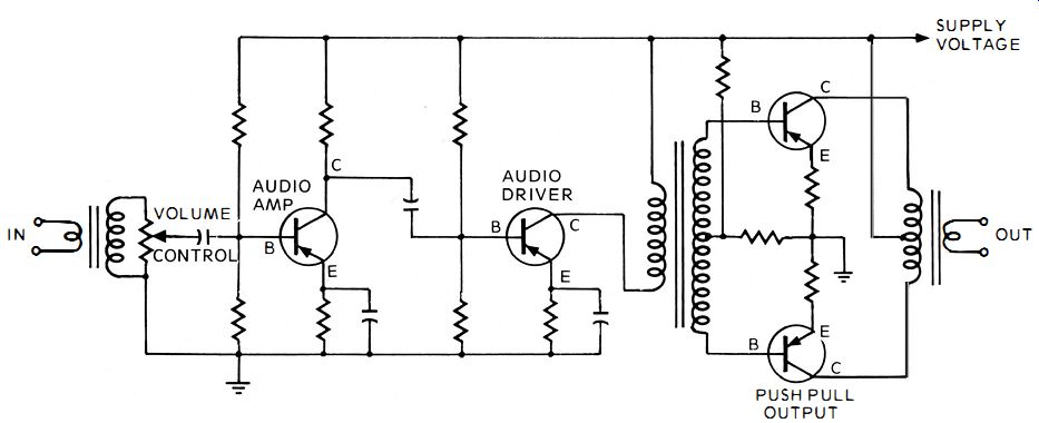
Fig. 104. A typical intercom amplifier is exactly like the audio section of
a radio.
Signal tracing is not as useful a test in intercoms as signal injection. That's because there is no audio passing through the stages during normal operation. You can signal trace, however, if you desire. You can use an audio generator as an audio source and trace the signal with an oscilloscope. The addition of the extra piece of equipment compared to the signal inject ion technique is time consuming. If there is a radio in the intercom, you can use it as a source of audio. Also, you could speak into the system and hold the talk switch down.
Then trace through with the scope. Should you decide to signal trace, the same test points are useful; namely, the transistor bases and collectors. Simply touch the scope to each point and look for an audio display on the scope. As soon as the display is lost, you have passed over the defective circuit.
No. 170: OUTPUT OSCILLATION TEST-TUBE
In the vacuum tube intercom amplifier, a very common problem is oscillation in the output stage. A loud high-pitched whine starts from the unit and continues, becoming a severe annoyance. The oscillation is due to capacitance feedback from the plate to the control grid of the output tube and capacitance feedback of the long lines between stations. A series control grid resistor, typically between 10 and 20K, is placed in the circuit to dampen the oscillation. Even with the resistor, as the output tube ages the feedback increases and the whining occurs. You can test for the amount of resistance you need in series to successfully dampen the oscillation. Unhook one side of the resistor, take a 50K potentiometer and substitute it for the resistor, using the center tap and one end of the potentiometer (Fig. 105). With the pot installed and the amplifier on, vary the resistance. As the potentiometer forms a resistance near zero, the oscillations will begin. Then you rotate the pot the other way, as more resistance is inserted into the control grid, the oscillations will stop as a result of the resistance dampening. However, the more resistance you install in series, the lower the amplifier output will be, because the higher resistance attenuates the signal.
Find a setting on the pot where the oscillations are eliminated and there is still a satisfactory sound level coming from the amplifier. You can either leave the pot in the circuit, or install a fixed resistor of a value corresponding to the setting of the potentiometer.
No. 171: CABLE POWER LOSS TEST-PERCENTAGE
In most inexpensive intercom systems, the output transformer has an impedance of 4 ohms and matches a speaker of 4 ohms. In a radio the amount of wire between the output transformer and the speaker is less than an inch and is, therefore, never considered in design. In an intercom system the amount of wire between the transformer and speaker may be any length. A separation of one hundred feet means in effect that 200 feet of wire is strung between the transformer and speaker, since the wire has two conductors, one each way.
Number 22 wire, the typical type used, has a resistance of 16 ohms per thousand feet. Two hundred feet of wire would have over 3 ohms resistance. This amount of resistance in series with the 4-ohm transformer and the 4-ohm speaker (more accurately about 3.5 ohms) can cause between a 40 and 50 percent loss of the audio. This can be a serious loss in an intercom and has to be considered during the design.
On the other hand, a speaker that has an impedance of 32 ohms and an impedance transformer of 32 ohms will be affected much less. The 3-ohm resistance ,of the wire is a lesser percentage of the 32-ohm units and dissipates just under 10 percent of the audio.
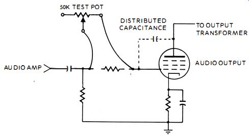
Fig. 105. A tube in an intercom can oscillate. A50K test pot will dampen the
oscillations.
When designing an intercom set up, consider the amount of resistance in the wire. Its percentage in comparison to the total impedance of the speaker and transformer gives you the approximate loss. For instance:
4 ohms of wire 4
4 ohms, spkr + 4 ohms, Xfmr 8 or 4 ohms of wire 4
50%
--- 5 r:1 10 32 ohms, spkr + 32 ohms, Xfmr 64
No. 172: CABLE POWER LOSS TEST
If you have a long run of wire between stations, before actually going through the labor of installing the wire, hook up the units temporarily, running the wire loose between the units. If the number 22 wire is too high in resistance, the volume will not be high enough to be heard satisfactorily. Install larger diameter wire. For instance, try number 18 gauge. Keep lowering the gauge until the audio is loud enough.
No. 173: SPEAKER IMPEDANCE CONSIDERATIONS
In simple intercom systems that employ a master and one remote, common 4-ohm speakers are usually used. Quite often it becomes desirable to add more remotes. The amplifier can easily service the additional units, yet the installer encounters a drastic reduction in volume.
The first thought is that the amplifier can't handle the load. This is usually not true. What has probably happened is that the additional remotes also have 4-ohm speaker and all those 4-ohm units in parallel, plus the additional wiring, causes heavy volume losses.
When such a problem arises, the answer is simple. Remove the 4-ohm speakers and install 32-ohm or 45-ohm speakers. At least use 16-ohm or even 8-ohm types. The additional impedance improves the ratio of speaker impedance to the connection cable loss and also raises the combined parallel impedance of all the speakers to a more normal match with the output transformer.
It works out in actual practice that when the speaker impedances are more than the output transformer impedances, the transfer of energy is more efficient than if the speaker impedances are less than the output transformer. This is because, as the mismatch gets down below 4 ohms, the percentage of mismatch is much higher, than when the mismatch is about 4 ohms.