AMAZON multi-meters discounts AMAZON oscilloscope discounts
Aside from the simple go-no go tests that can be made on a transistor with an ohmmeter or continuity tester , there are other parameters that need testing. Many of the transistor testers on the market today are suitable for such tests. Typical of these is the Sencore TF 151, which performs the tests both in and out of the circuit. It's best to test working transistors in the circuit, unless the transistor is a plug-in type. Removal of a transistor by unsoldering places the transistor in jeopardy while heat and stress is applied. A transistor that is already out of the circuit, of course, is easily tested. It's a good idea to test all transistors before installing them into a circuit.
No. 56 : HANDLING DAMAGE TEST
Transistors are fragile devices , especially the MOSFETs and IGFETs. It's good to know how much damage you have caused to a transistor by simply taking it out of its box and soldering it into a circuit. No matter how careful you are, some damage will occur. Perhaps shortening the leads with a pair of cutters, some static charges from your body or heat from the soldering iron will do it.
The two most important transistor tests are the amount of amplification and the amount of leakage. Make a test before the installation and then again after the device is in the circuit. Notice any differences. Be sure to take any shunt resistances into consideration when reading leakage. The difference between the two readings is the handling damage. If the damage is too great, try installing another transistor. When the damage is slight or almost not recognizable, you have successfully installed the transistor.
No. 57 : CHECKING UNKNOWN TRANSISTOR
Quite often during the repair of electronic circuits, a replacement transistor is needed. In non-critical applications the servicer can quite often get by or confirm a defect by substituting a transistor that bears no physical resemblance to the original. The only two characteristics that must match in these cases are the type and voltage rating. This type of transistor might be available in loose lots of transistors. You can test the transistor quickly and determine its type. You cannot substitute an NPN for a PNP and vice versa, though.
It's a good idea to get yourself set up for this test immediately before the need for the test arrives. If you are set up, the test can be accomplished in seconds. A transistor responds to an ohmmeter exactly as two diodes do-back to back. To check a diode with an ohmmeter , connect the test probes across the diode, take a resistance reading and then reverse the test leads, and take a second reading. A good solid-state diode (we are discussing small germanium and silicon diodes , not the large selenium types) will read a low resistance in one direction and a high resistance when the leads are reversed. The ratio between the two readings should be 10 to 1 or better. The better the ratio , the more efficient the diode.
Actually, what you are doing is injecting a small battery voltage through the diode and a meter (Fig. 58), When the battery's positive side is attached to the anode (or the minus on the diode) and its negative end attached to the cathode (or the plus on the diode) , some of the DC will flow through the diode. This causes a large needle deflection through the meter which denotes a low resistance and, as its called, a forward bias.
To sum up, forward bias shows up on the ohmmeter as a low resistance. The battery, not necessarily the leads of the meter, is attached with the plus of the battery to the minus or anode of the diode. The battery's negative lead is attached to the cathode or plus of the diode. When the ohmmeter leads are reversed, the positive end of the battery is attached to the cathode or plus of the diode and the negative end of the battery is attached to the anode or minus of the diode. The ohmmeter reads a high resistance (very little scale deflection) because practically no DC can flow from the anode to cathode. This is called reverse bias.
Reverse bias shows up on the ohmmeter as a high resistance. The battery is attached with the plus of the battery on the plus or cathode of the diode. The minus of the battery is attached to the minus or anode of the diode. Confusing? You bet, but you must memorize that the plus and minus signs on the diode are opposite to the polarity of the voltage that is attached for forward bias or conduction. Also, you must keep in mind that the positive and negative leads on the meter do not necessarily correspond with the battery polarity. The ohmmeter battery could be attached with the negative terminal to the plus lead and vice versa.
The next thing is that a transistor is thought of as two diodes back to back. Therefore , as you look at the schematic of a transistor and notice the bar and triangle, you see there is only one such set (Fig. 59 ), There are still two diodes in that transistor. The other bar and triangle are not shown. Get into the habit of thinking of a transistor as if the other bar and triangle are actually drawn on the schematic. The second is attached with either the two bars common or the two triangles common.
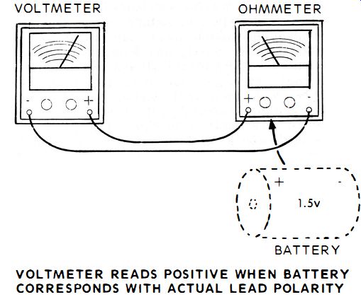
Fig. 58. You can tell battery polarity with your ohmmeter by taking a voltage
reading at the probes.
If the two bars are common, the transistor is a PNP. When the two triangles are common, the transistor is an NPN. Forward bias is a state when current flows from the bar to the triangle. Reverse bias is when DC tries to flow from the triangle to the bar but it can't.
Take a known good PNP and attach your ohmmeter negative lead to the junction between the two diodes or , as it's called, the base. Attach the positive lead first to the end of the top diode and then to the end of the bottom diode. If a low resistance occurs at both ends , you have created forward bias. At a convenient spot, such as on the wall over the service bench, mark a schematic drawing of the PNP transistor with the negative lead going to the junction, the positive lead going to the ends. Then write forward bias , low resistance. That 's it. Whenever you get an unknown transistor, attach your ohmmeter to it in that way. If a low resistance is measured, it's a PNP. Should a high resistance reading be present, it's an NPN, assuming these are good transistors , of course.
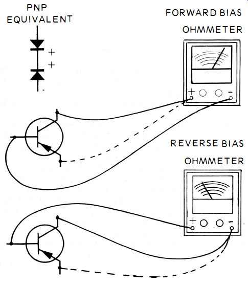
Fig. 59. A go-no go transistor test is quickly made with an ohmmeter considering
a transistor as two diodes.
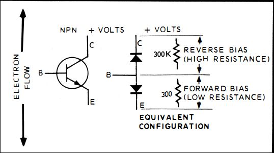
Fig. 60. The bipolar transistor has characteristics similar to two diodes
connected back to back.
No. 58 : DC BETA
With a bipolar transistor (just another name for the ordinary garden variety NPN and PNP types ) beta is the current amplification factor and can be either DC or AC. How does a transistor amplify? Consider the transistor as two diodes back to back. One diode is between the emitter and base, while the other diode is between the collector and base.
Since they are back to back, the forward resistances are also back to back and going opposite directions. In an NPN the forward or low resistance is from E to B and from C to B. That means E to B is a low resistance as B to C is a high resistance.
As a current travels from E to C, it encounters a few hundred ohms between E and B and a few hundred thousand ohms from B to C (Fig. 60). The power gain between B to C becomes many times higher than the power gain between E to B as long as the current remains the same.
The DC beta , or current amplification, compares the amount of E to B current with the amount of E to C current.
The small E to B current causes a large E to C current to flow.
The ratio gives the beta. For instance, if one ma of E to B causes 100 ma of E to C, the beta is 100. No. 59 : AC BETA At low frequencies the AC beta and DC beta are almost the same. Any differences start to occur as the frequency is raised and other factors enter the picture, such as distributed capacitance, resistance and barriers between N and P sections.
AC beta is considered a more valid test than DC, since it is really a dynamic test while the DC is a static one. AC beta is the ratio of collector current change divided by base current change. The collector voltage is held constant during the test.
The AC beta range can double from one frequency to another. Use any readings on a general basis rather than exact when comparing them to a transistor test manual listing. The listing shows a typical mid-frequency range value.
No. 60 : AC BETA TEST SETUP
A bipolar transistor can be tested either in or out of the circuit.
The equipment being tested during an in-circuit test is turned off. Any voltages needed for the test are supplied by the transistor tester. Typically, as in the Sencore TF151, there are three test leads for the bipolar transistor. One for each of E, B and C. In this case red for the collector , yellow for the base and black for the emitter. An NPN-PNP switch places a positive bias voltage on NPN collectors and a negative bias voltage on PNP collectors. A function switch chooses different modes of operation.
Lo-Power, Hi-Power and Special RF.
Most transistors are Lo-Power types. They have less than a watt of output. Any transistors that can provide a watt or more are tested in the Hi-Power position. Critical RF transistors that saturate easily are tested in the Special RF position. Should you test one of these special ones in the Lo Power position, you'll find that under saturation the beta reading becomes less than one. If that happens, try the Special RF position.
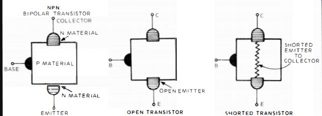
Fig. 61. A transistor breaks down by opening, shorting or leaking. A transistor
tester quickly reveals the condition.
Once the hookup and switches are set, the needle will rise , to a set position. Adjust the Beta CAL knob until the needle is on the Beta CAL line. That calibrates the needle so it will read beta directly. The gain button is pushed and the AC beta is read directly. Multiply the reading by the range switch setting : X1 , X10, or X100. Most readings are made at X10.
No. 61: OPEN TRANSISTOR TEST
When either the emitter, case or collector opens , the transistor will not amplify (Fig. 61 ). It is hard to determine which junction has actually broken since they all act alike. When the transistor is in a circuit , Beta calibration is possible due to all the shunt components that form a resistive network around the suspect transistor. However, when you press the gain button no beta reading occurs. If you should test an open transistor out of a circuit, you can't even get the Beta CAL in place. There is infinite resistance around the broken transistor .
No. 62: E TO C DEAD SHORT TEST
A dead short from the emitter to collector prevents beta calibration. In or out of the circuit, the dead short shunts out all other components and prevents the Beta CAL from registering anything.
No. 63 : E TO C HIGH-RESISTANCE SHORT TEST FOR BETA
When there is a high resistance short from emitter to collector , some beta might be read on the meter , but it will be incorrect. According to the actual resistance of the short, the beta will read near correct for a short in the megohm range to practically no beta in the kilohm range.
No. 64 : E TO C LOW-RESISTANCE SHORT TEST FOR BETA When there is a low-resistance short, under 10K, the meter might calibrate OK. However, when the gain button is pushed, the meter needle will vibrate badly.
No. 65 : B TO C SHORT TEST FOR BETA
Unlike the E to e short where the entire transistor is defective.
since E and e are at either end of the transistor , a B to e short leaves the E to B intact. E to B still demonstrates the front-to back resistance ratio of a diode. With B to e shorted, it 's as if you were testing a diode using a transistor tester with the B to e leads shorted as in a dead short, or with a resistance as in a high resistance short. The tester will calibrate, due to the resistance of the good section of the transistor, but it won't read any gain since the transistor has lost its amplification power. When the gain button is pushed, nothing happens to the needle .
No. 66 : B TO E SHORT TEST FOR BETA
When the base-to-emitter junction shorts, the base to collector junction is still good. The B to e junction acts like a diode with the B to E leads shorted together. The transistor tester will calibrate, but the actual test makes the needle swing all the way to the left or infinity and the needle vibrates.
No. 67 : MAKE-SURE TEST
It is useful to know what your transistor tester does when a particular junction is shorted, open , has a high-resistance or low-resistance short. Even though the transistor tester gives a positive indication of a defect in a specific transistor, you are still not sure if the transistor is being tested in a circuit. You must perform a "make sure test" once you pinpoint a suspect in a circuit, especially if you find that there is another transistor, diode, low-value resistor or capacitor across either the EB or Be junction.
Usually , the make sure test is easy. Life the base connection from the circuit and retest the transistor. If the transistor does not read bad, it is not bad. The reading you received in the circuit was due to one of the shunt components and it probably wasn't defective either. Should the tester still indicate that the transistor is defective, then you are ready for the final make-sure test. Remove the transistor from the circuit and test once more. If it reads defective, it is bad. Be sure to test all the components in shunt with the transistor before installing a new one.
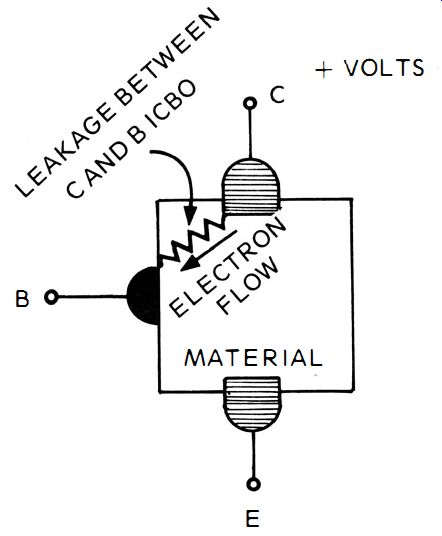
Fig. 62. ICBO leakage is the amount of electron flow that travel s during
reverse bias from C to B. Chances are better than 50-50 that a shunt component
is also defective and has caused the defect in the transistor.
No. 68: TRANSISTOR LEAKAGE TEST
Bipolar transistor leakage is called ICBO (Fig. 62 ). The I is current that is leaking through the collector C to base B. The 0 means there is nothing else in consideration. There is always some tiny leakage between C and B. It is only when it becomes more than is normal that the leakage becomes a defect. In other words, all bipolar transistors have some ICBO, however minute. Unfortunately , an accurate ICBO test cannot be performed in-circuit, unless there is infinite resistance in shunt with the transistor. This means across EB and EC as well as CB. Once out of the circuit the test is simple and almost like an ohmmeter test. The three test leads are attached to E, B and C. The function switch is set to leakage ICBO. The type switch is set on NPN or PNP according to the transistor under test.
This sets up the correct polarity voltage for the leakage test.
The amount of leakage is read directly in microamps.
Considerably more than normal leakage means a poor or hopelessly defective transistor. If there should be less leakage than normal, it usually means an exceptionally good transistor, except if the circuit is designed with a need for the ICBO. Then , less leakage could mean a more normal transistor will have to be used.
Switched Test Leads
Transistors are tiny objects but they can cause all kinds of problems, especially as you test in-circuit and sometimes out of circuit. A common occurrence is getting the test leads interchanged. The multitude of physical configurations compounds the problems. It is useful to know what happens when the leads become interchanged.
No. 69 : SWITCHED LEADS, COLLECTOR AND EMITTER
Quite often when this happens it goes unnoticed and there is no harm done. Many transistors are the actual equivalent of two diodes back to back. When they are, the collector and emitter are almost identical and, in fact, could be attached that way in an actual circuit. Other times, there is a considerable difference between the collector and emitter pieces of N or P material. When there is such a difference, the tester will calibrate fine, but when the gain button is pressed, a very low beta figure is produced. When the beta is ridiculously low, be sure to double check that the collector and emitter leads are not switched.
No. 70: SWITCHED LEADS, COLLECTOR AND BASE
When the collector and base leads are switched, you accidently are placing the collector B plus or B minus voltage on the base. At the same time the base bias voltage is placed on the collector. Without the collector voltage the transistor is almost turned off. The meter will calibrate all right, but the beta will be very low and incorrect. When beta is so low, double check the leads before pronouncing the transistor defective.
No. 71 : SWITCHED LEADS, EMITTER AND BASE
When the emitter and base leads are switched, you have put the emitter voltage on the base and the base bias on the emitter. This reverse bias on the EB junction cuts off the en tire transistor.
If you should begin testing and at the same time switch the type to its opposite polarity, you will have compensated for the switched leads with the type switch. The transistor then is forward biased once more and some E to B current will flow.
However , with the type switch in the wrong polarity position, the wrong polarity voltage is on the collector. No E-to-C current will flow, even with the forward biased E-to-B junction.
With the correct polarity on the type switch, the meter will not calibrate, nor will any gain be shown when the gain button is pressed. With the wrong polarity on the type switch the meter will calibrate, but no gain is shown as the gain button is pressed. When these sets of circumstances occur, be sure to double check the base-to-emitter leads for switching.