(index locations on both: gammaelectronics.xyz and industrial-electronics.com)
An audio booster designed for use in the car from a 12 volt vehicle supply, this device boosts quite musical passages.
THIS AUDIO booster for use with ICE (in-car equipment) provides a genuine output power of 18 watts RMS into 4 ohm impedance loudspeakers from an ordinary 12 volt vehicle supply. It does not require any special transformers, and achieves this output power using an efficient bridge amplifier circuit. The unit is intended for use in negative earth vehicles, and this includes the vast majority of vehicles these days.
A common problem with program sources that have a wide dynamic range is that of quiet passages being lost beneath the engine and road noise. A booster obviously helps by enabling greater volume at all dynamic ranges to be obtained, but the dynamic range of some program sources is too great for this to provide a complete solution.
One way of overcoming the problem, and the one featured in this booster design, is to use signal compression.
This is accomplished by having a level of voltage gain that varies according to the input signal level. At low levels the voltage gain must be higher than normal so that quiet signals are taken above the engine and road noise. At higher volume levels the voltage gain must reduce to a lower level so that overloading of the amplifier and serious distortion are avoided.
The compression is achieved using just a very few extra components, and the unit as a whole is in fact very simple indeed. The compression can be switched out when it is not required. As described here the amplifier is only a monophonic type, but for stereo operation it is merely necessary to make up two amplifier boards.
Operating Principle
Obtaining a fairly high output power from a 12 volt battery supply represents a difficult task. A car battery can supply high currents without risk of damage, but the nominal potential of 12 volts (which is usually about 13 and 14 volts in practice) is rather limiting. An ordinary transformerless output stage gives a peak to peak output voltage that is typically equal to about 9 volts peak to peak using a 12 volt supply. In terms of RMS potential this is little more than 3 volts, and in terms of output power this only represents around 1.3 watts RMS into 8 ohms, or 2.6 watts into 4 ohms. A high efficiency output stage can give a slightly higher output voltage swing of perhaps 11 volts, or even more with a typical battery potential of about 13.5 volts. However, this alone is not enough to give an output power of more than a few watts RMS into ordinary 4 or 8 ohm loudspeakers.
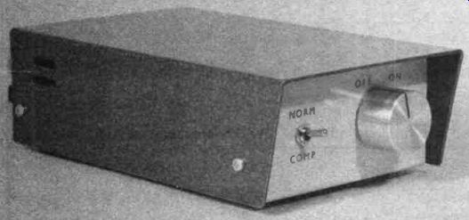
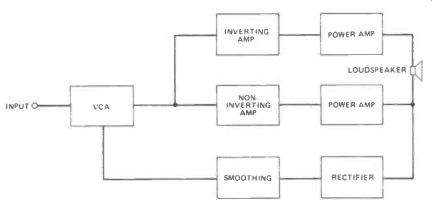
Figure 1. The block diagram.
One method of obtaining higher output power is to use an output transformer to obtain a voltage step-up and a drive voltage that is in excess of the supply potential. There is a neater solution though, and one that is more practical for the home-constructor. This is to use a bridge amplifier, which is really two power amplifiers driving a single loudspeaker. Figure 1 is the block diagram for the Booster/Compressor unit, and this helps to show the way in which a bridge amplifier functions.
For the time being we will ignore the VCA, smoothing, and rectifier stages, which form the compressor circuit and are not part of the booster section. The input signal is applied to two amplifiers which have identical voltage gains, but one inverts the signal whereas the other does not. Each amplifier drives a power amplifier stage, and the two power amplifiers, which are identical, are driven out-of-phase. The loudspeaker is driven from the non-earth outputs of the two amplifiers.
Under quiescent conditions the two amplifiers both have an output potential of half the supply voltage, and the voltage across the loudspeaker is consequently zero. With an input signal applied to the circuit the output voltages will vary up and down, but as the outputs are out-of-phase, as one of them swings more positive the other swings more negative. When one output is driven fully positive the other is fully negative, giving something approaching the supply potential across the loudspeaker. The point that is of importance here is that the polarity of the signal across the loudspeaker depends on which of the outputs is positive and which is negative, and the circuit can drive the loud speaker with virtually the full supply voltage and with either polarity. In other words, the peak to peak voltage drive is nearly equal to twice the supply potential.
Bearing in mind that doubling the drive voltage to the speaker also doubles the drive current, this gives a quadrupling of output power when compared with a conventional amplifier. By using efficient power amplifiers and 4 ohm loudspeakers this enables a typical output power of 18 watts RMS to be obtained from a car battery supply.
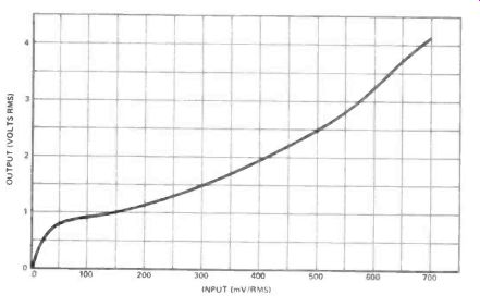
Figure 2. This graph shows the compression characteristic of the prototype
booster.
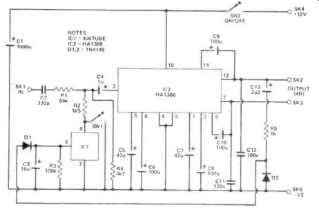
Figure 3. The circuit. IC2 is a special bridge amplifier IC which simplifies
the circuit considerably.
Compressor
The main stage of the compressor circuit is the VCA (voltage controlled amplifier) at the input of the circuit. This has a relatively low attenuation level with zero or small control voltages, but about 10 to 12dB more attenuation with high control voltages. The control voltage is derived from one output of the unit via rectifier and smoothing circuits. This gives a control voltage that is roughly proportional to the output signal level.
At low dynamic levels the control voltage produced is low and the VCA provides its minimum degree of attenuation. As the input signal level is increased the control voltage also increases, producing reduced gain from the VCA and the requires compression effect. 10 to 12dB of compression gives a level of gain which is three to four times higher at low volume levels than it is at high levels. This is not a great deal of compression, but it should give good results in this application. A large amount of compression is not really desirable as it would seriously degrade the effectiveness of many program sources. It is best to use just sufficient compression to ensure that quiet signals are clearly audible, so that the dynamic levels of the signal and its dramatic impact are not seriously impaired.
Figure 2 shows the compression characteristic of the prototype.
Circuit Operation
The complete circuit diagram of the Booster/Compressor appears in Figure 3. The unit is more simple than one might expect due to the use of a special bridge amplifier integrated circuit as the basis of the unit.
The bridge amplifier device is IC2.
This requires several discrete capacitors which mainly provide decoupling for internal circuits or aid stability of the circuit. Two exceptions are C9 and C10 which are bootstrapping capacitors (one for each power amplifier). All these do is to feed some of the output signal of each power amplifier back to its driver stage. This has the effect of raising and lowering the supply voltage to each driver stage in sympathy with the output of the relevant power amplifier. What is of importance in this case is that on the positive output excursions the supply voltage to the driver stage actually becomes greater than the nominal 12 volt supply. This enables a higher peak to drive voltage to be supplied to each output stage, which in turn helps to give a greater peak to peak output voltage swing and output power.
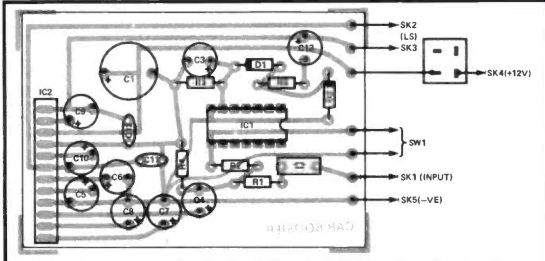
Figure 4. The component overlay. Note that IC2 is an SIL package. Do not push
IC2 all the way down into the board, but leave a length of pin which can be
bent.
The only active element in the compressor circuit is 101 which is a CMOS triple inverter and complementary pair. In this circuit only one transistor in the complementary pair is required, and all the other sections of the device are left unused. The transistor that is utilized is the N channel device, and it acts here as a sort of voltage controlled resistor. The field effect devices in CMOS devices are enhancement mode types which, like an ordinary bipolar transistor, are normally switched off and require a forward bias to bring them into conduction. They are not like the more familiar JFETS which are depletion mode devices which are normally switched on and require a reverse bias in order to cut them off.
An enhancement mode device is ideal for this application. The drain to source resistance forms part of an attenuator.
R1 is the feed resistor while the shunt resistance is formed by a series-parallel network which includes R2 and R4 as well as the MOSFET in IC1. The point of R4 is to ensure that the attenuator provides high losses even when the MOSFET in IC1 is switched off. This is essential since IC2 requires an input signal of only about 10 millivolts RMS to produce maximum output power, whereas the input level to the unit is likely to be more than one hundred times this level. Of course, the volume control on the car radio (or whatever) can be used to attenuate the input level to the booster, but in practice the volume control would be excessively difficult to adjust without the attenuation introduced by R4, and the signal to noise ratio of the system would probably be substantially degraded as well. R2 limits the amount of compression to a satisfactory level. C2 and C4 are DC blocking capacitors.
MOSFETs provide quite good linearity when used as voltage controlled resistors, and in this circuit the low signal level across the MOSFET helps to give low distortion. There is in fact an increase in distortion when the compression comes into effect, but there should be no significant degradation of the audio quality.
The control voltage for IC1 is developed using a straightforward rectifier (D1 /D2) and smoothing circuit (C3/R3). As the input level is increased the control voltage rises, the MOSFET in IC1 gradually becomes switched on, and the losses through the attenuator increase so that the compression is obtained. When SW1 is closed it provides maximum attenuation all the time, and switches off the compression.
Construction
Construction starts with the printed circuit board, details of which are shown in Figure 4.
As IC1 is a CMOS device it requires the usual antistatic handling precautions. Fit it in a (14 pin) DIL IC holder, but do not plug it in place until the rest of the board has been completed.
Until then it should be left in the antistatic packaging, and it should be handled as little as possible when it is fitted into place.
------------------------
Parts list:
RESISTORS:
(All 1/4W 5% carbon) R1 56k R2 1k5 R3 100k R4 4k7 R5 1k
CAPACITORS:
C1 1000uF 16V radial elect C2 330nF carbonate C3 10uF 25V radial elect C4 1uF 63V radial elect C5, 7 47uF 16V radial elect C6, 8, 9, 10 100uF 10V radial elect C11, 12 100nF ceramic C13 2u2 63V radial elect SEMICONDUCTORS 101 4007UBE IC2 HA1388 D1, 2 1N4140
MISCELLANEOUS:
SW1 SPST miniature toggle SW2 Rotary on/off switch SK1 3.5mm jack socket SK2 /3, 4/5 Spring terminals Printed circuit board; case about 150 by 100 by 50 millimeters; control knob; 14 pin DIL IC socket; wire, solder, etc.
-----------------------------
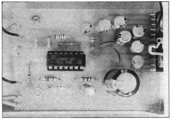
The main point to watch with IC2 is to make sure that it is fitted onto the board the right way round. It has an unusual 12 pin SIL (single in line) package, but pin 1 of the device is still indicated by the usual dimple in the plastic encapsulation. Do not push IC2 right down onto the board in the normal way before soldering it in place, but instead leave a few millimeters of the pins showing on the top side of the board. By bending the pins slightly the heat-tab of IC2 can be brought flush with the edge of the printed circuit board. This is essential and it will not be possible to mount the board in the case properly unless this is done.
Pins are fitted to the board at the points where the seven connections to off-board components will be made.
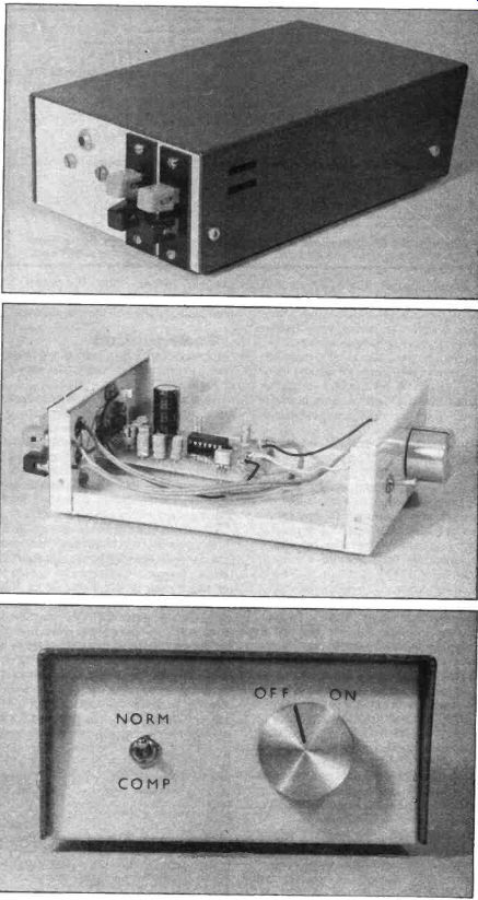
The prototype is housed in a metal instrument case which measures approximately 150 by 100 by 50 milli meters. This is actually somewhat larger than is really necessary for a mono phonic unit, but it could be difficult to make the unit substantially smaller than this as a reasonable amount of panel space is needed to accommodate the controls and sockets. A certain amount of panel space is also required for IC2 which is bolted to the case which then acts as the heatsink. Because the case acts as a heatsink it is essential that it should be of mainly metal construction.
The general layout of the prototype can be seen from the photographs, but any sensible layout can be adopted. The only slight difficulty when fitting every thing into the case is the mounting of the component panel. The main mounting is via the heat-tab of IC2, but additionally one mounting bolt fits through the component panel itself and secures it to the base panel of the case. The holes that match up with the heat-tab of IC2 must be positioned in the case such that the board is about 6 millimeters above the base panel. A spacer about 6 millimeters long is then used on the base panel mounting bolt, between the base panel and the printed circuit board. Note that there is no need to insulate the heat tab of IC2 from the case as both are at earth potential (i.e. the negative supply potential).
If you build a stereo version of the unit a common set of supply input terminals and on /off switch can be used for the two boards. A double pole switch would be needed for SW1, one pole being used in each channel of the unit. SK1 could be changed for a type having two non-earth inputs, or a 3.5mm jack could be used at the input of each channel.
---------------
SHOP:
All the components for this project are straightforward to obtain.
If you have trouble finding the 2u2 63V radial electro capacitor (013) you can substitute one of a higher voltage rating.
The HA1388 (102) is stocked by Watford Electronics (Tel. (0923) 37774) at £ (x 1.4 USD) 2.35.
The cost of the project should come to around £ (x 1.4 USD) 9.50 not including the case of your own choice, and PCB, available from our PCB Service.
-----------
-----------
In Use
The best position for the unit will obviously vary from one vehicle to another, and is something that must be varied to suit your particular circum stances. The unit is not difficult to connect up, but a certain amount of care must be exercised here.
Firstly, when connecting the output of the car radio to the input of the booster be careful to connect the 3.5mm jack plug the right way round, otherwise you will short circuit the non-earth output lead to earth. It is quite in order to leave the existing loudspeaker(s) in circuit and to drive an additional loudspeaker or loudspeakers from the booster. The output from the booster has neither terminal at earth potential, and both outputs must therefore be prevented from coming into contact with the chassis or bodywork of the car. It is advisable to add an in-line fuse in series with the positive supply lead in case a wiring error or fault does occur (a 3 amp fuse is suitable). In order to obtain the 18 watts RMS output power the loud speakers must be 4 ohm impedance types, and you must ensure that they have a sufficiently high power rating.
Also see: SOUND TO LIGHT CONTROLLER -- A bass/complementary light control--as promised last month.