Interested in how a color TV works? Want to know what makes it tick? This special feature by guest writer Don Keithley explains all.
MOST of you will have read the article (if not, why not?!), 'How A TV Receiver Works', in the December 1981 issue of Hobby Electronics, so you will know how a black and white TV works. As you'll soon see, color TV uses all the principles used for black and white TV so you must understand those first.
Briefly, then, you should recall that a black and white TV scene is made up from lots of separate lines (625, in the British TV system) on the face of a phosphor-coated tube. The lines are made by guiding an electron beam from an electron gun across the inside surface of the tube. Controlling voltages applied to the electron gun, and to its deflection coils, tell the beam where to point and how many electrons to send in the beam.
As the electrons hit the phosphor, energy is given off in the form of light and the greater the number of electrons, the brighter the light.
Using these very same principles, we can make a color TV, because the light given off by the phosphor doesn't have to be white (as it is in a black and white TV tube) --it can be red, green, yellow, pink, blue, orange, brown, turquoise, or any color we want it to be. All we re quire is a selection of different colored phosphor spots (say, 10) arranged in groups on the TV screen. All we have to do after that is to fire a beam of electrons at the right colored phosphor spot within each group and hey presto, we have a color TV.
It's Not That Easy
Unfortunately, there are some impossible problems with such a color TV system. For instance:
• If the picture is to be in sharp focus the groups of phosphor spots will have to be very small --in fact, each group must occupy about the same space as the gap between lines on the screen, ie 1/625th of the screen. This means that each spot will be about 1/10th of this size --but this is too small to be accurately manufactured.
• Not only would it be impossible to manufacture such a tube, it would also be impossible to focus the electron beam on to the correct colored spot in each group. Blurring of colors would occur, with greens becoming blues, reds becoming browns, etc. etc.
• Even if the gods were on our side and we were able to produce such a tube, and even if we could focus an electron beam to the required accuracy, there would still be another impossible bridge to cross --can you imagine just how complex the controlling voltages would have to be? The beam would have to be accurately positioned on one exact spot in one exact group of dots; the number of electrons fired in the beam would have to be specified, the beam would have to be fired, then stopped. then moved on to the next group and the whole process started again --for every group on the TV screen. All-in all, the controlling voltages applied to the electron gun and its deflection coils would be so complex that to transmit them over the air would require far more air-space than there is to spare!
• We must also consider the people who won't have color TV, because a black and white TV won't be able to produce a picture from such a color signal (and vice versa) so two completely separate systems would be required, one for black and white and one for color.
As you'll have guessed by now, this color TV system is not the one for us. So what do we do? How do we make a better system? One which is technically possible to build, doesn't use any more valuable air-space, and which we can use alongside the existing black and white system without the two interfering. Let's go back to basics and find out just exactly what 'color' is and perhaps that will give us the answer.
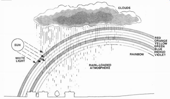
Figure 1. One of the most natural sources of color is a rainbow. White
light from the sun, refracted through a rain-loaded atmosphere, breaks-up
into seven colors.
Mother Nature
Color is a natural phenomenon. You've only to look at the green grass, the blue sky, or the flowering yellow daffodils to see that. Take the example of a rainbow--it's a natural phenomenon, too, but believe it or not a rainbow can be used to show the main principle of color TV. A rainbow is formed when light from the sun (white light, that is) shines through an atmosphere loaded with minute rain particles. Rain particles refract the white light lie bend it) and literally break it up into the seven colors of the rainbow: red; orange; yellow; green; blue; indigo; violet (Figure 1).
The rain-loaded atmosphere acts as a prism, similar to the glass prism used in the simple classroom physics experiment. What that experiment proves is that the color which we call 'white' is simply a combination of other colors.
Theoretically, it should be possible to combine the seven colors of a rainbow, or from a prism, back into white light with another prism.
Figure 2 shows how seven colors can be used to create white light but, given the right conditions, we find that we can get white light from only three colors, red, green and blue. These three colors are called primary colors. The interesting thing is that white light is created by the three primary colors only when they are in the correct proportion: if the proportions differ, then a non white color is created. By controlling the proportion of primary colors, then, a very wide range of non-white colors can be created.
We can show the range of colors obtained with the three primary colors of red, green and blue in what is called a color triangle (Figure 3), where each corner of the triangle corresponds to a pure primary-colored light. Each point inside the triangle represents a different perceived color. White light, at the point of equal primary strengths, is at the centre of the triangle.
You can see from this that we can now make a color TV with a tube which has only three colored phosphor spots--and not the ten colored spots of our first example. Manufacturing such a three-color tube is complex, but not impossible. The colored spots in the tube are arranged in what are called triads lie groups of three), so that each spot has one of a different color next to it. When color TV tubes were first made, these triads consisted of circular spots, as shown in Figure 4a, but later designs have rectangular spots as in Figure 4b.
There are only a few spots shown in Figures 4a and b but, in reality, a color TV tube contains many hundreds of thousands.
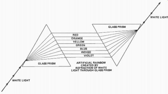
Figure 2. Using a glass prism to create an artificial rainbow from white
light and another prism to recreate the white light from the seven colors
of the rainbow. It would make a good LP cover!
Implications
The use of only three colored spots means that, to get any non-primary color, more than one spot in a group will have to emit light at the same time. To cope with this requirement, more than one electron gun is needed --three, in fact --arranged to fire separate electron beams at each spot in a triad. The electron guns which fire the beams are called red, blue and green guns, not because they fire red, blue and green electrons, but because they are aimed at red, blue and green spots.
Obviously, the red beam in a color TV tube must hit only the red spot of a triad; similarly, the green beam must hit only the green spot and the blue beam --the blue spot. Any cross-over of electron beams, causing the wrong colored spot to emit light, would mean that the wrong color will be emitted and the overall TV scene displayed on the tube will be incorrect: can you imagine blue grass, yellow sky or perhaps pale green people? This is prevented by inserting a metal plate between the tube's screen and the electron guns. In the plate are small holes or slots (one at each triad), which make sure each colored spot is hit only by the beam from the same color gun. The plate is accurately positioned so that each beam is cut-off or 'shadowed' from the other two spots of the triad and thus they can never emit their color when a different beam is fired. Figure 5 shows such a plate (called a shadow mask) and the three electron guns firing beams at the spots of a triad.
Also shown in Figure 5 are the convergence coils which allow the individual electron beam to be adjusted so that, at any one time, they all hit the same triad of spots. If the beams hit spots of the wrong triad, the scene displayed by the tube will have a blurred, out-of-focus appearance, especially in areas of sharply contrasting color changes. By altering the current through the convergence coils, the magnetic fields around them change and hence the deflection of each electron beam can be minutely adjusted until they all hit the same triad. When this is true, the tube is said to be correctly converged.
So --we know how a color TV tube works: the question now is --how do we actually transmit and receive the con trolling voltages which drive the guns in the tube? Remember that our aim is to produce a color TV system which doesn't interfere with the existing black and white system --the two must be compatible! Well, once again we find the answer is to go back to basics, this time to find out just what the actual differences between 'black and white' and 'color' are.
Mono and Chrome
A black and white (monochrome) scene consists only of brightness information, called luminance. We only see the 'greyness' of any particular part of that scene; if part of the scene is very bright we'll see it on the screen as light grey, or perhaps white; if a part is very dark we'll see it as dark grey or perhaps black.
Color scenes possess luminance in formation too --we can always tell how bright a colored object is --but they also have chrominance. Chrominance is the 'magic' ingredient which defines the actual color of an object. It's interesting to note that, although human eyes can detect the two different sorts of visual information, some animals' eyes can't.
Cattle, for example, can't 'see' chrominance information (their eyes simply do not respond to the frequencies which make up 'color'). They can only see in black and white! It's the same thing with TV: a black and white TV transmitter doesn't use chrominance in formation and so the receiver can only display a black and white picture; a color TV system uses both luminance and chrominance information and thus can display the scene in color.
What we have to ensure, though, is that we can transmit both luminance and chrominance without the chrominance information interfering with the luminance. As long as this is so, black and white TV and color TV systems will be compatible and both types of TV receiver will display a picture from the same transmitted signal.
A convenient way of studying a system's waveform (such as that in a black and white TV) is to look at its spectrum. Special machines, known as spectrum analyzers, can be used to find out the size of the signal present at any frequency and display it (much like an oscilloscope displays a simple wave form) on a cathode ray tube. A typical spectrum, which could be obtained from the screen of a spectrum analyzer, of a black and white TV signal is shown in Figure 6. Any other black and white TV signal would be similar. In the spectrum, you can see the band of frequencies which holds the luminance information, corresponding to the number of lines per screen, the position of the electron beam on the screen, and the brightness of the beam at any time. You can also see the narrow peak, at a frequency of + 6 MHz, which is used to send sound information.
The information transmitted for sound is a lot less than that for luminance, hence the sound peak is a lot narrower than the luminance curve.
Darker luminance information, e.g., dark grey and black, is transmitted on the lower end of the luminance curve while lighter information, eg light grey and white, is transmitted on the upper end.
You'll appreciate from the curve that much less 'lighter' information is needed in a black and white TV picture than 'darker' information.
If we were to look at the spectrum of only the chrominance information of a color scene, we would find it much smaller (about 1/5th) than the scene's luminance information. It is this fact which enables us to transmit the two types of information, together, without interference. The possible spectrum of a color TV signal is shown in Figure 7 and the differences between it and the previous spectrum are obvious. The peak holding the chrominance information is at a frequency which, on the previous spectrum, would have been slap bang in the middle of the upper slope of the luminance curve. In the color spectrum you'll see that the upper luminance slope has been taken back a bit so that the chrominance peak doesn't interfere with it. If you remember, the upper end of the luminance curve contains the information of lighter parts of the TV scene, so all we've done in combining luminance and chrominance into one TV signal is to reduce the overall brightness of the received picture --a color TV scene is, therefore, slightly darker than the same scene transmitted in only black and white. To a large extent, a user can compensate for this by turning up the brightness control: so the lack of brightness information isn't regarded as a serious deficit. Hence, a color TV system is compatible with a black and white TV system and the two can run side-by-side without interference.
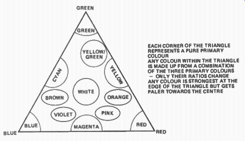
Figure 3. A color triangle. Every color that can be shown on a TV screen can be located in a color triangle.
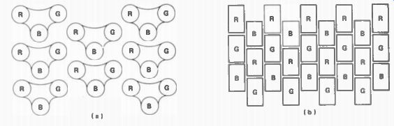
Figure 4. Color triads of phosphor spots; (a) how triads were originally made; (b) the more usual form in use today.
Color Sums
The way in which chrominance is added to the luminance signal to produce the complete color signal is interesting.
There are three gun signals as well as the original luminance signal, so theoretically there should be four separate signals.
However, because of a mathematical relationship between the chrominance and the luminance signals of any color TV scene, the number of signals actually transmitted is reduced to three. If you remember, the three primary colors --red, blue and green --can be added together in the correct proportions to produce white light. Similarly, by keeping the proportions identical but varying the three guns' controlling voltages, grey light can be made. By turning all three guns off, 'black light' is produced too. By keeping the proportions the same, you see, we have in effect made a black and white TV out of a color TV. We can state this mathematically:
xR + yB + zG = L
where: R, B and G are the controlling voltages of the three guns and L is the effective luminance signal voltage which would be applied to a black and white TV gun to produce the same scene; x, y and z are the color proportions required for the condition to exist. Because the pro portions are parts of a whole, then x + y + z must equal 1.
Now, in order that a black and white TV can produce a black and white picture from a color signal, we know that the luminance signal, L, must be transmitted unaltered. But instead of duplicating the information (which we would be doing if we transmitted the three color signals as well) we use a clever bit of maths to reduce the number of color signals: we can send only two color difference signals along with the luminance signal.
The three color difference signals are:
R-L; B-L; G-L.
Now, from the luminance signal already sent in a black and white signal, and two of the color difference signals (say, R --L and B --L), the third color difference signal IG --LI can be calculated. From the above equation we know that: xR + yB + zB = L
And we know that x + y + z = 1, so: xR + yB + zG = (x + y + z)L
Expanding the bracket: xR + yB + zG = xL + yL + zL So: xR - xL + yB -yL + zG --zL = 0
Grouping (you'll see the color difference signals appear now): x(R --L) + yIB --LI + zIG - Ll = 0
So, if we know two color difference signals:
IR -L and B --Ll, the third: G -L = --x IR -LI --y IB – LI
This can all be accomplished electronically by a circuit, known as a color matrix circuit. You can buy them, nowadays, on a single integrated circuit. With the aid of a color matrix IC all the TV has to do is receive the luminance signal along with two color difference signals and the third color difference signal is automatically produced. The TV can then display the complete color picture.
And there you have it; a color TV system can be made using the same principles which a black and white TV system uses --plus just a few more, of course. We've looked at how the transmitted color signal differs from a black and white signal, and from this, we've seen how the two TV systems can run together at the same time, without interference. It's all quite simply really, isn't it?
Roll-on 3D TV!
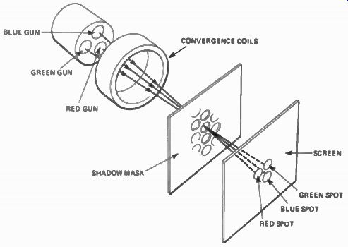
Figure 5. How a shadow mask makes each color-beam strike a spot of its own color; you will appreciate the shadow mask needs to be very accurately positioned. Also shown are convergence coils to position all three beams on to the same triad of spots, at any one time.
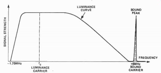
Figure 6. A spectrum of a black and white TV signal showing luminance curve and sound peak.
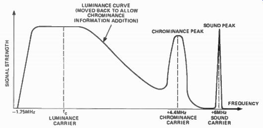
Figure 7. A color TV signal spectrum. The luminance curve is reduced to allow inclusion of the chrominance peak.
-----------------
(adapted from: Hobby Electronics magazine, Apr. 1982)
Also see:
Famous Names--GUGLIELMO MARCONI