| PREV: TYPICAL LOGIC CIRCUITS: Identifying Inputs and Logic in the Circuit | NEXT: |
AMAZON multi-meters discounts AMAZON oscilloscope discounts
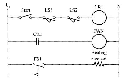
The logic used in ill. 1 (below) is called relay logic because it uses a relay and its contacts to provide logic functions. The term ladder is used because the overall outline of the diagram looks like a wooden ladder. Each line of the circuit looks like a rung of the ladder. Relay ladder logic (RLL) is used quite extensively in industrial electronic circuits. The diagram is drawn to show a sequence of operation. When you are reading simple diagrams, it's usually easier to read them from top to bottom and from left to right. For instance, in the electric heat oven circuit, the first line of the logic shows everything that must be energized before the second and third lines of the circuit can become energized. In more complex diagrams that contain many lines, it becomes harder to read the diagram in strict sequence from top to bottom because a set of contacts from the relay coil in the first line may show up in more than one line of the diagram and these lines may not be consecutive. . AMAZON multi-meters discounts AMAZON oscilloscope discounts |
Another way to read the more complex diagrams is to start with the output you are trying to energize and determine the status of everything in its line of logic. That is, you actually will start from the output point in the diagram and work your way back up the diagram to each occurrence of logic that interacts with this output. For instance, if the logic for a circuit is used to extend an air cylinder, and it's not extending, you could start at the line in the logic circuit where the solenoid coil for the cylinder is. Then test to see if current is passing through all of the sets of contacts to energize it. The set of contacts that's stopping the current flow represents the condition that's responsible for keeping the cylinder from extending.
| Top of Page | PREV: | NEXT: |