| PREV: Programmable Logic Controllers | NEXT: Operation of the Solid-State Logic Circuit |
AMAZON multi-meters discounts AMAZON oscilloscope discounts
|
Earlier in this section we discussed an example of relay logic used to tell a robot which type of taillight was placed on a carrier so the robot could insert mounting studs into it. This same circuit could also be designed to operate using solid-state logic chips. ill. 1 (below) shows the solid-state logic circuit for the taillight detection system. The inputs for this system are proximity switches just as in the relay logic circuit. The outputs are also relays that provide the same signal to the robot as in the previous example. The major difference in the solid-state logic circuit is that inverters are used with AND gates to provide the logic combinations that allow the circuit logic to produce the binary code, which indicates the program request being sent to the robot. The robot program uses the binary code to determine the insertion program that should be executed. AMAZON multi-meters discounts AMAZON oscilloscope discounts |
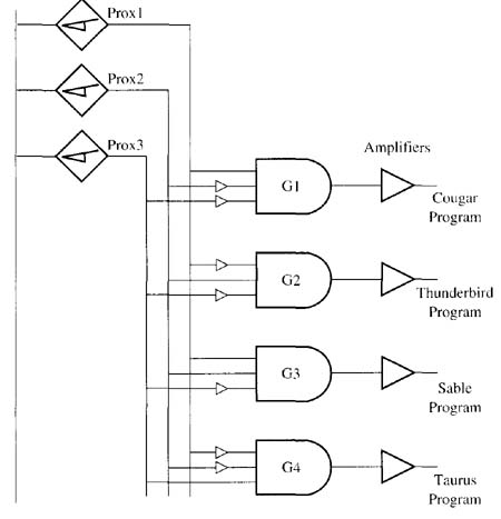
Above: ill. 1: Solid state logic gates
used to provide the logic circuit for the taillight detection system.
The AND gates and inverters are used to provide a binary code signal that's sent to a robot as the proximity switches activate the in puts.
The binary code will indicate to the robot which program should be executed.
| Top of Page | PREV: Programmable Logic Controllers | NEXT: Operation of the Solid-State Logic Circuit |