Clarcia's Circuit Cellar --- Electromagnetic Interference (EMI)
Steve Ciarcia
PO Box 582
Glastonbury CT 06033
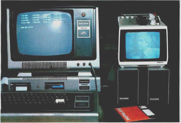
Photo 1a: To illustrate the effects of radiated and coupled interference,
a portable TV set is placed next to an operating TRS-80 Model I computer.
The result is a very snowy picture, primarily the result of radiated
noise. Also note a slight blurring of the characters on the TRS-80 display
screen. A beat frequency caused by magnetic coupling between the two
video displays causes the TRS-80 screen image to shake. In a longer exposure,
the characters would be illegible.
You may have noticed that certain household appliances such as a microwave oven or tools such as a power saw affect television reception when they are running. This television interference, or TVI, is caused by the electromagnetic energy which is radiated when these electrical devices are in use. The general term used to describe such noise is EMI (electromagnetic interference). EMI emanates from both natural and artificial sources. Natural terrestrial EMI sources include lightning discharges, precipitation, and storms.
Man-made EMI can come from electrical-power systems, rotating electrical machinery, gaseous-discharge systems, and electronic equipment such as radar, computers, and television transmitters. Natural EMI is usually beyond man's control, and attempts to reduce it must be centered on the susceptible equipment. Man-made EMI, on the other hand, can be suppressed at the source--this is the most satisfactory way to eliminate interference.
Various forms of EMI are a major concern today due to the rapid growth of digital electronic processing in business, industrial, and home environments. My mail has been overflowing with questions on computer-related interference. The letters have been almost evenly divided between readers who require help in cutting down the EMI emitted from their computers and those concerned with their computers' own susceptibility to noise.
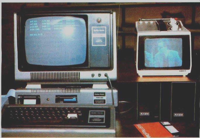
Photo 1b: Demonstration of the effects of shielding. We have added a
line filter to eliminate conductive interference to the setup of photo
la. In addition, two grounded copper sheets, one under the portable TV
set and one to the left of it against the side of the TRS-80 video monitor,
protect the TV set from radiated noise. The results can be seen as greatly
improved picture quality.
The problem has received considerable news coverage lately, due to the FCC's (Federal Communications Commission's) stepping in to regulate noise emissions from personal computers and other electronic equipment. In the past, only equipment intended for certain military applications had to meet EMI limitations.
The few EMI filters that were installed were primarily intended to protect the equipment in which the filters resided from the effects of EMI generated by external sources, entering through the AC (alternating current) power lines.
Little if any thought was given to attenuating electrical noise which was generated within the equipment, leaking out through a variety of coupling paths. Because of the large volume of complaints about EMI that have reached the FCC, the Commission has set new regulations on the maximum level of electrical noise that can be emitted from electronic equipment. These regulations took effect on January 1, 1981. (See "FCC Regulation of Personal- and Home-Computing Devices" by Terry G Mahn, September 1980 BYTE, page 180.) But what about the equipment you own now? What if you have an immediate noise problem? Where do you start to solve the problem? How do you detect where the noise is coming from? How do you break the path between the noise source and the affected receiver? Should you put noise filters on every electrical outlet in the house? How does shielding work? Answering all these questions could easily fill a book. However, because EMI is such a pressing problem for many computer owners, I think it needs to be addressed nonetheless.
This article is intended as an introduction. While not endeavoring to cover all sources and solutions, it will outline the common causes and paths of noise and suggest possible methods for controlling interference. For that reason, I am not limiting the discussion merely to computer-generated EMI and related suppression methods. I hope the result will be a better understanding of the entire problem.
First, a few definitions: Noise: any electrical signal present in a circuit other than the desired signal.
Noise Path: the coupling medium that conducts the noise from the source to the receiver.
Interference: the undesirable effect of noise.
Susceptibility: the capability of a device or circuit to respond to unwanted electrical noise.
Receiver: any circuit or device being affected by interference.
If you own a typical computer purchased before the FCC regulations went into effect, then you no doubt have noticed that it emits considerable EMI. Depending upon the manufacturer and configuration of the system, the extent of the noise may range from a little extra fuzziness in television pictures to an actual blackout of TV reception. The effect upon nearby television sets is dependent upon the level of the emitted noise, the susceptibility of the receiver, and the coupling channel which conducts the noise from the source to the receiver.
Noise Coupling
In order for noise to be a problem, there must be a noise source, a receiver that is susceptible to the noise, and a coupling channel that transmits the noise to the receiver. The relationship is shown in figure la.
We start to analyze a noise problem by defining what the noise source is, what the receiver is, and how the source and receiver are coupled together. It follows that there are three ways to break the path:
1. The noise can be suppressed at the source.
2. The receiver can be made insensitive to the noise.
3. The amount of energy leaking through the coupling channel can be minimized.
There are three forms of noise coupling: conductive, common-impedance, and radiated-field coupling. Figure lb demonstrates a typical situation. In this circuit, the commutator noise generated from the motor is both conducted along and radiated from the leads going to the motor-control circuit. Also, the motor control and the television receiving set are plugged into the same long extension cord, so they share a common line impedance. The coupling channel consists of: conduction on the motor power-supply leads radiation from the leads common line impedance To eliminate the motor's influence on the TV, all three parts of the coupling path must be broken. You can apply EMI controls to any or all of these elements.
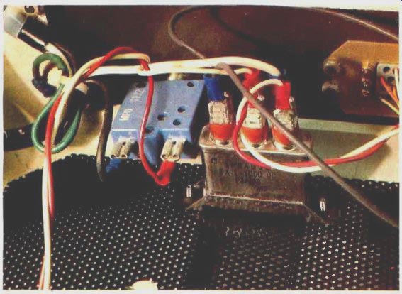
Photo 2: The simplest method of noise reduction is to use capacitors
as simple filters. This photo shows two 0.1 µF, 1000 V capacitors used
to filter the AC power line in a video terminal.
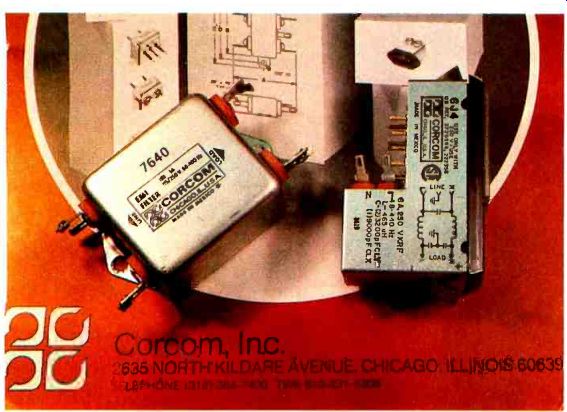
Photo 3: Commercial power-line filters from Corcom Inc, 2635 North Kildare
Ave, Chicago IL 60639. Prices range from $10 to $20.

Figure 1a: The general case of the transmission of electrical noise.
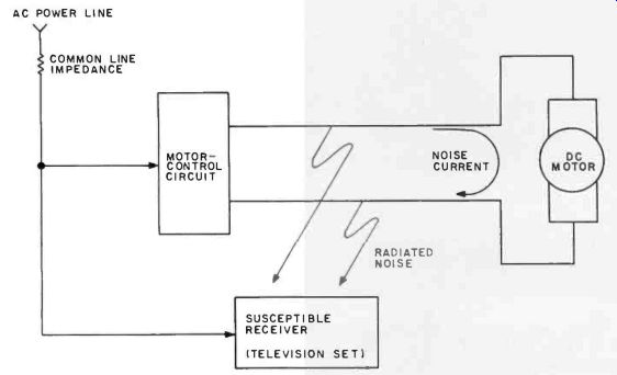
Figure 1b: A typical noise-coupling situation: commutator noise generated
by the motor is conducted along and radiated from the connecting leads.
Common line impedance shared by the receiver (a television set) and the
motor cause motor noise to be imposed on the receiver's power input.
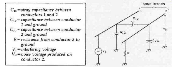
Figure 2: Representation of capacitive coupling between two conductors.
The definitions of the symbols are listed above.
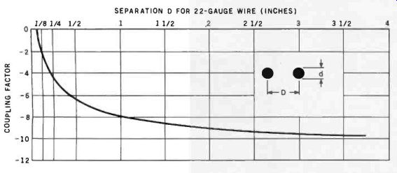
Figure 3: The relative effect of capacitive coupling of noise is dependent
upon the distance between conductors. In the chart shown, for22-gauge
wire, coupling is significant only when the conductors are closer together
than 25 mm (1 inch).
Conductive Coupling
Conductively coupled noise is often overlooked. A wire passing through a noisy environment picks up noise either by capacitive or magnetic coupling and conducts it to another circuit. A simple representation of capacitive coupling between two conductors is shown in figure 2.
When the resistance from conductor 2 to ground, R, is large, the voltage coupled from conductor 1 to conductor 2 is defined as follows:
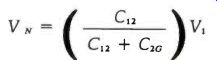
where C12 is the stray capacitance between conductors 1 and 2, C1G is the capacitance between conductor 1 and ground, C2G is the capacitance between conductor 2 and ground, R is the resistance from conductor 2 to ground, V, is the interfering voltage, and VN is the noise voltage produced on conductor 2.
Even though this may appear small (perhaps a few microvolts), remember that some receivers amplify input signals thousands of times. A few microvolts of noise on the antenna terminals of a television set could easily be greater than the desired video signal.
Figure 3 shows the effect of conductor spacing on capacitive coupling.
The coupling factor is said to be 0 dB (decibels) when the two conductors are separated by a distance equal to three times the conductor diameter (for 22-gauge wire, d =0.71 mm or about 0.028 inches); the factor decreases rapidly as the spacing increases. Separating wires reduces the capacitive coupling between them. However, little is gained by spacing the conductors more than 40 diameters apart (about 25 mm or 1 inch).
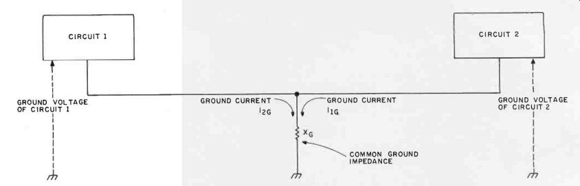
Figure 4: Common-ground-impedance coupling is caused by two pieces of
equipment using the same electrical lead to ground. The ground current
of one influences the ground-reference voltage of the other, and vice
versa. One solution to this is a single-point grounding system.
Figure 5: Common-power-source coupling occurs within a computer that uses a single power supply for multiple peripheral devices. Due to the impedances on the connecting lines, the current drawn by one circuit changes the voltage "seen" by another circuit.
Magnetic Coupling
Magnetic coupling is also a problem. When a current flows in a closed circuit, it produces a magnetic flux which is proportional to the current.
If two wires are parallel, the flux produced in one wire will induce a voltage in the second wire. This induced voltage constitutes noise.
When you are running wires between sensitive electronic components, avoid laying signal wires parallel to noisy, high-current AC power lines. If a signal line must cross a power line, have it do so at a right angle.
Common-Impedance Coupling
Common-impedance coupling occurs when currents from two different circuits flow through a common impedance. Two examples of this type of coupling are shown in figures 4 and 5. In figure 4, the ground currents of both circuits flow through a common ground impedance. The ground potential of circuit 1 is modulated by circuit 2, and vice versa. Any fluctuations in the ground current of circuit 2 will be coupled through the ground impedance, XG, to circuit 1.
Another example is the power-distribution schematic diagram shown in figure 5. Any change in the current required by circuit 2 will affect the voltage at the terminals of circuit 1. This effect is due to the common impedance of the power-supply lines and internal source impedance, Rs, of the power supply. Shorter leads will help reduce the line impedance, but the source impedance always remains. The typical computer system plagued with common-impedance noise is one where the builder has attempted to use the processor power supply to run everything, including peripherals.
The apparent economy is outweighed by periodic system crashes and unpredictable errors.
Radiated-Field Coupling
Radiated electric and magnetic fields provide the last form of coupling. This form of coupling can be most easily thought of as free-air radio transmission. The interfering circuit broadcasts noise just like a radio station, and every conductive surface in the receiver acts as an antenna. At close distances, the noise can in fact be much stronger than a real radio station. [Many readers probably know of methods for generating computer music by using an AM radio to pick up computer-emitted noise while the appropriate program runs...RSS] The characteristics of a field are determined by the source of the field and the distance between the source and the point of observation. When the receiver is near-field, closer than 1/6 wavelength, the electric and magnetic fields are considered separately. Any source /receiver distance greater than 1/6 wavelength is far-field, and the electric and magnetic fields are considered together and are called simply the electromagnetic field.
At frequencies below 1 MHz, most coupling is near-field, because the near-field boundary at the corresponding wavelengths extends out to approximately 45 meters (150 feet) or more. At 100 MHz, most coupling is far-field. For purposes of this discussion, however, radiated-field-interference problems within any given piece of equipment should be considered to be caused by near-field radiation unless the interference is clearly from far-field radiation.
Finding and Fixing a Noise Problem
The key to solving a noise problem is finding the source of the noise. In fact, your computer might not be the culprit. More than one computer owner has suffered complaints about his "computerized noise generator" only to later find that the real source of the interference was the solid-state light dimmer on the overhead light.
Continuous sources of noise are easier to identify than intermittent ones. The interference from appliances and computers is usually broadband, affecting the entire radio-frequency spectrum. Digital waveforms are especially rich in harmonic frequencies, as shown in figure 6. Therefore, the continuous, harmonic-rich emissions of computers are relatively easy to find.
A standard battery-operated AM radio makes a good EMI detector. With it tuned to a frequency at which the noise is the loudest, just roam around the house looking for the place where the interference is the strongest.
If you suspect the computer, then move the radio around it and along the connecting cables. You will be surprised how much the cables contribute to radiated noise. Disconnect cables and peripheral devices selectively to further isolate interference sources. Often, the long leads between the computer and printer emit electromagnetic radiation as well as any transmitting antenna you could have possibly designed.
Finally, move the radio along the power cord you have supplying the computer system. If you are using a 15-meter (50-foot) extension cord without the ground lead connected, shortening the cord will reduce radiation considerably.
If the computer system is indeed found to be the source of the interference, there are a variety of possible coupling paths. The coupling efficiency of digital interference is proportional to frequency; the higher the frequency, the greater the interference. Depending upon the design, these interfering signals can radiate from the source, couple from line to line, or be conducted directly through connecting wires to the external environment. Each noise path must be suppressed.
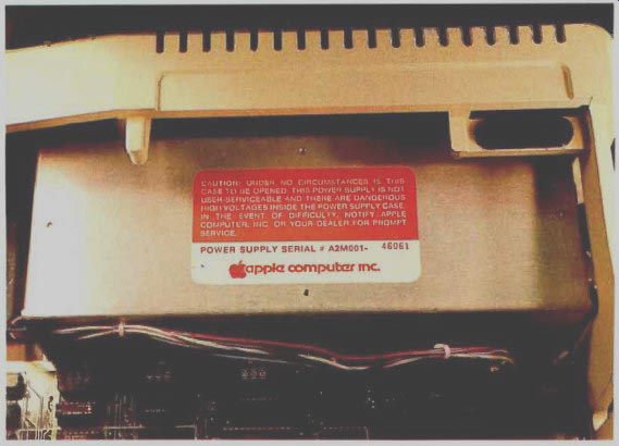
Photo 4: Switching-type power supplies, which use high-frequency pulse-width-modulated
waveforms, are a potential source of noise. Most often they are contained
in shielded enclosures, as in the Apple II, to eliminate possibly interfering
radiation.
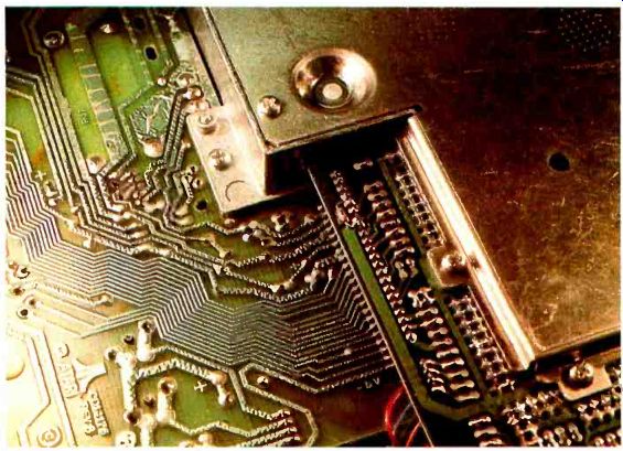
Photo 5: The Atari 400 and Atari 800 personal computers are designed
to eliminate any forms of EMI coupling and to meet the new FCC standards.
This requires considerable shielding. The high-frequency processor and
memory sections of the printed-circuit board are segregated from the
power supply and I/O (input /output) areas. A heavy-gauge aluminum enclosure
encircles the high-frequency sections, as shown in this Atari 800.
Grounding
Grounding is the primary way to minimize unwanted noise and pickup. It is often the optimal solution to most problems. There are two basic objectives in designing proper grounding systems. The first is to minimize the noise voltage generated by currents from two or more circuits flowing through a common ground impedance; the second is to avoid creating ground loops which are susceptible to magnetic fields and differences in ground potential. This ground is the reference point for all voltages in the system.
Signal grounds are generally classified as either single-point or multipoint grounds. From a noise-reduction point of view, the single-point ground is more desirable. Normally, with equipment operating at frequencies below 1 MHz, a single-point system is used. Above 10 MHz, a multipoint ground is best, to minimize ground impedance. Between these bounds, the type of grounding depends on the system configuration and layout. For personal computers, single-point grounding is advised.
The AC power ground is of little practical value as a signal ground. It is usually connected to signal ground as a safety measure only.
Shielding When properly used, shielding is an effective means of reducing the coupling of noise between conductors. Shields consist of a variety of conductive materials (usually steel, copper, or aluminum), all of which serve in some way to reflect, absorb, or otherwise channel noise currents away from the protected conductor.
Shields may be placed around components, circuits, complete assemblies, cables, or transmission lines.
A parallel-tuned trap cannot be used for broadband computer-generated noise.
The best way to minimize radiated noise and susceptibility on connecting wires is to use coaxial cable (coax) or shielded twisted-pair cabling between peripheral devices and the processor.
If the coaxial-cable shield is grounded at one end, it will protect the central conductor from electric-field radiation. Grounding the shield at both ends creates a return current in the shield, which generates a field that cancels the conductor's electric field and any magnetic interference as well.
In twisted-pair shielded wire, grounding the shield at one end takes care of electric fields, while twisting the conductor with the return line serves to reduce magnetic susceptibility. (Twisted-pair shielded wire is especially useful on low-level signals.) The number of twists per foot determines the insensitivity to magnetic fields.
When comparing coaxial cable and shielded twisted-pair cable, it is important to recognize their differences in signal propagation, irrespective of their shielding characteristics. Shielded twisted-pair cable is very useful at frequencies below 100 kHz. Above 1 MHz the signal losses are considerable.
Coaxial cable, grounded at one end, provides a good degree of protection from capacitive pickup and can be used at all frequencies from DC (direct current) to UHF (ultra-high frequencies). However, due to the potential for noise currents to flow through the shield (which is also part of the signal path), coaxial cable is better used at higher frequencies where such errors are minimized.
Shielded twisted-pair cable, on the other hand, does not exhibit this problem and should be used for conducting low-frequency signals.
An unshielded twisted pair, unless it is balanced, provides very little protection from capacitive pickup, but can still be good for magnetic-field protection. Plain untwisted-pair cable, such as the zip cord you might purchase from a hardware store, provides no electromagnetic-field protection and should be avoided if you have a noise problem.
Multiple-conductor cables, including ribbon cables, are also available in twisted-pair configurations. A common cable used in data acquisition is a twelve-conductor shielded cable that consists of six twisted pairs surrounded by a single foil or braided shield. This cable is very expensive, however, and it is best acquired on the surplus market.
Shielding the connecting cables may eliminate only part of the problem, especially if you determine that the major source of radiation is the computer. Most computers are encased in metal chassis. If these are not properly grounded, the benefits of the metal as shielding material are lost.
On the other hand, if the computer is encased in plastic, the only solution is to coat the inside (or the outside) of the case with a conductive substance and connect it to signal ground.
Aluminum foil, for example, could be used, but I suggest that you try all the other suppression measures before attempting this.
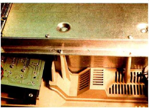
Photo 6: The underside of an Atari 800. Metal plates enclose the processor
and memory. The green printed-circuit board on the lower left contains
the keyboard circuit. Since it runs at low frequencies, it does not require
a shielded enclosure.
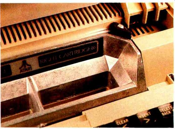
Photo 7: The Atari computers allow the user to plug in special game
and business program cartridges. These ROM packs (read-only-memory modules),
which are connected directly to the processor bus, must also be kept
within the shield when the computer is running. This is accomplished
using a special molded, 3/8-inch (9.5 mm)-thick socket that is electrically
part of the shield. A plate of aluminum with conductive gasket material
around the edges is attached to the cover. When the cover is closed,
the memory is completely shielded and virtually no electrical noise is
emitted.
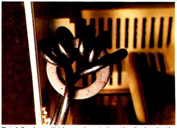
Photo 8: To reduce any high-frequency harmonics that might radiate from
the video-monitor cable, a toroidal ferrite core may be wrapped in the
line.
========
Summary of Noise-Reduction Techniques
Suppressing noise at the source:
1. Enclose noisy sources in a shielded enclosure.
2. Filter all leads leaving a noisy environment.
3. Shield and twist noisy leads.
4. Ground both ends of coaxial-cable shields to suppress radiated interference.
5. Limit pulse-rise times where possible.
Eliminating noise coupling:
1. Twist and shield signal leads.
2. Ground shielded leads used to protect low-level signals at one end only.
3. Avoid ground leads in common between high-level and low-level equipment.
4. Keep ground leads as short as possible.
5. Separate noisy and quiet leads.
6. Use a single-point grounding system.
7. Avoid ground loops.
8. Keep sensitive-signal leads as short as possible.
Reducing noise at the receiver:
1. Use frequency-selective filters where applicable.
2. Use shielded enclosures for sensitive circuitry.
3. Provide proper power-supply filtering.
4. Separate signal and hardware grounds.
5. Use shielded cables to protect low-level signals.
=========
Encasing the entire computer in a conductive enclosure is not unthinkable. In fact, newer small computers such as the Atari 800 and Hewlett-Packard HP-85 are built exactly that way. It is very effective in both containing the computer's electromagnetic fields and protecting the computer circuitry from external noise. When an EMI field impinges on a shield, some of its energy is reflected at the first surface, some is absorbed by the shield material, some is reflected by the second surface, and some passes through. In general the following is true of enclosure-type shielding: Magnetic fields are harder to shield against than electric fields. Magnetic material should be used to shield against low-frequency magnetic fields.
At high frequencies, a good conductor suitably shields against both electric and magnetic fields.
Shielding effectiveness is increased with thicker shielding material.
In practice, actual shielding effectiveness obtained is determined by the leakage through seams and joints, not by the shielding effectiveness of the material.
Filtering Grounding and shielding were prescribed to eliminate noise at the source. The final measure, filtering, is applicable either at the source or at the receiver. Filtering is generally the easiest form of noise abatement. It is primarily used to reduce noise conduction into or out of the AC power lines.
A circuit used as a power-line filter is a low-pass filter ideally designed to suppress all frequencies above 60 Hz.
Such filters are commercially available from many sources but are also easy to construct.
If you prefer to build a simple line filter, figure 7 shows the schematic diagram of a typical circuit. This circuit is applicable for use in instances of minor television interference. It should clear up most line-coupled noise problems.
As a practical matter, simple line filters are less than ideal. Typical commercial single-section line filters use toroidal inductors and provide about 55 dB of attenuation at 3 to 5 MHz. Attenuation can be typically increased to 70 dB by adding a second LC (inductance /capacitance) section.
A line filter should be used on the computer and any susceptible receivers.
If your TV reception is still garbled or nonexistent after you install a line filter, then your set is picking up radiated noise through the antenna input. Generally, you will find the VHF (very-high-frequency) channels to be affected much more than the UHF channels. This is because most of the noise energy generated by the computer is at frequencies below 100 MHz (VHF channels 2 thru 6 are between 54 and 88 MHz). At frequencies above 470 MHz, where channel 14 starts, there isn't much energy in the noise spectrum.
The process of eliminating radiated-noise pickup starts with replacing the 300-ohm twin-lead cable from the antenna to the television receiver with 75-ohm coaxial cable. If the problem persists after you do this, then additional filtering is in order. If the noise is determined to be a single frequency, such as that emitted from a Citizens' Band radio transmitter next door, then a parallel-tuned trap that singles out this one frequency should be used. Figure 8 shows such a filter circuit.
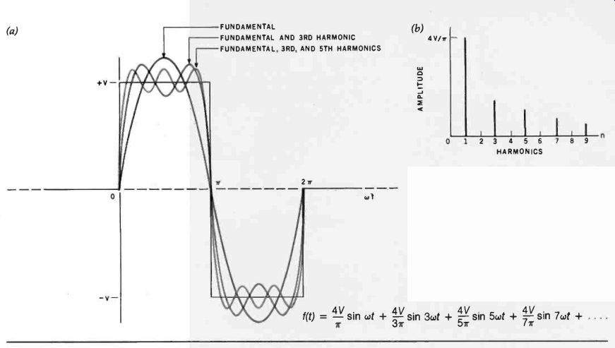
Figure 6: Within the computer and between peripherals, signals are digital.
(6a)
Such signals are square waves with very fast rise times, composed of the fundamental frequency, w, and all the odd harmonics of the fundamental frequency.
In a computer with a clock frequency of 8 MHz, there will be radiated noise at 8 MHz, 24 MHz, 40 MHz, etc. (6b) The amplitude becomes less at each higher harmonic.
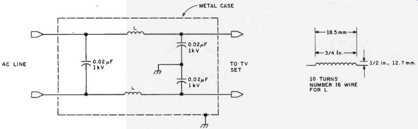
Figure 7: A simple low-pass line filter with homemade inductors.
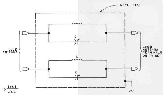
Figure 8: A parallel-tuned trap filter for use on FM-radio or television
sets. Each LC combination is set for resonance at the frequency that
is causing the interference. Trap filters are suitable only for eliminating
narrow-band interference such as that from Citizens' Band radio transmitters.
Here, the center frequency trapped by the filter can be calculated from the equation fo= 159.2/ LC , where fo is the resonant frequency in Hertz, L is the inductance in microhenrys, and C is the capacitance in microfarads.
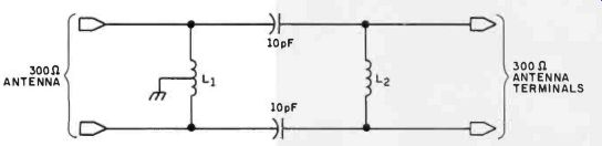
Figure 9a: A high-pass filter for use with 300-ohm antenna cable. A
high-pass filter can be used on television-receiving sets and FM-radio
receivers to reduce or eliminate noise at frequencies under 50 MHz, such
as that produced by personal computers. These filters pass frequencies
above 54 MHz (where the VHF-TV broadcast band lies) and attenuate any
lower frequencies where noise may reside.
In this design, the inductors L1 and L2 are made from eight turns of 18-gauge wire in a coil 19 mm in diameter, 25.4 mm (1 inch) long.
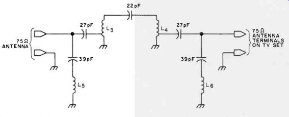
Figure 9b: A high-pass filter for use with 75-ohm coaxial antenna cable.
In this design, inductors L, and L, are made from four turns of 14-gauge
wire in a coil 6.35 mm in diameter and 12.7 mm (1/2 inch) long, tapped
one-half turn from the end. Inductors L, and L6 are made from ten turns
of 22-gauge wire in a coil 6.35 mm in diameter, with the turns spaced
at 3.175 per cm (8 per inch).
Computer-generated noise is broadband rather than narrow-band.
A parallel-tuned trap cannot be used, and a different filtering technique must be employed. A high-pass filter on the set's antenna input may be needed. The system clock frequency of most computers is between 1 MHz and 8 MHz. Harmonics will, of course, reach much higher frequencies. The harmonic amplitude diminishes with each successive frequency multiplication.
If we can presume that practically all of the radiated noise is below 54 MHz where channel 2 starts, then we can construct a filter that passes only the frequencies above 54 MHz. The filter should actually be set for a cutoff frequency of 45 MHz to reduce attenuation at the desired frequencies above 54 MHz. In combination with coaxial cable, the high-pass filter usually remedies 80% of all interference problems. Figure 9 shows the schematic diagram of a typical high-pass filter.
The use of a coaxial cable, a line filter, and an antenna filter should get you out of the digital doghouse.
In Conclusion
EMI is but one of the many problems confronting computer users. I have only touched on a few of the basics in this short article, with my concern obviously centered on the effect the computer has on other equipment. I hope that I have provided you with some solutions.
The effect the environment has on the computer is an entirely different matter. You have probably noticed that I have tactfully avoided discussing things like voltage spikes, line fluctuations, frequency variations, and line interruptions. While often included in the consideration of EMI, problems of power-line performance is an entirely different subject, requiring different solutions.
Noise filtering may improve your relations with your neighbor, and reduce the susceptibility of your equipment to transients, but it will do nothing to save you from the power company. It remains for me to cover this latter problem in a separate discussion.
Next Month:
Milton-Bradley's Big Trak is a clever toy. Wireless remote control makes it even more clever.
Editor's Note: Steve often refers to previous Circuit Cellar articles as reference material for the articles he presents each month. These articles are available in reprint books from BYTE Books, 70 Main St, Peterborough NH 03458.
Ciarcia's Circuit Cellar covers articles appearing in BYTE from September 1977 thru November 1978. Ciarcia's Circuit Cellar, Volume II presents articles from December 1978 thru June 1980.
Related Topics: