by FORREST M. M.
Modernized version of Alexander Graham Bell's sunlight communicator provides some 1880 electronics nostalgia--that works.
========
BILL OF MATERIALS
Transmitter:
1--25-mm diameter mirror (see text)
1--2"-3" length of 1" outer-diameter rigid tubing White glue Receiver 1-16" diameter parabolic mirror (see text)
1--Audio amplifier module (see text)
1--Miniature 8-ohm loudspeaker
1--10,000-ohm potentiometer with spst switch
1--2 x 2-cm silicon solar cell
1--9-volt battery
1--Miniature phone plug and jack
1--17" x 17" piece of 1/2" plywood (rear panel)
2--17" x 3" pieces of 1/2" plywood (side panels)
2--16" x 3" pieces of 1/2" plywood ( top and bottom panels)
2--3" lengths of 3/4" x 3/4" pine (cabinet feet)
2--3" x 11" pieces of 1" plywood (door legs)
1--12" length of 1 1/2" x 3/8" piece of hardwood lumber (detector arm)
1--3" length of 1 1/2" x 3/4" piece of hardwood lumber (detector arm)
1-1 1/2" length of 1 1/2" x 3/8" piece of hardwood lumber (detector arm)
1--6" length of 1" x 1" pine (door-opener block and mirror retainers)
1--16" length of 1/4"-diameter hardwood dowel (door opener and solar cell)
5--Metal hinges (doors and detector arm)
1-Drawer pull (cabinet handle)
1-Hasp and lock, or hook and eye
Misc.--Flat black and white enamel paint; resilient foamed plastic; white glue; #6 machine hardware; 1" finishing nails; vinyl electrical tape; battery clip and battery holder; metal spacers (4); stranded hookup wire; solder; etc.
=========
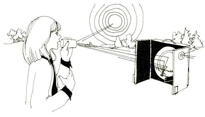
A LITTLE-KNOWN fact about the inventor of the telephone is that Alexander Graham Bell considered an electro-optical communicator he called a "Photophone" to be his greatest invention, greater even than his telephone. In 1880, Bell and Sumner Tainter communicated by voice over a beam of reflected sunlight. This was 19 years before A. Frederick Collins conducted the first feeble voice transmissions over a distance of three blocks in Narberth, Pennsylvania. So, the first "wireless" voice transmissions were not by radio, as history would have us believe.
Compared to the power-hungry radiotelephone medium that developed 25 years after Bell's discovery, the Photo-phone was an elegantly simple technological marvel.
Bell and Tainter succeeded in developing more than 50 ways of voice-modulating a beam of light, including variable-polarization schemes used today in sophisticated laser communication systems.
Photophone Details. The simplest of Bell's and Tainter's modulators consisted of a small flat mirror cemented to a hollow cylinder. Voice energy directed into the open end of the cylinder caused the surface of the mirror to flex in step with the speech patterns. Thus, by shining a continuous beam of light onto the mirror's surface, a variable beam impressed with the voice modulation was produced.
Most of the light-beam receivers used with the Photophone employed selenium detectors. (In 1873, it was discovered that the resistance of bulk selenium changed in response to varying light intensity.) It was after Bell had read about selenium experiments that, in 1878, he conceived his Photophone idea.
One of Bell's detectors consisted of a circular array, while another consisted of a cylindrical array of selenium cells. the first was designed to be used with a collector lens, while the latter was designed to be used with a parabolic reflector.
Both detectors were connected in series with a battery and a telephone receiver to make up the receiving equipment for the Photophone.
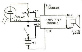
Fig. 1. Schematic diagram of a simple Photophone receiver.
On April 1, 1880, Tainter voice-modulated a beam of sunlight from a mirror and talked to Bell over a 699-ft (213-m) range. After this, Bell made optimistic predictions about the future of his Photophone, none of which materialized during his lifetime. In fact, shortly after Bell's death, in 1921, the Photo-phone was used mainly in a few military applications. Bell was criticized and even mocked for his opinions and predictions. Today, as we are poised on the threshold of large-scale light-beam communication, the inventor has been vindicated. In short, his predictions after all these years are finally materializing.
Build a Photophone. In this Photo-phone Centennial year, Bell's sunlight communication experiments can easily be bettered and duplicated with modern solar cells and audio amplifier modules.
You can start with Bell's simple mirror-and-cylinder transmitter. An excellent choice for this purpose is the $1.65 Cat. No. 30,626 mirror from Edmund Scientific Co. (300 Edscorp Bldg., Barrington, NJ 08007). This mirror measures 25 mm in diameter and nicely mates with a 1" (25.4-mm) diameter tube.
Cut the tube to a length of about 2" (50.8-mm). Then, use white glue to cement the mirror to one end of the tube.
Make certain that the aluminized surface of the mirror is facing outward to obtain best results. (You can determine which is the mirror's aluminized surface by touching both surfaces with the point of a pencil and observing the reflections.
The side that shows no gap between the real and the image points is the aluminized surface of the mirror.) True, the uncoated surface of the mirror is more resistant to scratches and abrasion, but if this surface faced outward, 5% less light would be reflected, which means you would have a shorter communication range.
For more transmitter power, remove both ends from a metal can and tape aluminized mylar or aluminum foil over one end. Or tape a square sheet of either of these reflective materials over a circular hole cut in a sheet of corrugated board. It is important that the surface of the reflector be smooth and taut for best results.
The Photophone receiver can be as simple as a single silicon solar cell connected to the input of a portable audio amplifier. You can salvage an amplifier from a discarded cassette recorder (Fig. 1 shows typical connections) or use a preassembled version such as Radio Shack's new Pocket Speaker Amplifier (277-1008A).
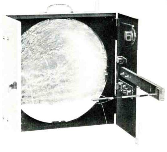
Fig. 2. This receiver can pick up good signals as far as 1/2 mile.
A convenient housing for a basic receiver can be had by modifying a flashlight, such as the Burgess "Dolphin." This flashlight's built-in reflector is an ideal place for mounting a pair of solar cells because it would reflect far more light onto the cells than would be possible if the cells were used by themselves.
Mount two solar cells, back-to-back and connected in series with each other, by their leads with their plane lying along the axis of the reflector. Focus the detector by adjusting the mounting leads while observing their reflections. When the dark surfaces of the two cells fill the entire area in the reflection, the cell detector is properly aligned.
Getting Greater Range. The Photo-phone receiver described above will have a range of up to 550' (168 m). For really long-range communication by sunlight, you can use a large Fresnel lens or parabolic mirror to increase the optical gain of the receiver's detector. A 16" (40.2-cm) reflector-complete with detector, amplifier, battery, and loudspeaker-is shown in a plywood cabinet in Fig. 2. This receiver can pick up good-quality voice and music from as far away as a half mile. Increasing the transmitter's mirror as well, will increase the communication range even more.
You can duplicate this receiver by following the construction details given in Figs. 3 and 4. Make the cabinet from' 1/2 " (1.27-cm) thick plywood, but don't install the doors until later. Paint all inside surfaces of the cabinet flat black and all outside surfaces white enamel. The black in the interior reduces stray light reflections, while the white exterior makes for good visibility during alignment.
The 16" parabolic mirror is available from Edmund Scientific for $19.95 as Cat. No. 80,097. It is aluminized on its rear surface, which prevents it from being a perfect reflector. But the mirror's 1/2 " circle of reflected light at the focal point is about the same size as the photocell, which at least partially makes up for its shortcoming.
Four wood retainers hold the mirror in place inside the cabinet. After cutting these retainers to size, use white glue to cement strips of resilient foamed plastic along one entire narrow face of each.
Then, while the glue is setting, locate and drill the mounting holes for the retainers. By this time, the glue should have set. Paint each retainer block-not the foamed plastic-flat black and let them dry.
Meanwhile, mount a pair of pine legs on the bottom of the cabinet. install the carrying handle on the top of the cabinet, and use white glue to cement a 1"-square piece of resilient foamed plastic in the center of the inside rear wall of the box.
Mount the hinges on the cabinet's doors. Carefully align the doors with the front edges of the side, top, and bottom panels, and mark the locations of the remaining hinge holes. Remove and set aside the doors and drill the holes at the points indicated.
Now, lifting the mirror only by its edges, carefully position it in the cabinet.
Mount the four retainer blocks in place with their foamed surfaces against the mirror's edge. The foamed plastic should be lightly compressed, holding the mirror firmly but gently in place, when all four retainers are fastened down with machine hardware. Once the mirror is in place, exercise care when working around it. Always place a thick bath towel or a blanket over the mirror when you are working on the cabinet.
The detector used in this receiver should be a single 2 x 2-cm silicon solar cell mounted at the end of a hardwood dowel (see Fig. 4). The dowel plugs into a two-section arm made from hardwood stock and hinged at the joint. (The arm is in two sections so that it can be folded to permit the doors to close without obstruction.) Strike a pencil line down the length of the long arm section, centering it on the wide side. Then strike cross lines 1" from one end, and three more lines spaced 1 1/4" (32 mm), 2" (51 mm), and 3 1/4" (83 mm) from the first cross line. At each line crossing, drill a )16" (4.76-mm) hole through the wood. Then use a router, coping saw, or wood chisel to remove all the wood between the first and second and third and fourth holes, making the slots only as wide as the diameter of the original holes.
Butt together the two arm pieces as shown and mount a small hinge at the joint. Use glue and finishing nails to mount a square wood block at the free end of the short arm section. Paint the entire arm assembly flat black. When the paint has dried, drill a hole through the block and arm section, connect 12" (30-cm) lengths of stranded hookup wire to the lugs of a miniature phone jack, and mount the jack in the hole.
After painting an 8 1/4" long by 1/4" diameter (21 cm x 6.35 mm) hardwood dowel flat black and allowing it to dry, mount the 2 x 2-cm silicon solar cell at one end with white glue. Solder stranded hookup wires to the cell's contacts at one end, and connect and solder the free ends of the wires to the lugs on a miniature phone plug. Cut a groove in the side of the dowel to permit the plug's plastic cap to slide over the wire leads.
Remove enough wood from the dowel at the end opposite the cell to permit it to be force-fitted into the end of the plug's cap. With a little care, the dowel will be locked into place when the cap is screwed onto the plug. Use black electrical tape to bind the wires to the dowel in a couple of places.
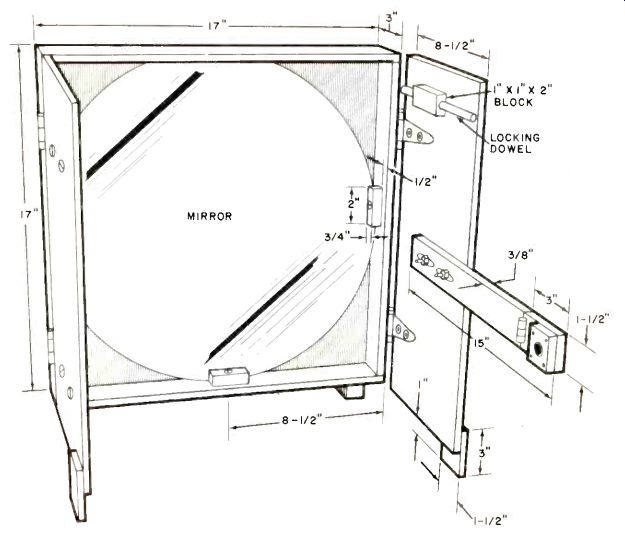
Fig. 3. Dimensions of the plywood cabinet for the Photophone. Mirror
is held in place by wood blocks.
Mount the dowel-and-block assembly that holds the door open at the top of the right door. Position it so that it will not interfere with door closure, and use glue and finishing nails, the latter driven through the door panel into the block.
Make sure the nails do not interfere with free movement of the dowel and the dowel moves freely in the block.
Locate and drill the holes for the detector arm as follows: First, strike a line across the panel midway between the top and bottom of the panel. Mount the door on the cabinet via its hinges. Slide the dowel in the block forward to lock the door open. Direct a strong beam of light on the mirror's surface. Now, plug the detector dowel assembly into the arm assembly and place the arm against the door panel. Center the slots in the arm over the line on the door. Standing out of the way of the light beam, move the arm closer to or farther from the mirror until the reflected light from the mirror just fills the detector cell's active surface area.
Indicate on the door panel's line the points that mark the centers of the slots in the arm. Remove the arm, unplug the detector dowel assembly, and set both aside. Finally, drill a hole at each location indicated. Make the holes just large enough to require that you use a screwdriver to drive a pair of No. 6 x 1 1/2" screws into the holes.
Remove the door panel from the cabinet. Mount plywood legs on the front of both door panels. Then paint the panels, flat black on their inside surfaces and white enamel on their outside surfaces.
When the paint has thoroughly dried, drill perforations for the speaker grille, and mount the speaker on the inside of the panel. Use a metal L bracket for the switched potentiometer and spacers for the amplifier module when mounting them in place. Then refer back to Fig. 1 and interconnect all components.
Anchor the detector arm to the door with large flat washers and wing nuts.
(The wing nuts will facilitate easy focusing of the receiver during field operation.) Bolt the doors to the cabinet with No. 6 machine hardware. Use large flat washers under all screw heads and nuts. Finally, install a hook and eye or lock and hasp on the doors to keep them closed when the receiver is not in use.
Range Testing. Start your testing by fastening the transmitter mirror assembly directly over the speaker of a small portable radio receiver. Aim the beam from the transmitter down a range of several thousand feet where it will not be obstructed. Take the receiver several hundred feet downrange and align its mirror with the transmitter's reflected beam. Plug the detector dowel assembly into the arm on the door and adjust the focusing for the best possible received signal. With proper beam alignment and receiver focusing, you should be able to hear good-quality voice and music transmissions.
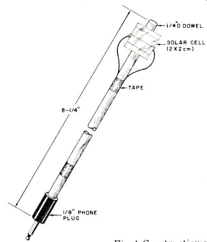
Fig. 4. Construction of final section of detector arm, which is folded to
permit door closing.
Continue to move the receiver away from the transmitter and make reception tests every 50' (15 m) or 100' (30 m) until the signal becomes too weak to "copy." Bear in mind that the earth's rotation will cause the sunlight reflected from the transmitter's mirror to move away from your original alignment point.
So, you will occasionally have to adjust the transmitter's orientation to assure proper receiver/transmitter alignment. I helps if you can recruit one or two friends for the alignment procedure as distances can become quite great.
The maximum range of your system is dependent on the areas of the transmitter's and receiver's mirrors, overall gain of the receiver's amplifier, atmospheric condition, and angle of the sun in the sky. The last is of particular importance because high angles yield far more high intensity than do low angles. Offsetting this is the fact that at high angles, less o the transmitter's mirror surface is utilized than at the lower angles. Consequently there is no way of predicting, with absolute assurance, what the range of you system will actually be.
When the system is not in use, keep the transmitter in a covered box and close the receiver cabinet's doors. Also avoid pointing the receiver toward the sun since concentrated direct sunlight will destroy the solar cell and the detector arm and pose a fire hazard to nearby combustible objects.
Some Modifications. The Photo-phone can be modified in a number of ways to make it perform better. For example, you can increase sensitivity by using light shields and baffles to cut out extraneous light reflections, or you can use a preamplifier to boost the signal level from the solar cell. A large Fresnel lens can also considerably improve receiver operation. Edmund Scientifics’ No. 70,717 ($39.50), 24 3/4" x 19 1/2" (63 x 49 cm) lens has more than twice the collecting area and yields a smaller blur circle of light at its focus than does the 16" mirror.
By using an amplifier module, microphone, and 49-mm-square mirror (Edmund Scientific No. 41,619 at $1.50 each) cemented to the cone of a 2" miniature speaker with white glue, you can put together an excellent voice transmitter that will greatly increase the range of your system.
There are many more possible modifications you can use. With a little ingenuity, you can push the range of your system out to several miles.
For more information about light wave communication systems employing sunlight, LEDs and lasers, refer to "Light Beam Communications" (Howard Sams & Co., 1975).
Also see:
Measure RPM of Rotating Elements with the IC Photo Tachometer