There are six things that every technician needs to know and needs to have for troubleshooting and repairing power supplies. They are:
1. The right test equipment
2. A knowledge of how power supplies work
3. A logical approach to troubleshooting
4. Knowledge of a few "tricks-of-the-trade"
5. The right tools and training for replacing faulty components
6. Experience
Items 1, 2, 3, and 4 are the main thrust of this material and they are covered in this book let. Obviously, Item 5, tools and training, cannot be supplied in any booklet. Also, I've never found a way to provide experience (Item 6) in a text.
We get a lot of letters as a result of our web articles. Among other things, technicians send reports of their experiences. We have put many of their practical ideas into this material. However, there is really no substitute for jumping in and actually doing the work.
TEST EQUIPMENT
Of course, you need a good volt-ohm-milliammeter (VOM) and that an oscilloscope is very useful. A proper set of probes for both is a must.
There are two pieces of equipment that are sometimes overlooked: A good regulated DC bench supply and a good substitute load resistor. Maybe you don't think of them as being test equipment, but, make sure you have them on your bench before you start troubleshooting modem power supplies.
We would like to suggest that you invest in a good commercial DC power supply with built in meters and adjustments. That is easy for me to say, but we know the reality is that some of us may not have the money to invest in such a supply at this time. In that case, put it on your list as a necessary future addition to your bench. Then, build a good regulated supply that you can use in the meantime.
We have included the schematics diagram for two good, yet inexpensive regulated power supplies in Section A. Both circuits are easy to build. Be sure to mount the regulators on a heat sink! That gives the power supplies maximum current capability! All of the information for the home-made supplies is from by Texas Instruments.
The 1N4022 diode in the LM317 illustration isn't always shown in books and articles, but consider it to be an essential part of the supply. Although not shown in the illustration, it would be a good idea to include that diode with the LM350 circuit.
Suppose, for example, that the +48V in the LM317 is switched off and, at the same time, the 25 microfarad output capacitor is fully charged to 25V. That puts a positive voltage at Vout and a lower positive input DC voltage. That reverse voltage across the LM317 can destroy it if the diode is not present! However, under the reverse-voltage condition the diode conducts and places a short-circuit (nearly) across the regulator.
Also shown in Section A is a circuit using the LM350. It has a higher current rating of 3 amperes.
Both of the regulators in Section A will automatically begin to shut down when the output current rating is exceeded. The regulators use a fold-back current circuit. In other words, the output voltage will start to decrease as the output current starts to exceed the current rating. That decrease in voltage can destroy some types of circuits. (For example, TTL circuits, 5V memories, etc.) For that reason we strongly suggest that the power supply voltage be monitored at all times during troubleshooting.
Don't be misled by the simplicity of the circuits in Section A. Both supplies have current limiters and heat sensors to shut the supply down in case of an overload.
It would be a good idea to build several bench-supply circuits so you can substitute all of the voltages into a system that has several outputs.
A substitute load resistance makes it possible to operate the supply you are troubleshooting when it is disconnected from the system. It is not a good idea, and in some cases it is definitely unwise, to operate a system power supply without a load resistance. There is often a minimum idling current requirement for a regulated power supply. That is especially true of regulated DC supplies that use an integrated circuit-regulator. Loss of the idling current can be destructive to the supply and especially to a supply output circuit.
Examples of substitute load resistor circuits are shown in Section B. The illustration also shows how a bipolar power transistor can be used as a substitute load resistance in DC circuits. A Darlington pair (Figure 40) is especially well suited for this application. It can handle high currents but uses a relatively low current for base control.
A V-FET can also be used as a substitute load resistance. As with the bipolar transistor circuit shown, the enhancement-type VFET requires a forward bias. So, the VFET circuitry is similar to the one shown in Section B for the bipolar transistor. It would be a good idea to calibrate the variable resistors for current capability in one-half ampere steps.
Besides using power transistors or series and parallel resistors, another choice is to use a 3-legged regulator mounted on a heat sink.
A combination isolation transformer and adjustable AC power source is a test instrument that will save you many hours of troubleshooting time and make your bench safe. The version made by Sencore (PR57 Powerite) has an AC voltmeter and AC ammeter so you can monitor the input power to a system you are troubleshooting.
With this equipment you can start with a low-input power to the system being serviced.
Then, increase the power while you monitor the voltage and current. If the current starts to increase rapidly you can shut down before any damage is done.
An LCR (Inductance, Capacitance, Resistance) meter can be very useful for evaluating power supply chokes and transformer windings as well as capacitor and resistor values.
The rated capacitance of an electrolytic capacitor is often given with a tolerance of +100%, -50%. Some have even wider tolerances. A measurement of the actual capacitance value of an electrolytic capacitor does not give much useful information.
A meter that measures the ESR (Equivalent Series Resistance) of electrolytic capacitors is an inexpensive and very useful piece of test equipment. ESR is NOT the same as series resistance! Actually, ESR is the equivalent of the combined series resistance and leakage resistance of an electrolytic capacitor.
Many ohmmeters that are part of a VOM cannot accurately measure resistances that are less than few ohms. That is a measurement that is very useful when searching for shorted transformer turns. There are many do-it-yourself circuits available for converting your VOM for making low-resistance measurements.
An in situ tester is a very valuable troubleshooting instrument for locating faulty transistors in hard-wired power supply regulators and other electronic systems. The term in situ means the tester can test a transistor while it is connected into a circuit. You'll not find these testers offered for sale by instrument manufacturers, so, make your own. The schematic diagram for an in situ tester is in Section C. The tester outputs a tone when testing a good transistor.
We have a small desk fan that originally operated on two 1.5V dry cells. WeI use one-half of a center-tapped 6.3V filament transformer and a bridge rectifier to run it because we can never remember to buy batteries.
It has a lot of uses. For example, we use it to blow the smoke away from me when we are soldering. We also use it to move air past a load resistance or power transistor (See Section B) when used as a substitute load resistance across a power supply output.
AN OVERALL VIEW
When you first begin to troubleshoot any electronic system it is a good idea to start with a complete visual inspection. Look for evidence of overheating, burned components, loose wires, defective plugs and connectors, cold solder joints and any other obvious faults. Make the necessary repairs before proceeding. Also, check for a blown fuse or a tripped circuit breaker.
When troubleshooting any electronic system the first measurement should be the power supply [or battery] output terminal voltage. If the power supply output voltage is not correct, fix that problem first. In some cases-such as a low DC output voltage-repairing the power supply will also fix other problems in the system. As will be discussed in more detail later, it is usually necessary to check the output voltage (or, terminal voltage) when the supply is under load.
Let's stop here and make sure we are talking about the same thing when we talk about a power-supply load. The power-supply load is the current delivered by the power supply.
When we say the supply is "under a heavy load" we mean it is delivering a lot of current. The load resistance is the resistance the load current flows through.
If the power supply output voltage is not correct it can cause some other part of the system to stop operating properly. You can waste a lot of time working in a section that seems to be defective when the real problem is in the power supply.
We remember working on an early television receiver that always went out of horizontal sync whenever the power supply voltage was low. If you didn't know that you could spend a lot of time troubleshooting in the horizontal sync section and not solve the problem.
In some modern systems a low [or, high] power supply voltage can destroy a complete circuit, or, components in a circuit. As an example, suppose a technician is troubleshooting in a circuit that is made with TTL logic gates. The technician discovers that several of the gates have been destroyed, so, those gates are replaced. After replacing the gates the circuit is energized and the new gates are destroyed. The real problem was an incorrect power supply voltage.
Of course that seldom happens to experienced technicians, but it does help to explain why the power supply voltage-and sometimes the power supply current--should be investigated as a first measurement in troubleshooting.
This leads to an important rule regarding equipment servicing: Whenever you have made repairs in any system, try to find out what caused the failure before you energize the system again!
The term "power supply" is another term that needs to be reviewed. In many cases that circuit does not actually supply power for operating an electronic system.
Instead, it modifies and controls the amount of power delivered to the system from a DC or AC power [line voltage] source. However, looking from the electronic system toward the power supply, that power supply can be considered to be the power source.
POWER CONVERSION
An important part of power supply technology is the power conversion. Power supplies usually incorporate one or more types of power conversion and it is a good idea to start by reviewing this section of the power supply.
There are four possible power conversions and they are illustrated in Figure 1. They are: AC to AC; AC to DC; DC to AC; and, DC to DC.
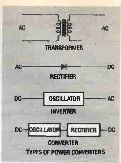
Figure 1
AC-to-AC Conversion
In the AC-to-AC conversion (Figure 1) a power transformer or some other form of trans former is used. A transformer can be used in the following ways:
• Step voltage up or down
• Step current up or down
• Isolate two circuits (as with an isolation transformer)
• Pass one frequency or range of frequencies and, reject all others (as with an RF transformer)
• Match one impedance to a different value of impedance (as with an interstage coupling transformer)
Remember, whenever the voltage is stepped up in a power transformer the current is automatically stepped down and vice versa.
Isolation transformers are a very important part of the work bench in electronics because some equipment is still in use that can prove lethal under the right conditions. That equipment is usually prefixed by the term "AC/DC." In the older systems it is possible to plug that type of equipment into a socket and put the chassis of the equipment at a high-level AC voltage. That is, the chassis is connected to the hot lead of the power cord instead of the ground lead. You do not want the chassis of an AC-DC system connected to the hot side of the AC power line as shown in Figure 2. This can happen, for example, if some energetic home handyman has replaced the plug and/or line cord incorrectly. Even worse, the polarized receptacles on the test bench may be wired incorrectly!
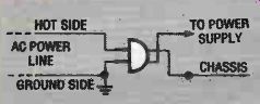
Figure 2
Modern AC/DC equipment has a polarized plug but it is still a good idea to use an isolation system circuit.
An isolation transformer does not convert the voltage from one level to another. Instead, it has a one-to-one turns ratio between the primary and secondary windings. Its only purpose is to isolate the equipment on the bench from the AC power line.
When you are investing in an isolation transformer it is a good idea to put a little more money with the investment and purchase a variable isolated AC power supply with current and voltage meters. This not only isolates the AC/DC chassis for safety reasons but it also permits a technician to determine how much current is being drawn by the system and how much voltage is being applied.
If you have some older AC/DC equipment on your bench for servicing it would be a good idea to change the plug to one that is polarized. Charge the customer for this service. After all, the customer pays you for your expertise, and, preventing accidental death comes well within the range of a technician's capability.
Autotransformers--often referred to by the trade name "Variac"--are not isolation transformers! However, they can be used in the primary circuit of n non-variable isolation transformer to adjust the output voltage to the bench. Some commercial output transformers-like the Sencore type-have an adjustable built-in isolation transformer along with the desired metering.
The second power conversion shown in Figure 1 is a rectifier. Rectifiers "convert" AC power to DC power by limiting the flow of current in one direction only. The theory of rectified by diodes is familiar to even novice technicians.
DC-to-AC Conversion
The third method of power conversion is called an inverter and it is illustrated in Figure
1. It "converts" DC to AC. Remember that every oscillator circuit in electronics is a device that changes DC to AC. A DC power source is required to operate the electronic oscillator and the AC output from an inverter is the result of the oscillation.
DC-to-DC Conversion
A device that "converts" DC to AC is properly referred to as an inverter. Do not confuse it with the converter illustrated in Figure 1. In a converter the DC is changed from one level to a higher DC level. [Resistive voltage dividers are used to change both AC and DC voltages to a lower voltage value]. A transformer can be used to step up the voltage in a converter.
The transformer steps up the AC or pulsating DC voltage. The secondary voltage is rectified and the higher level DC is delivered to the output.
The converter is interesting because it uses three different forms of power conversion that can be built into one unit. The three forms are DC-to-AC, AC to a higher level of AC, and, AC-to-DC. There are many modem power supplies in operation today that utilize several methods of power conversion. For example, a UPS (Uninterruptible Power Supply) is often used in computer systems to prevent the loss of computer memory in the event of a power failure.
The UPS uses a heavy duty battery [such as a lead acid battery] as the source of power. That power must be changed to AC by an inverter.
In the design of the UPS, the AC output must have a very accurate 60 Hertz frequency and must be a pure sine wave. That is why the UPS often incorporates a crystal-controlled frequency, a countdown circuit from a high frequency to 60 Hertz, and, a wave shaping section.
No matter how complicated the electronic power supply design, it will utilize at least one of the methods of power conversion shown in Figure 1.
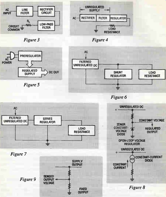
Figure 3-9
NOTES ON UNREGULATED POWER SUPPLIES
A battery is an example of an unregulated DC supply. A simple AC-to-DC rectifier sup ply is another example of an unregulated supply.
An AC-to-DC unregulated supply has no way of maintaining output voltage and/or current at a constant level. It is sometimes called a brute force power supply. An example is shown in block diagram of Figure 3. Since it is unregulated, changes in load will result in terminal voltage changes. In this way the supply behaves like a battery.
When an electronic system operates from an unregulated supply it can be assumed that small changes in the supply output voltage or current will not cause trouble in the system. For example, the normal voltage drop at the output terminals of a battery should not cause dam age in battery-operated equipment.
Percent regulation is a measure of how well an unregulated supply holds its output volt- age when its output current changes. It is calculated using the following equation:
% Regulation = [(No-load voltage -full-load voltage)I(full-load voltage)] x100
where: No-load voltage is the output voltage of the supply with its output terminals open; and, Full-load voltage is the output voltage with its output terminals connected to the normal load resistance of the supply.
Example: The output voltage of an unregulated supply is 25 volts when there is no load resistance connected across its terminals. When the supply is under full load its terminal voltage is 20V. What is the percent regulation?
Solution: % regulation = [25 - 20]/[20] X 100 = 25%
A low value of percent regulation is desirable. Percent regulation is not a term used with regulated supplies.
Unregulated supplies are usually designed to deliver a specific (rated) voltage at a specific (rated) amount of current. To work properly they must be operated at their specified load, or, range of output currents. In most cases you cannot effectively troubleshoot this type of sup ply thoroughly unless it is under load!
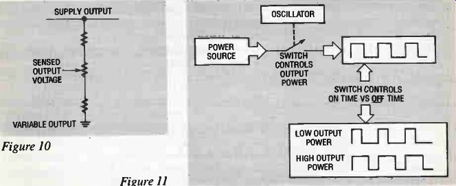
Figure 10-11
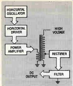
Figure 12
NOTES ON REGULATED POWER SUPPLIES
All electronically-regulated power supply systems have an unregulated power supply as part of their circuitry. (See Figure 4.) A pre-regulator is a form of regulator that is connected ahead of the major regulator. This is shown in Figure 5. A typical example is a regulating transformer. Failure of the pre-regulator to provide a steady output voltage can make it impossible for the major regulator to properly perform its job! Figure 6 shows the connection for a shunt regulator. In this circuit the regulator current is in parallel with the supply load. Usually you will see this type of regulator used in circuits where the power supply must deliver a high current.
Figure 7 shows the connection for a series regulator. In this case the output current flows through the regulator. As a result, this type of regulator is not usually required to pass a very high current.
There are two methods of obtaining voltage and/or current regulation: open loop and closed loop. With an open-loop regulator there is no feedback circuit. The output depends upon a device that delivers a constant voltage (like a Zener diode) or a constant current (like a constant-current diode). Examples are shown in Figure 8. Open-loop regulators are sometimes used as part of a closed-loop power supply regulator circuit! With a closed-loop regulator there must be some method of sensing the output voltage or current. The sensed information is fed back to the supply regulating circuit to control the output. Sense circuits are shown in Figures 9 and 10.
Figure 11 shows two types of closed-loop power supply regulators.
In the analog regulator the supply output voltage is sampled by a sense circuit. The sense output voltage is compared with a reference voltage in the control amplifier. The control amplifier sets the bias on the series pass regulator.
Any change in the output voltage is sensed, and, the control amplifier sets the bias on the series-pass regulator to return the output voltage to the required value.
The switching regulator shown in Figure 11 is switched on and off by an oscillator circuit.
The "on" time is controlled by the feedback circuitry. That, in turn, controls the power sup ply output. Observe the waveforms for low and high output power for switching regulators as shown in Figure 11.
A scan-derived supply is a special case of a switching supply. As shown in Figure 12, it uses the horizontal oscillator to obtain the switching. This type of supply may or may not be regulated.
GENERAL PROCEDURES FOR TROUBLESHOOTING ALL TYPES OF SUPPLIES
It would be a mistake to troubleshoot any type of supply regulator and not take the complete power supply circuit into consideration. Suppose, for example, that a certain supply does not deliver any output voltage. In addition to the regulator circuit, likely causes are a defective transformer or filter inductor.
The arrows on the block diagram in Figure 13 show sections where a supply can become defective. Any of these can be a source of trouble in a regulated power supply.
The problem of troubleshooting power supplies is made a little bit easier by the fact that many of the circuits are common to all types of supplies. You don't have to learn new circuits and new techniques for these every time you troubleshoot a new supply.
We will now look at some common supply circuits indicated by the arrows in Figure 13.
The following discussion includes both theory and troubleshooting techniques.
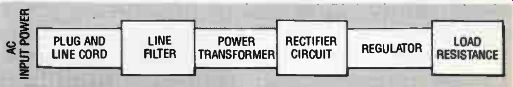
Figure 13
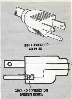
Figure 14
The AC Power Line
Power line problems can occur in both regulated and unregulated supplies.
Don't take the input AC power for granted. There are several types of line voltage problems to consider. The line voltage can be below the standard 120 volts. Also, it could be above 120 volts but that doesn't create as much of a problem. The incorrect line voltage can be for a short term or a long term.
Some regulator circuits will drop out when the line voltage is low. That can be a cause of no output voltage from the supply.
By far the most serious problem with the AC power line is voltage spikes, often called transients. Those spikes can pass through rectifiers, regulators, and, filters and get into the circuitry at the supply output. The result can be insulation or dielectric breakdown, loss of timing in digital systems, and/or a breakdown of operation in any part of the system, and, noise in the system output. This is a very difficult problem because the damage may be already done by the time the technician sees the system. Also, the system may be taken into a shop where there are no line transients and the technician might overlook that possibility.
Here are some suggestions. Always keep the line transient problem in mind-especially if there are components that show signs of insulation breakdown. It might be a good idea to go to the location and look for machinery and other possible causes of transients. In extreme cases you might consider adding a line voltage transient filter such as Transorb to make sure there won't be a call back. I know there are technicians who believe talking to the customer about problems is a waste of time. However, the customer may be helpful in locating possible sources of line transients.
Nearby lightning strikes can induce highly-destructive line transients in the AC power line. I've never talked to anyone who knows what to do about that other than using some kind of transient protective device such as an MOV (Metal-Oxide Varistor). That is always a good idea for your bench AC line-especially in states like Florida where there is a lot of lightning.
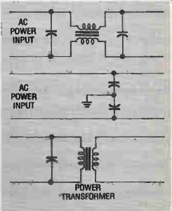
Figure 15
The Plug Could Be the Problem
Don't forget to look at the plug! Start with a good visual inspection. This is especially true if some well meaning handyman has been at work. Remember that the plug in modem equipment is polarized. In other words, it is designed to assure that the ground side of the power line goes to the preferred ground side in the circuit. In some cases the equipment would work with the plug reversed, but some undesirable effects are likely to occur. If it is an AC/DC system there can be lethal voltages on the chassis or other places where you don't expect them.
A second undesirable effect of an improperly polarized input is the likelihood of electrical noise being introduced into the system.
Figure 14 shows a problem that was very difficult to find. The ground connection of the plug was broken internally. This is a safety connection and the customer was without the protection built into the system. There was no symptom to give the technician any hint that there was a problem. However, if someone had been injured or killed you can imagine who would get the blame! Some types of variable transformers used to adjust the line voltage on the bench are made with autotransformers. They give no isolation between the primary and secondary windings! Don't assume those types serve as isolation transformers!! Check them out!!
GOOD WORKBENCH PRACTICE
Equip your workbench with an isolation transformer! The life you save may be your own!!! Line Filters Transient voltage spikes can destroy components, integrated circuits and surface mount devices before an eye can blink. Beyond that, they can produce annoying noise in a system.
Examples of line filters that can be used to get rid of this problem are shown in Figure 15.
They are all examples of low-pass filters. The capacitors short the undesired transients across the line or to ground. Inductors pass the 60-Hertz, power-line frequency but offer a high opposition (reactance) to the high-frequency transients.
Line filters will not protect against the high-voltage spikes created by lightning. Those types require the line protectors mentioned earlier.
Line filters are one of the most neglected parts of any power supply. Even when they are not working properly they may not cause any immediate problem with system operation.
So, they don't get the attention they deserve.
One way to check these filters is to test each component separately. If you are lucky enough to have an LCR tester the components are easy to test. At the very least, use an ohm meter to make sure the capacitors are not leaky or open. Make sure the coils have equal resistance values. Sometimes you can determine if the coils have shorted turns by giving them a close visual inspection. Look for evidence of overheating.
You should make it a habit to check these filters every time you troubleshoot a power supply.
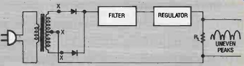
Figure 16
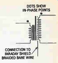
Figure 17
Problems with Power Transformers
The most common symptoms of trouble in a transformer are: overheating, low output voltage, or, high output voltage.
Be sure to measure the transformer output voltage when it is delivering power to the supply circuit, or, artificial load. In other words check it when the supply is under full load. If there are a few shorted turns in the primary or secondary windings they may show up when you measure voltages while the transformer is working.
Resistance checks of primary and secondary windings are usually next to useless unless the manufacturer has supplied the required resistance values. You cannot determine the turns ratio of a transformer using resistance measurements because different wire sizes are used for the primary and secondary windings.
Use the ratio of the output voltage to input voltage (Vout/Vin) to determine the secondary to-primary turns ratio. You may need to know the turns ratio if you have to order a replacement power transformer.
When a transformer is used in a full-wave rectifier circuit, like the one in Figure 16, shorted turns in one half of the secondary winding can cause excessive ripple in the output. The resulting waveform-shown in the illustration-is difficult to filter. However, if the supply has a stiff electronic regulator it may smooth out this ripple problem.
So, if you suspect a shorted turn, disconnect the supply from the regulator at the points marked with an "X." Connect an artificial load resistance (see Section B) across the outputs to ground. Then, using an oscilloscope, look at the waveform across the output terminals.
Here are two important points to remember about transformers with a few shorted turns in the windings: e Shorted turns in the primary winding will cause an increase in the secondary voltage.
• Shorted turns in the secondary winding will cause a decrease in the secondary voltage.
The reason for these changes in voltage is that the shorted turns change the transformer turns ratio.
Remember, an uneven waveform in the rectifier output may be caused by a defective diode. Therefore, if you get the uneven waveform be sure to scope each of the transformer windings (under load) separately.
When you replace a transformer pay attention to the dot notation on the schematic drawings of the circuit and on the symbol (See Figure 17.) They tell which leads have signals that are in phase. Phase isn't always important, so you don't always see the dots on schematic diagrams. When they are included you can assume it is an application that requires the phase notation be followed for correct replacement.
Transformers may have a braided bare wire coming from inside the case. That wire is the connection for the Faraday shield. (See Figure 17.) Its purpose is to reject transient voltages on the line from entering the supply via capacitive coupling between the primary and secondary windings. As with the line filter, don't neglect this shield. It should be connected to a good ground point. However, if the supply has a floating chassis (not grounded) it doesn't do any good to ground the shield to the chassis. Connect it to the power lead that goes to the outside ground. Always check this connection when the system is in for servicing.
Much of the equipment made today has a power transformer that is rated at 50 to 60 Hertz. The reason for that is that some European countries use a 50-Hertz power line in stead of the 60 Hertz we are familiar with in this country. A question that sometimes arises:
If the transformer is rated at 60 Hertz only, can it be operated on 50 Hertz? The answer is that it is not a good idea. The reason being that the lower frequency will see a lower primary winding impedance. That can cause the primary winding current to be too high! In some cases that high current can be destructive to the transformer and equipment it heats up. If a customer asks that question, check it out and, if necessary, replace the trans former with one that is rated from 50 to 60 Hertz.
A remote possibility is that some 400-Hertz equipment will come across your bench.
That would be a rare situation because the power plugs would not (ordinarily) match. however, you should never overlook the innovative genius of the home handyman and the merchandising moxie that is characteristic of flea markets.
Equipment that operates on 400-Hertz power is usually from aircraft and military equipment. The 400-Hertz lines are preferred in aircraft because they permit a lower weight due to the reduced magnetic iron circuitry for the core! Regulating Transformers Some transformers are designed to operate as pre-regulators. Two types are made: self saturating and ferro-resonant. The schematic symbols often used for these transformers are shown in Figure 18. Unfortunately, some manufacturers have slightly modified these symbols. However, you should still be able to determine the type of transformer by comparing their symbols to those in Figure 18. Regulating transformers are sometimes listed by trade names like Paraformer. (See Section D.) The self saturating type is designed so that the magnetic circuit-that is, the core-goes into saturation when the transformer input AC current approaches the rated value. When saturation occurs there can be no further increase in the secondary voltage. That results in the squared tops of the secondary waveform shown in Figure 18.
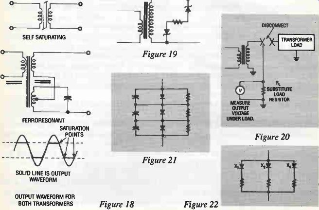
Figure 18-22
This is an example of a case where a low power-line voltage can disrupt the proper operation of a system. These transformers will not work properly unless the primary-winding current is high enough to drive the transformer core into saturation! Since the primary-winding current depends (among other things) upon the impedance reflected from the secondary winding, it follows that the transformer replacement must be an exact duplicate of the original! If you do not use the exact replacement the complete power supply, including the electronic regulator (if it exists) may not perform properly.
If you try to operate a self-saturating transformer without a load it will not regulate the secondary voltage! The ferro-resonant transformer shown in Figure 18 also works on the idea of saturating the magnetic core. However, in this case the core is driven into saturation by the circulating current in a resonant LC circuit.
There is a circulating "flywheel" current in the LC circuit during normal operation. Just before the magnetic field in the core reaches saturation on each half cycle of AC input, the flywheel current in the LC circuit adds enough current (and magnetic flux) to drive the core well into saturation. That squares off the tops of the secondary waveform and limits the secondary voltage.
Every time you troubleshoot a power supply with this type of transformer you should al ways check the inductance and capacity in the LC circuit. You can do this by "scoping" for a near sine wave voltage across the capacitor. (Watch out for high voltages!) Failure of the LC resonant circuit can result in failure of other circuits in the supply. As with the self-saturating transformer, always use a replacement that has the exact same voltage and current ratings.
Figure 19 shows another way of making a regulating transformer. The zener diodes limit the secondary voltage on both half cycles. The result is a secondary voltage that has the same squared-off (amplitude-limited) waveform as the other regulating transformers. Failure of a zener diode may seriously overload the transformer. At the very least, you will get a blown fuse or burned out surge-limiting resistor (to be discussed later.) If the output waveform is OK you can assume the zener diodes are OK. If you get a power supply on your bench that shows evidence of transformer overheating, never energize it to see where the supply is smoking! Disconnect the transformer secondary-winding circuits. Connect a substitute load resistor across the secondary winding then energize it. If the transformer smokes you have two jobs to do: Replace the transformer and find the possible cause of an overload that might have occurred.
Of course, there may not be an overload that caused the transformer failure. However, after the transformer has been replaced it is a good idea to connect the output circuit(s) to a bench power supply one-at-a-time.
For the following test you can usually estimate the current by using the fuse rating. The secondary-winding voltage is usually known from the replacement transformer specifications, or, by measuring it.
When making the transformer test shown in Figure 20, disconnect the transformer at the output leads. Using the rated secondary RMS current (I) and voltage (V), calculate the value of the power resistor: R = V/I. Estimate the resistor power rating by using P = V X I. Then double that value.
I know experienced technicians will write and say they don't have time for all that. If the transformer looks OK and smells OK it is seldom bad, so, better to wrap it up as done.
There's a lot to be said for that because--after all--you have to make a living. However, technicians without a lot of experience may not want to trust their judgment about energizing a circuit with a replaced transformer. Always keep in mind the fact that a circuit can be destroyed by an incorrect DC voltage.
Rectifiers
If you are working on power supplies you already know how the rectifier circuits work.
If you need to review the rectifier voltage ratings, I have put them in Section E. That in formation can be useful if you have to replace a diode and you don't have the specifications.
Remember that you can replace a rectifier diode or bridge with one having a higher voltage and/or current rating. Never use a replacement with lower ratings.
If there is one open diode in a bridge or 2-diode full-wave rectifier, but the other diode(s) are OK, you will get an output waveform that is very difficult to filter. That results in a high output ripple that seems to indicate a defective filter. Before you take the filter apart, use your oscilloscope to look at the rectifier output waveforms.
Remember that a transformer can cause the same symptom, so, check the transformer be fore you squawk the rectifier circuit.
Rectifier diodes might be connected in series or parallel to accomplish a specific purpose. Knowing that purpose tells you something about the supply. For example, they are connected in series to increase the PIV (Peak Inverse Voltage) rating of the rectifier. Series connected diodes usually mean you are working with a high-voltage power supply. Be careful! If rectifier diodes are connected in parallel the objective is to get a higher current-carrying capacity.
Figure 21 shows a typical series connection for diodes. The resistors assure that the reverse voltage across each diode is the same.
There is always a small amount of reverse current through a diode that is reverse biased, so each diode has a reverse voltage across it. The reverse resistances of the diodes are usually not equal, so, the reverse voltages across the series-connected diodes are not equal.
In fact, the reverse voltage across one of the diodes can exceed its PIV rating. That higher reverse voltage can destroy the diode.
The resistors across the series-connected diodes assure equal distribution of the reverse voltage across the diodes. This assumes that the resistors have equal resistances. If one of the diodes has been destroyed be sure to check the resistances of those parallel resistors! In addition to the reverse resistance, a reverse-biased diode has a junction capacity. As with the reverse resistances, the reverse-biased capacities can be unequal. The higher re verse voltage is always across the lowest capacity value. That can happen with a different diode than the one with the highest reverse resistance. The capacitors across the diodes assure equal distribution of reverse voltages across the junction capacities.
You may read that there are other purposes to the resistors and capacitors. The purposes given here are the purposes stated by the manufacturers. They are in the best position to know! The capacitors are not there just to bypass high-voltage transients around the diodes, but, they will do that. Having said that, remember that it is those transient (spike) voltages that are most likely to damage all components.
Not all high-voltage supplies have the reverse-voltage protection shown in Figure 21.
Some have only the resistors, some have only the capacitors, and, some have no extra protection. The line filters discussed earlier are very important for protecting the diodes in the rectifiers.
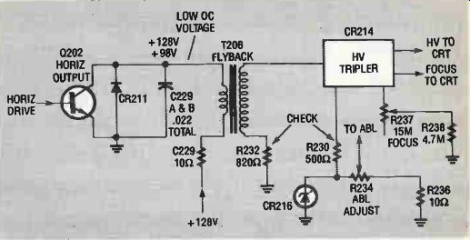
Figure 23
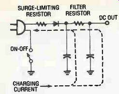
Figure 24
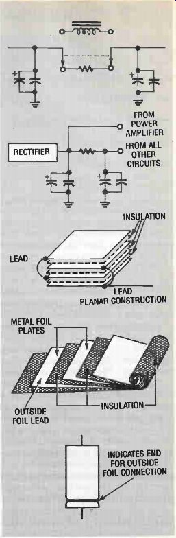
Figure 25
Figure 22 shows how diodes are connected in parallel. It takes a forward voltage of about 0.7 volts across a silicon diode to get it into conduction. That voltage is not written in stone! Some will conduct with less voltage than others. Suppose diode X1 in Figure 22 conducts when there is 0.6 volts across it; and, diode X2 doesn't conduct until there is 0.8 volts across it. Clearly, once diode X1 starts to conduct there is no chance for the other one to get started. This condition is known as "current hogging". The low-values of resistance in series with the diodes assure that there is enough voltage drop across each branch to start the opposite diode(s). As with the line filters, the components in series and parallel-connected diodes are often neglected when the power supply is being serviced. The few minutes it takes to check them can prevent a costly call back or re-servicing job.
There are many packaged rectifier circuits on the market--too many to handle in one monograph. For example, rectifier circuits come in a sealed plastic package with only two leads. For those cases you can't test the individual components. Testing these units is usually for a GO/NO GO evaluation. Even if you could test individual components you couldn't replace them. These packages are tested as a single unit. Treat them as a single diode.
Figure 23 shows an example of the use of a packaged rectifier circuit (CR214). The high voltage tripler in this illustration comes as a single unit. The illustration was taken from an article by Homer Davidson in Electronic Servicing and Technology magazine.
In a typical troubleshooting problem there was insufficient high voltage to the CRT. The horizontal output transistor Q202 was OK but the collector voltage on Q202 measured only 98 volts instead of the required 128 volts. When the packaged high-voltage tripler was disconnected from the secondary the collector voltage of Q202 rose to the required 128 volts.
This very important troubleshooting problem (introduced by Homer Davidson) is a very good example of transformer loading. Any loading on the secondary winding of a trans former is reflected back into the primary winding! So, if the secondary winding is drawing too much current the primary winding will be loaded as described in the above procedure.
The tripler is replaced as a unit and Homer Davidson suggests checking and/or replacing R232 and R230 for possible destruction due to overload.
An important thing can be learned from this troubleshooting problem. Packaged doublers and triplers can go bad in such a way that they draw excessive current and load down the transformer primary winding.
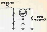
Figure 26
Surge-limiting Resistors
When the power supply in Figure 24 is first energized, the charging current for the filter capacitors--especially the input capacitor--can be amperes high. That will sooner or later destroy the diode. The reason destruction takes time, and a number of on/off cycles, is that the duration of high current is short. However, the diode life will be shortened without the surge limiting resistor. Its job is to limit the diode current while the capacitor is being charged.That way the diode is protected.
The power rating of the surge-limiting resistor is important. With a serious output circuit overload, or a very leaky filter capacitor, the resistor can act like a fuse. Never replace it with a resistor that has a higher power rating! If the manufacturer specifies a surge-limiting resistor-use an exact replacement! If the surge-limiting resistor is burned out check the power supply filter and output circuit carefully.
One way to do that is to connect an ammeter (or, milliammeter) across the terminals of the surge-limiting resistor. The resistor must be removed for this test even if it looks good. Multiply the surge-limiting resistance value by the square of the current.
P = FR
Then, determine if the resistor that was in the circuit has enough power rating to handle the amount of power calculated. In other words, is the power rating of the surge-limiting resistor higher than the actual power dissipated? If yes, replace the resistor and run the equipment for at least a half hour. Is the resistor getting too hot? If so, better check the load circuit.
Let me suggest a very valuable test instrument-a temperature probe. Touching a component to see if it is too hot can lead to very annoying burns. With a little experience you will quickly learn the range of measured temperatures that are characteristic of operating components.
Be especially sure to check the electrolytic capacitors for leakage. As mentioned before, an ESR meter is best for this test.
You may have to disconnect the output circuits of the power supply to find out why the surge-limiting resistor burned out. The ohmmeter is used to locate short circuits, but many current branches may hamper the search for the short circuit. Disconnect all of the supply outputs. Then, connect them one-at- a-time and watch for overheating of the surge-limiting resistor.
Better still, leave the resistor out and the milliammeter connected, and, watch for excessive supply current. If the replacement surge-limiting resistor is overheating, or, there is excessive current, your trouble can be a defective filter capacitor, bad diode, or some problem in the output circuit. After you correct the problem be sure to replace that overheated resistor! Rectifier Output Filters A filter is the next stage after the rectifier. It is often a pi network made with two capacitors and a resistor. An inductor may be used in place of the resistor. Both versions are shown in Figure 25. The advantage of the inductor is that there is practically no DC voltage drop across it, so, more of the supply voltage is available for the output circuit. Also, there is very little power loss in the coil. The disadvantages are higher, greater space requirement, and, the possibility of electromagnetic interference.
At one time the coil was located in a speaker. In that application it was often called a "hum bucking" coil. The coil served two purposes: provide the magnetic field for speaker operation; and, filter the pulsating rectifier current. You may still run across one of these if you service older systems. Their higher cost has resulted in the use of permanent magnet speakers and resistors as filters.
As shown in the second circuit of Figure 25 the power amplifiers in a system are connected so that their high currents do not flow through the filter resistor or inductor. Power amplifiers are not sensitive to voltage changes. So, the less-filtered pulsations do not affect their operation. Also, they require a high current for their operation.
The overall result is that the filter resistor can have a lower power rating when the power amplifier is connected directly to the rectifier cathode. In another version a different supply (with less filtering) is used for the power amplifier. The filter resistor (or, the filter inductor) can be checked with an ohmmeter.
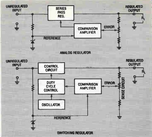
Figure 27
The electrolytic filter capacitors in the second circuit of Figure 25 are shown with low-capacity, non-inductive capacitors across their terminals. Those non-inductive filters are made with the planar instructions. They are sometimes needed because there is a certain amount of self inductance in an electrolytic capacitor. As shown in Figure 25, it is caused by the act that the filter capacitor plates are coiled in order to get as much plate area for a given volume.
The small bypass capacitors must be non-inductive types. Never replace these capacitors with types that have self inductance! The small parallel capacitors make it possible to ground any spike voltages that may have sneaked through the input circuitry. They are likely to be neglected when the supply is being serviced. The reason is that if one of them is open it will not affect the performance of the supply when it is being operated on the workbench. However, if it is returned to service without working bypass capacitors, undesirable transient signals can be passed on to the output circuit of the supply.
Take a few minutes to test those bypass capacitors. Remember to use the right replacement if the capacitor is defective.
Again, the best way to test electrolytic capacitors is to measure their Equivalent Series Resistance (ESR). ESR measures the combined parallel leakage resistance and the series resistance.
Instead of a pi filter, some supplies use an active filter. In this case the word "active" means that an amplifier is used. Figure 26 shows an example. This circuit is also called a capacitor multiplier or electronic filter.
Actually, the circuit of Figure 26 is an example of a stiff (tightly regulated) open-loop voltage regulator. It behaves like a very high value capacitor is being used for a filter.
You will know that the active filter is not working properly if there is too much output ripple voltage, or, no DC voltage at the output. Measure the ripple voltage with your oscilloscope input set to AC. The manufacturer's specification will tell you what the ripple rating is supposed to be. If those specifications are not available, compare the ripple with an other similar circuit. The allowable ripple depends upon the type of output circuit. That is why the value of ripple cannot be given here.
When a good voltage regulator follows the rectifier in a power supply there may be only a single grounded capacitor to serve as a filter. That capacitor often has a very high capacity of 1000 microfarads or more.
If your ESR meter can't evaluate an electrolytic capacitor with a capacity that high, at least use an ohmmeter to look for excessive leakage. It would be better to try an electrolytic capacitor known to be good.
All of the circuitry and components discussed up to this point make up an unregulated supply. Regulated supplies use an unregulated DC source to supply the regulator.