There are essentially only four types of components: tubes (and transistors) resistors, capacitors, and inductors. The variations are numerous - a transformer, oscillator coil, or antenna loop all come under the heading of inductors. The theory of operation of components is presumed to be understood, and, therefore, testing of components will not be a complex discussion.
Replacement of defective component parts requires some thought. There are two types of replacement parts: exact replacement - where the parts are usually obtained from the manufacturer or the manufacturer's local distributor - and general replacement - where the parts are usually obtained from mail-order-catalog supply houses, or local parts jobbers.
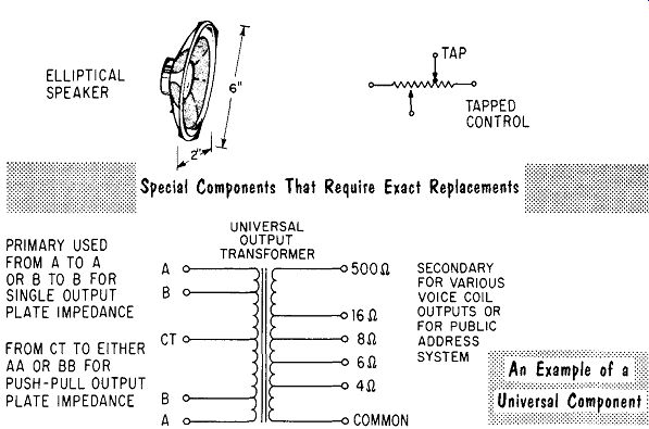
ELLIPTICAL SPEAKER PRIMARY USED FROM A TO A OR B TO B FOR SINGLE OUTPUT PLATE IMPEDANCE FROM CT TO EITHER AA OR BB FOR PUSH-PULL OUTPUT PLATE IMPEDANCE
--------
Exact replacement parts include special shaped speakers used to support a dial, volume controls with special taps, replacement cabinets, etc. General replacement parts include tubes, capacitors, resistors, etc. Also avail able as general replacement parts are specially designed components that are essentially "universal". A typical example is an output transformer with multiple taps to match different output tube combinations.
Any component under suspicion can be tested, as will be explained; however, when in doubt a known good component can be substituted. Substitution of parts indiscriminately is not. the sign of a good technician. Substitution should only be done when either the test is inconclusive or no method of testing is available. An example might be a questionable capacitor and no capacitor checker available. When changing a component with multiple leads, make a penciled sketch of where each wire goes. Do not depend upon memory alone; this can be disastrous.
Resistors
To check a resistor that is wired in a circuit, one end must be unsoldered or lifted. This removes the possibility of a false reading due to a parallel circuit shunting the resistor.
Resistors by themselves cause very little trouble. Occasionally the resistor will change valt1e over a period of time due to heat. When a resistor is charred, burnt to the point where it breaks in half, mere replacement will ...
------
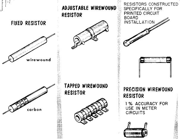
FIXED RESISTOR ADJUSTABLE WIREWOUND RESISTOR TAPPED WIREWOUND RESISTOR RESISTORS CONSTRUCTED SPECIFICALLY FOR PRINTED CIRCUIT BOARD INSTALLATION PRECISION WIREWOUND RESISTOR 1 % ACCURACY FOR USE IN METER CIRCUITS
... not cure the trouble. A resistor itself will not burn up; it chars because too much current flowed through it. Before replacing a burnt out resistor be sure to correct the difficulty that caused the excess current to flow through it.
In replacing a resistor use an equal or increased wattage rating. The tolerance of a resistor should also be matched.
When a resistor is charred beyond recognition and no schematic is avail able to indicate the correct replacement value, similar circuits in the receiver or another receiver can be checked for a typical value.
Controls
Controls are checked with an ohmmeter for continuity and correct value.
One end should be free to prevent shunting by parallel circuits. In checking a volume control one lead of the ohmmeter is placed at the free end and the other ohmmeter lead at the wiper arm connection. The shaft is then rotated to make sure the wiper arm is making contact along the full length of the control.
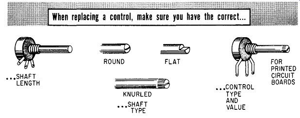
When replacing a control, make sure you have the correct...
----
When replacing a control, the shaft has to be matched in both length and shape. Too short a shaft and the knob will not go on; too long and the knob projects, sticks out too far. Using the wrong shaft will result in a knob that will not fit the shaft. Many controls have the "on-off" switch mounted as an integral part of the control. A defective switch usually means replacing both switch and control.
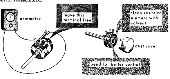
When no replacement is readily available, a temporary repair can be made to a noisy control that has an intermittent wiper arm. The control is removed and disassembled, the resistance element cleaned with a solvent, and the contact arm bent slightly to insure better contact. A small coating of conducting lubricant is then placed on the resistance element, and the control reassembled.
-----------
Tubes and Transistors
In testing tubes a quick and obvious check is for an open filament. An open filament in a parallel heater circuit will show itself in a cold tube.
If the tube is made of glass, a visual check can be made for an operating filament. Portable-radio 1.25-volt tubes will not show any filament light --they cannot be checked by visual means. In a series string of filaments, an ohmmeter can be placed across the heater-tube base pins of the individual tubes as they are removed from the socket.
When a tube is suspected of an intermittent short circuit, it can be tapped gently with a pencil eraser. A complete test of a tube can be made on a tube tester or a known good tube can be substituted for the questionable tube.
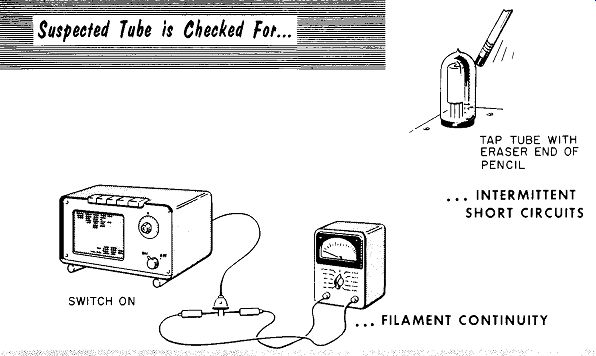
------- SWITCH ON TAP TUBE WITH ERASER END OF PENCIL ... INTERMITTENT SHORT
CIRCUITS
When substituting a glass tube for a metal tube, check the operation of the receiver to be sure it does not need a metal shield. Some tubes are interchangeable with other similar type tubes. Books listing such tubes are published and are available at most parts jobbers.
After servicing a radio, a good idea is to test all the tubes in the receiver and label them: good, weak, etc. This proves to the customer that your work is thorough and may lead to additional tube sales.
In transistor radios, transistors should not be checked except as a last resort, particularly when they are wired directly in the circuit. When a transistor is questioned it should be checked with a transistor checker. If the transistor is defective, the circuit should be checked to insure that the transistor was not ruined by excessive current due to a circuit defect. If this were the case, the replacement transistor would also be ruined.
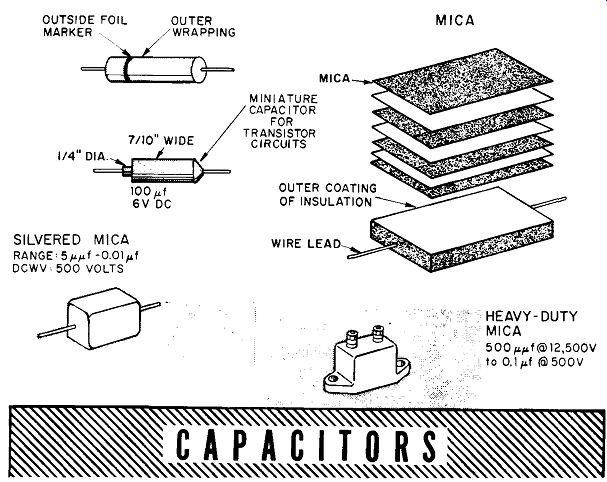
Capacitors
Paper and mica capacitors can be checked while still wired in circuits with capacitor checkers designed for in-circuit testing. To test the capacitors with an ohmmeter for leakage or a short circuit, one end of the capacitor must be unsoldered. This prevents any parallel circuit shunting the capacitor. Often a short circuit will not be indicated with only the low voltage of an ohmmeter applied to a capacitor. It requires the application of full working voltage before the capacitor breaks down. To give the capacitor a proper test for this type of failure, a capacitor checker should be used.
When replacing a capacitor it is best to substitute one with the same rating.
If this cannot be done a slightly higher rating will suffice in most cases.
---
The voltage rating of a capacitor is important. The replacement capacitor should always be equal to, or higher, in voltage rating than the capacitor it replaced. A good practice is to use a 600-volt-rating replacement capacitor at all times, unless size and lack of room forces the use of one with a smaller voltage rating. When replacing a buffer capacitor in an auto-radio power supply, be sure to replace it with a duplicate. When replacing capacitors with an outside foil marking, place the marking to the ground side of the circuit.
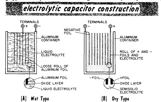
Electrolytic Capacitors
A safe habit is shorting the leads of an electrolytic capacitor; they can store a charge for a long period of time. To check an electrolytic capacitor be sure at least one lead is free of any circuit wiring to prevent a false reading due to a shunt circuit. An ohmmeter can be used for a check of an electrolytic capacitor.
Be careful to observe the polarity of the ohmmeter leads and the electrolytic capacitor. When the leads are placed across the capacitor, the ohm meter will read a low resistance value, followed by an increasing resistance reading, and ending at a higher resistance value, with a typical reading being approximately one-half to one megohm. Electrolytic capacitors show ...
-----
... some leakage, but it should be high - 100,000 ohms or more. The best method of testing an electrolytic is with a capacitor checker where the full working voltage can be applied.
When replacing an electrolytic capacitor, one having a small value can be replaced by one having a higher value. If the electrolytic capacitor is the input filter the increase in value should not be too much, as it may draw too high a value of charging current and damage the rectifier.
The working voltage of the replacement capacitor should be as high or higher than the original unit. When possible the type of mechanical mounting used should be matched. When one section of a multisection electrolytic capacitor becomes defective, it is best to replace the entire capacitor; however, if necessary, the defective section can be replaced with an individual capacitor. When testing electrolytic capacitors in transistor radios, special precautions must be taken. An ohmmeter with low battery voltage should be used since the working voltage ratings of many of the capacitors are as low as 6 volts, with some as low as 1 volt.
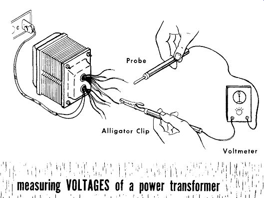
Power Transformers
The reason for a defective power transformer is most often a short circuit elsewhere in the receiver, causing excess current to flow through the trans former windings. After the short circuit is removed, the transformer will have to be tested for damage. To check the continuity of the windings an ohmmeter is used. To check the transformer output voltages, the rectifier and other tubes are removed, and the output voltage values are checked with an a-c voltmeter.
---------
A power transformer that has had an excessive current drain through the windings for sufficient time to have the insulating pitch melt has an unmistakable odor. When this has happened the transformer should be replaced by a duplicate. If a general replacement transformer is used, be sure there is sufficient room to mount it. If the exact ratings of the transformer being replaced are not known, they can be easily calculated. The filament current of each tube is added to provide the total filament drain, plus a 50% safety margin. To figure the B+ current drain, the typical ratings of each tube can be obtained from the tube manual. Note the typical value of plate current listed for each tube. After totaling the typical-value plate currents, be sure to add the 50% safety margin.
To change an auto-radio power transformer, it is best to use a duplicate.
If this cannot be done and a general replacement part is used, check the directions carefully, as a new value buffer capacitor will probably be required.
--------------
Output and I-F Transformers
Defective transformers can be replaced by general replacements
Occasionally the output stage will draw excessive current through the output transformer, opening the primary winding. An open winding can easily be checked for continuity with an ohmmeter. General replacements are often used to replace a defective output transformer, which are available with multiple taps to match any desired impedances.
For receivers having good fidelity, or in high-fidelity amplifiers, it is important that a transformer of equal or better quality is used as a replacement.
An inferior output transformer will reduce the quality of the audio reproduction.
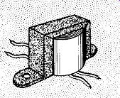
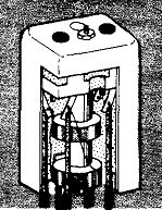
Typical I-F Transformer
I-F transformers of special type or frequency require replacement by a duplicate
------------
Intermediate-frequency transformers with open windings are due mostly to the wire lead from the windings breaking off at either the soldering lug, or where it enters the main winding. An open winding can be checked by an ohmmeter continuity measurement. When the wire breaks off at the lug it can be repaired by cleaning the end of the wire and resoldering it to the lug.
A defective i-f transformer of a special type, or special frequency, requires replacement by a duplicate. A general replacement i-f transformer is suit able in most cases. If the i-f transformer is an input, interstage, or output transformer it should be replaced with a similar unit. When wiring the replacement transformer the leads should be placed in the same positions as the original leads. Care should be used to keep the leads short, particularly the plate and grid leads.
Coils
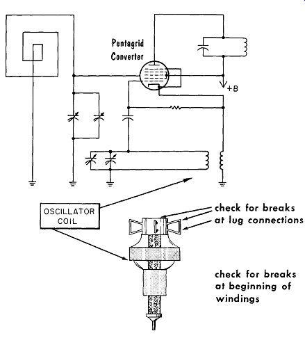
Oscillator coils will open when the fine wire used breaks off either at the connecting lug or at the winding. An open winding can be checked for continuity with an ohmmeter. A defective oscillator coil should be replaced with a duplicate. When using a general-replacement oscillator coil, it will be difficult during realignment to have the oscillator stage track the r-f stage along the entire tuning dial.
--------
OSCILLATOR COIL
Pentagrid Converter
+B check for breaks at lug connections check for breaks at beginning of windings
Loop Antennas
Defective loop antennas with open windings can be repaired or replaced with ferrite-core antennas.
When replacing the loop antenna be sure to mount the ferri-loopstick rigidly and free and clear of the chassis, or any metallic object, such as an i-f transformer. A minimum spacing should be one inch.
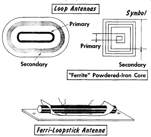
------ Secondary, loop Antennas, Symbol, Primary , Secondary, "Ferrite" Powdered-Iron
Core , Ferri-loopstick ( Antenna )
The Q of a loop antenna can sometimes be changed by pinching together the wires. In some extreme cases, a complete removal of one turn may do the trick. This may be necessary because the antenna has been damaged by an inexperienced technician, or the customer tried repairing the radio himself.
A loopstick, on the other hand, can be adjusted by turning the iron core.
Tuning the antenna is recommended only as a last resort. Ordinarily, it should not be tampered with.
On older sets in particular, the loop antenna is mounted on the back cover.
Care should be taken when removing the cover so that the wire is not pulled from the winding.
Loudspeakers
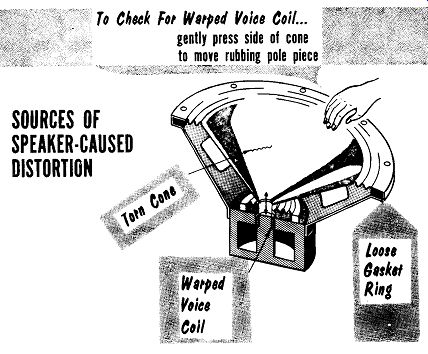
-------- Coil gently press side of cone pole piece
SOURCES OF SPEAKER-CAUSED DISTORTION
Defective PM loudspeakers with no output will have either an open or frozen voice coil winding. An EM speaker with a field coil winding can be checked by carefully bringing a screw driver close to the magnetic field from the front of the speaker (near the voice coil). If there is no magnetic attraction, either the field coil is open or there is no current flowing through the field coil winding. An open voice coil or open field coil is checked by testing for continuity with an ohmmeter.
A speaker cone that is rattling may require re-cementing of the gasket ring at the outer rim. Rattling can also be caused by a torn speaker cone. Speaker distortion may be due to a warped voice coil rubbing the pole piece. To check for a warped voice coil turn the receiver on and gently press one side of the speaker cone to try and move the rubbing voice coil away from the pole piece. If the voice coil winding is open or warped, the speaker cone and voice coil can be replaced. Centering a voice coil on the pole piece re quires some skill. The time taken to do this in the shop may prove to be more costly than the purchase price of a replacement speaker.
A defective speaker with an open field coil may be difficult to replace. If no mounting or space problems are encountered, the speaker may be replaced with a PM type speaker and a separate choke used in place of the field winding. When replacing a defective speaker in a high fidelity receiver or amplifier, it is important that a speaker of equal quality or better is used.
An inferior speaker will reduce the reproduction quality.
There are essentially only 4 types of components: tubes (and transistors), resistors, capacitors, and inductors.
There are two types of replacement parts: exact and general replacements.
To check a resistor wired in a circuit, one end may have to be unsoldered.
In replacing a resistor use an equal or increased wattage rating.
In testing tubes a quick and obvious check is for an open filament.
A tube suspected of containing an intermittent short circuit can be checked by tapping it gently with the eraser at the end of a lead pencil.
When substituting a glass tube for a metal tube, check the receiver operation to be sure a metal tube shield is not required.
A transistor is best checked in a transistor checker.
To test a capacitor with an ohmmeter for leakage or a short circuit, one end of the capacitor must be unsoldered or "lifted." When replacing a capacitor it is best to replace it with the exact value and with an equal or higher voltage rating.
Watch the polarity when checking an electrolytic capacitor with an ohm meter.
Special precautions must be taken when testing electrolytic capacitors in transistor receivers. An ohmmeter with low battery voltage must be used because of the low working voltage ratings of the capacitors.
When changing an auto-radio power transformer it is best to use an exact replacement.
General replacement output transformers usually replace a defective output transformer.
A general replacement i-f transformer is suitable for most replacements.
Most often oscillator coils open where the fine wire breaks at the connecting lug or at the beginning of the winding.
Speaker-cone rattle is often caused by a loose gasket ring at the outer rim or by a torn cone. Distortion is usually due to a warped voice coil.
REVIEW QUESTIONS
1. Describe the difference between exact and general replacement parts.
2. What is a good precaution to take when changing a multiple lead component?
3. What steps must be taken before replacing a charred resistor?
4. A visual test can be made of the filaments of glass tubes other than those used for portable receivers. Explain why.
5. After servicing a radio receiver, what would be a good idea regarding the receiver's tubes?
6. Why is it possible for an ohmmeter check to be inconclusive when testing a capacitor for a short circuit?
7. Describe how to figure the ratings required for a replacement power transformer when the ratings are not available.
8 What precautions must be taken when replacing an output transformer in a high-fidelity audio system?
9. When replacing an i-f transformer, what precaution must be taken with the circuit wiring?