Handling Transistors
Preceding all instructions on transistor receiver servicing, instructions for the care and handling of the transistors themselves is a must. What better way to make a point then through humor? The accompanying illustrations of how not to use transistors speak for themselves.
------------- 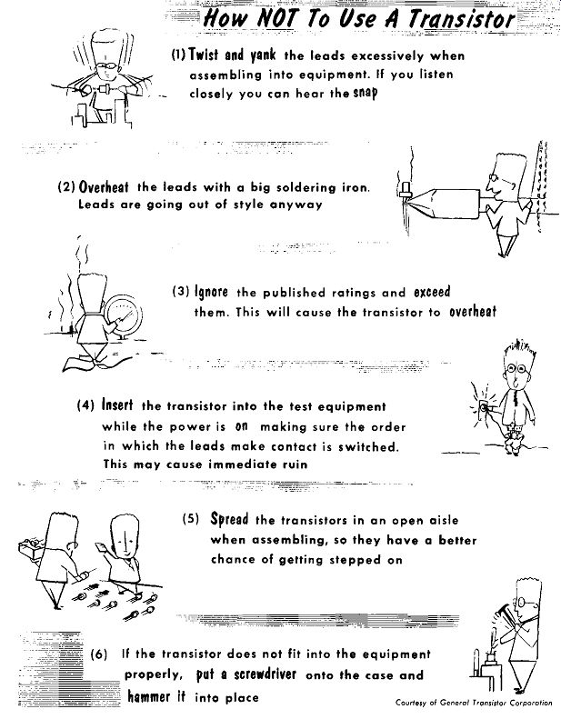
------------ (1)Twist and yank the leads excessively when assembling into equipment.
If you listen closely you can hear the snap.
(2) Overheat the leads with a big soldering iron.
Leads are going out of style anyway
(3) Ignore the published ratings and exceed them. This will cause the transistor to overheat.
(4) Insert the transistor into the test equipment while the power is on making sure the order in which the leads make contact is switched.
This may cause immediate ruin.
(5) Spread the transistors in an open aisle when assembling, so they have a better chance of getting stepped on If the transistor does not fit into the equipment properly, put a screwdriver onto the case and hammer it into place.
Courtesy of General Transistor Corporation
------------ Handling Transistors ( cont’d)
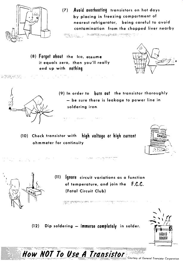
(7) Avoid overheating transistors on hot days by placing in freezing compartment of nearest refrigerator, being careful to avoid contamination from the chopped liver nearby
(8) Forget about the I_co, assume it equals zero, then you'll really end up with nothing
(9) In order to burn out the transistor thoroughly be sure there is leakage to power line in soldering iron.
(10) Check transistor with high voltage or high current ohmmeter for continuity
(11) Ignore circuit variations as a function of temperature, and join the f.C.C. (Fatal Circuit Club)
(12) Dip soldering - immerse completely in solder.
Courtesy of General Transistor Corp.
----------------
Transistor Testing
A vacuum tube, although a sealed evacuated unit, does give some indication as to its operation, if only by the heat, light, or continuity of the filament. This may not be much of a test of the tube's ability to operate, yet it is better than none, and often is a handy check for series string filament circuits. However, with transistors no such quick check is available. Transistors are hermetically sealed units with very little heat radiating from its elements, unless it is a power transistor. As a result, transistors must have some type of tester to indicate their condition. The tube testers used by the average service technician is a far cry from that used in a laboratory, but for servicing of receivers it is adequate. The same condition holds true for transistor testers. The main checks of a transistor consist of determining whether it is open, shorted, or leaky, and whether it has sufficient current gain.
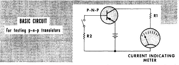
CURRENT INDICATING METER
With the switch in the base circuit open, the battery voltage is placed between collector and emitter in series with a current-indicating meter, and current-limiting resistor, R1. The current flow between emitter and collector will be leakage current. Part of the leakage current is that of Ic0 , the small reverse current, caused by light and heat, that flows in a reverse biased junction breaking up some of the valence bonds. Another determining factor of leakage current is the beta gain found in common emitter circuits. Beta gain is the ratio of a small change in collector current divided by the small change in base current that caused it, which may vary from 10-40 or more. Leakage current between the emitter and collector is roughly equal to I_co times beta. A good transistor will have a small leakage current of only a few microamperes. High leakage current, or a short between the emitter and collector, will provide appropriately high current readings on the meter scale.
Closing the switch in the base circuit will place a small forward bias on the base through resistor R2. The small, emitter-to-base forward bias will result in increased collector-circuit current flow as indicated on the meter.
This permits a rough approximation of the collector-current meter reading to be used as a measurement of beta gain. When a transistor shows no leak age current, and no collector current gain when the switch is closed, it indicates an open transistor.
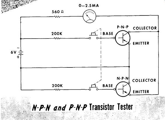
The schematic diagram of a commercial-type junction-transistor tester is shown. Two transistor sockets are provided -- one for the p-n-p type transistors, and one for n-p-n types. The battery is so placed in the circuit as to provide proper polarities for each socket. With no transistor in either socket there will be no drain from the battery. As a result no on-off switch is required. Placing a transistor in the correct socket results in an immediate reading of the meter scale, indicating the transistor's leakage. Pressing the spring-return switch applies current to the base of both transistor sockets. The transistor under test will have a forward emitter-to-base bias applied, resulting in increased collector-current flow. The reading on the meter will indicate the transistor gain, and it should show a gain of not less than one full division (0.25 ma). As previously mentioned, the absence of a reading of either leakage current or gain indicates an open transistor.
N-P-N and P-N-P Transistor Tester
---------
With the exception of laboratory-type instruments, most of the transistor testers on the market have no facilities for testing high-current power transistors. Power transistors require currents of amperes as compared to those of milliamperes for ordinary junction transistors. The meter movements required must be low-resistance high-current ammeters. A meter resistance of one ohm with one ampere flowing, will cause a one-volt drop across the meter. In low-voltage transistor circuits this is prohibitive. The values of the meters required will be dependent upon the type of power transistor under test.
To test power transistors the data supplied by the manufacturer must be used as a guide. Temperature ratings in the area in which the power transistor is being tested should not exceed 25°C. (77°F.). Heat sinks have to be used where specified; if they cannot be used, forced-air cooling with a fan must be used. The high currents used in power-transistor testing requires that extreme caution be used to insure application of the correct polarities to the transistor under test.
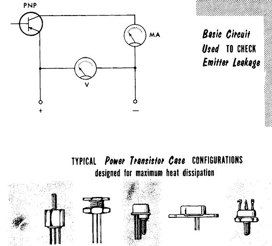
CONFIGURATIONS designed for maximum heat dissipation
----------
A basic circuit to check the collector-to-emitter leakage for a common emitter circuit is shown above. The voltage applied may be from a specially filtered, auto-radio power supply, whose value is determined by the transistor specifications. The voltmeter is used to monitor the applied voltage, and the milliammeter to read leakage current. The leakage-current reading should be taken quickly to prevent any possibility of thermal "runaway", The leakage current should not only be small - it should be steady. A fluctuating leakage indicates a defective transistor. The value of leakage current measured should be referred to the manufacturer's ratings.
Transistor Testing ( cont’d)
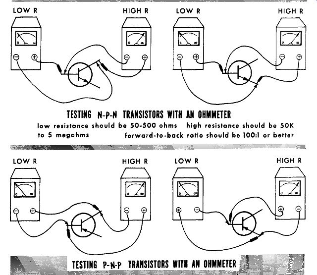
To test a transistor with an ohmmeter, not a shunt type, is an approximate method of testing, but will detect completely-defective transistors. Being performed with the d-c voltages of the ohmmeter, the test gives no indication of transistor gain. Knowing that from base to either the collector or emitter is the equivalent of a diode, we can test the transistor by treating it as two diodes with a common lead at the base.
TESTING N-P-N TRANSISTORS WITH AN OHMMETER low resistance should be 50-500 ohms high resistance should be 50K to 5 megohms forward-to-back ratio should be 100:1 or better
------
To use the ohmmeter (20,000 ohms per volt, or VTVM) certain precautions must be taken: Do not use a shunt-type ohmmeter. Be sure of the polarities of the test leads. Do not use the high (R x 10,000) scale for ohmmeters using a 9-volt, or higher, battery. Do not use the low (R x 1) scale because the ohmmeter current flow may be as high as 0.01 amperes, too high for low-current r-f and i-f transistors. To be safe, use a R X 10 and/or R x 100 scale, depending upon the type of ohmmeter used.
Transistor Testing ( cont’d)
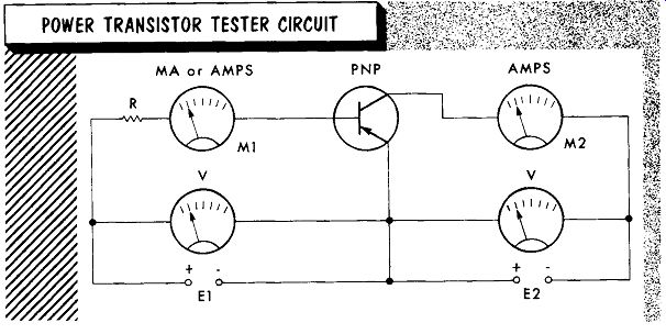
POWER TRANSISTOR TESTER CIRCUIT
-------
The base current, as indicated by M1, should initially be set at zero by application of zero voltage to points E1. The collector voltage as set at E2 should be steady, and at the value given by the transistor data. The voltage applied at E1 is varied in steps, until a maximum value is reached according to the transistor data. Each setting of the voltage at E1 will provide a reading of M1 and M2. The values of base-to-emitter voltage versus base to-collector voltage, and the corresponding base and collector current flow, can be compared to those listed in the manufacturers' ratings or curves. At all times caution should be observed not to exceed the listed ratings.
To test the power transistor for beta gain, the following steps should be taken: (Again a word of caution: do not exceed ratings to any degree or the transistor may be damaged.)
1. Voltage E1 is set to zero.
2. Voltage E2 is set to the rated value.
3. Voltage E1 is increased until the reading of M2 indicates the correct collector current for the rated collector voltage.
4. Voltage E1 is then increased slightly to obtain a slightly increased collector current reading of M2; record this reading.
5. Record the base current indicated by M1.
6. Voltage E1 is reduced to have the collector current reduced from that of step 3 by an amount equal to that used in step 4; record the reading of M2.
7. Record the base current indicated by M1.
Beta equals the difference in collector current as read in steps 4 and 6, divided by the difference in current recorded in steps 5 and 7, being sure that all values of current are the same, i.e., milliamperes or amperes. The majority of power transistors will have a beta gain of approximately 25 to as high as 50.
--------
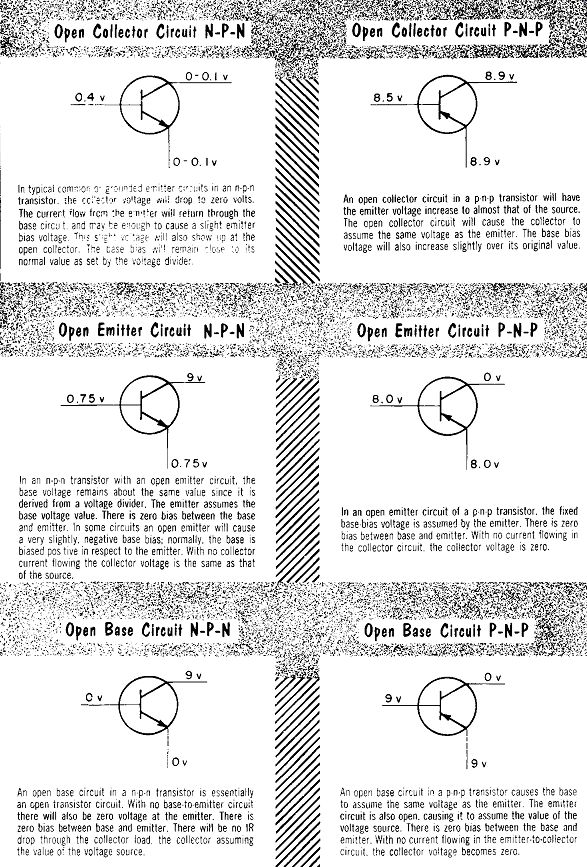
The effect of an open lead within the transistor will be the same whether it is an open base emitter. or collector lead.
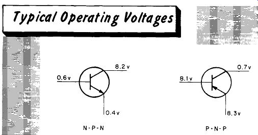
In an open n-p-n with no emitter current flow, the emitter will drop to zero volts. There will be no IR drop across the collector load. and the collector will be at the full source voltage. The base bias voltage will be close to normal value as set by the voltage divider.
In an open p n-p transistor there is no current flow in the emitter circuit: the emitter is at the full source voltage value. With no collector current flowing the collector is at zero volts. The base bias voltage is close to its normal value as set by the voltage divider.
The increased current flow due to a short o, partial short circuit between the collector and emitter in an n-p-n transistor. will cause an increased IR drop across the collector load, reducing the voltage between collector and ground. The increased emitter-current flow will cause an increased IR drop across the emitter resistor resulting in an increased value of emitter voltage. The base bias will remain at its normal value.
The reversal of polarities in a p-n-p transistor with a short between collector and emitter results in an increased IR drop through the collector load. causing a higher collector voltage The increased emitter current causes an increased IR drop across the emitter resistor The base bias will remain at its normal value.
Transistor Operating Voltages ( cont’d)
The open collector circuit will cause the collector to assume the same voltage as the emitter. The base bias voltage will also increase slightly over its original value.
In an n-p-n transistor with an open emitter circuit, the base voltage remains about the same value since it is derived from a voltage divider. The emitter assumes the base voltage value. There is zero bras between the base In an open emitter circuit of a p-n-p transistor. the fixed and emitter. In some circuits an open emitter will cause base bias voltage is assumed by the emitter. There is zero a very slightly, negative base bras; normally, the base is bias between base and emitter. With no current flowing in:
An open base circuit in a n p-n transistor is essentially an open transistor circuit. With no base-to-emitter circuit there will also be zero voltage at the emitter. There is zero bias between base and emitter. There will be no IR drop through the collector load the collector assuming the value o: the voltage source.
An open base circuit in a pn-p transistor causes the base to assume the same voltage as the emitter. The emitter circuit is also open. causing it to assume the value of the voltage source. There is zero bras between the base and emitter. With no current flowing in the emitter-to-collector circuit. the collector voltage becomes zero.
--------------
Power Sources
All transistor receivers operate with various cells or batteries. Penlight, flashlight, and mercury cells in series are a common source of power. An other source is the 9-volt battery. The penlight or flashlight cells are rated at 1.5 volts, and mercury cells at 1.4 or 1.35 volts.
To properly check a battery or cell, it must be tested under load. If a commercial battery tester is not available, take a meter reading of the battery or cell with it placed in the receiver and the receiver turned on. A reduction of 10% or more in a conventional 1.5-volt cell (1.35 volts) or 9-volt battery (8.1 volts) is a sign of a deteriorated cell or battery that should be replaced. A reduction of 5% or more in a mercury cell (1.33 or 1.28 volts), indicates it should be replaced.
---------
Note carefully that a basic assumption throughout all the following transistor receiver servicing notes will be that the battery has been carefully checked and found in good operating condition. It would be pointless to constantly repeat what should be an obvious first step in repairing a transistor receiver - a check of the voltage source.
Despite the advertising claims of "leak-proof" cells or batteries, many receivers will require servicing of badly corroded, battery snap-on plugs or corroded coil holders. Where necessary replace the snap-on plug rather than risk an intermittent or high-resistance connection due to a corroded connector.
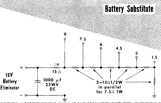
Specially designed power supplies with variable output voltages, and metered to read the receiver current drain are commercially available. A common practice is the use of automobile-radio battery eliminators with additional filtering on the output. A battery eliminator can be used as a replacement or test power source for various voltage values by the addition of an external filtered voltage divider.
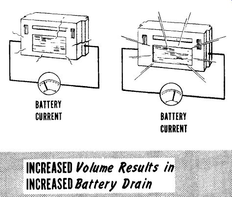
Increasing the receiver volume will correspondingly increase the current drain from the battery. Where a receiver is played with both loud volume and for extended periods of time, battery consumption will increase at a rapid rate. For receivers using push-pull power output, the added current drain of a receiver played at loud volume can be enough to cause a customer to inquire as to the reasons for the increased battery consumption.
BATTERY CURRENT BATTERY CURRENT
------
Despite the low internal impedance of a battery or cell, transistor receivers use an electrolytic, filter decoupling capacitor across the source voltage.
The capacitor value will vary from approximately 50-150 mfd. A defective capacitor can cause motorboating, howling. squealing, etc. by loss of a low impedance path. To check for an open filter capacitor, or a reduction in capacity, bridge the suspected capacitor with a good capacitor of equal or higher capacity. Be sure to use a capacitor with sufficient voltage rating and carefully observe polarities. A shorted or partially-shorted capacitor will cause excessive battery-current drain.
SUMMARY
Proper handling of transistors is important. Physical abuses (improper storage, soldering, handling leads, etc.) and electrical abuses (improper value of applied voltage, improper polarity of applied voltage, etc.) should be avoided.
Transistors, being hermetically sealed units, give no obvious checks for their operation as tubes do; they require a transistor tester.
The main tests of a transistor are for shorted or open current paths, excessive leakage, and current gain.
Testing a transistor with an ohmmeter (not a shunt type) is an approximate method of testing; it gives no indication of transistor gain.
When testing power transistors for beta gain, do not apply voltages exceeding the manufacturers ratings for the transistor.
In testing transistor circuits for correct operating voltages, you should know the approximate values of voltages when the circuit in operating properly. Open or short circuits within the transistor will cause changes that should be recognized.
The voltage readings of properly operating transistor circuits can be compared to readings taken when circuit elements (other than the transistor) are defective, such as open collector loads, etc.
To properly check a battery or cell, test it under load. A reduction of 10% or more in a conventional cell or battery, or a reduction of 5% or more in a mercury cell indicates it should be replaced.
An obvious first step in repairing a transistor receiver is a check of the voltage source.
Specially designed power supplies with variable output voltages, and metered to read receiver current drain are commercially available.
A common practice is to use an automobile-radio battery eliminator with additional filtering on the output.
Increasing the receiver volume correspondingly increases the current drain from the battery.
REVIEW QUESTIONS
1. Describe the proper methods of handling a transistor.
2. What type transistor does give some physical indication as to its operation? How does it give this indication?
3. How do transistor testers used by service technicians compare to those used in laboratories?
4. Describe beta gain.
5. When testing a transistor, what does absence of a reading of either leakage current or beta gain indicate?
6. In testing power transistors, why must the leakage-current reading be taken quickly?
7. When using an ohmmeter to test a transistor, we test the transistor as being the equivalent of what type device?
8. What precautions must be taken when testing transistors with an ohm meter?
9. What is the voltage rating of a mercury cell?