AMAZON multi-meters discounts AMAZON oscilloscope discounts
TESTING superheterodyne oscillator circuits by the signal tracing procedure provides definite and complete in formation regarding the functioning of such systems.
Through signal tracing, obscure faults in oscillator circuits can now be located in a small fraction of the time required when other methods are used.
Signal tracing in oscillator circuits differs from that in other parts of the receiver in that the signal to be checked is generated by the set oscillator and not supplied by an external signal generator. In some sets, the heterodyning oscillator signal is developed by a separate tube and circuit which is coupled to the mixer circuit; in other sets, the functions of the mixer and oscillator are combined within a single tube. No matter which system is used, the purpose of the oscillator is to provide a signal of the proper frequency to combine with the incoming r-f signal in order to enable the mixer to produce the intermediate frequency at which the i-f amplifier is designed to operate.
This is illustrated in the block diagram, Fig. 5-1. In this diagram the r-f signal in the antenna circuit has a frequency of 1000 khz. The intermediate-frequency amplifier is designed for a 450 -khz signal. We can produce an i-f signal of this frequency by tuning the oscillator to 1450 khz. Then, when both the 1000 -khz r-f signal and the 1450 -khz oscillator output are fed to the mixer, a signal representing the difference between 1450 and 1000, 450 khz, is developed in the mixer. Other combinations are possible and the 450 -khz signal likewise would result if the oscillator were tuned to a frequency of 550 khz, which is 450 khz lower than the r-f signal; this is true since the difference between 1000 and 550 would also be 450. In actual practice, though, you will find that most receiver oscillator circuits are designed to operate at a frequency which is higher than that of the incoming r-f signal.
Any amplifier tube may be used as a superheterodyne oscillator and we find in commercial practice that triodes, tetrodes, and action can likewise be performed, but less efficiently, by any of the simpler amplifier tubes.
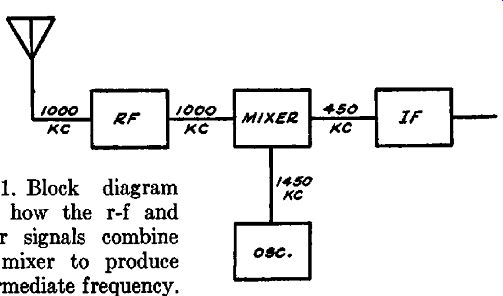
Fig. 5-1. Block diagram showing how the r-f and oscillator signals combine
in the mixer to produce the intermediate frequency.
Fundamental Oscillator Circuits
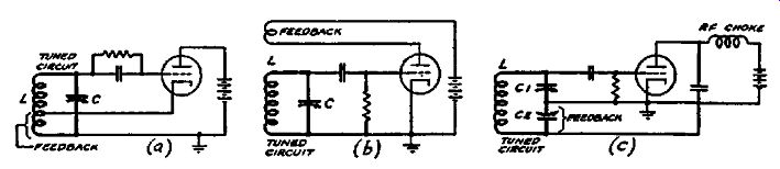
FIG. 5-2. Three basic oscillator circuits. In each case, the feedback winding
is indicated and the tuned circuit which determines the frequency of oscillation
is shown in heavy outline.
A wide variety of oscillator circuits is to be found in broadcast receivers, but actually these are simply minor variations of a few fundamental circuits which are shown in Fig. 5-2. Of these circuits, most sets use either the Hartley shown in Fig. 5-2(a) or the tickler-feedback circuit of Fig. 5-2 (b). In the Hartley circuit, the signal voltage developed between cathode and ground (which is equivalent to the signal voltage between plate and cathode since the plate is by-passed to ground) is coupled back into the grid circuit to produce oscillation. The number of turns above ground at the point to which the cathode is connected determines the amount of feedback in the circuit and consequently governs the oscillator voltage developed. This tap likewise is chosen to produce relatively uniform oscillation over the tuning range of the oscillator. It is important to remember the influence of the tap position with regard to oscillator performance. Some times the wire becomes loose on the coil form so that the amount of feedback is less than it should be. Then the oscillator performance will be affected, causing "dead spots," wide variation in oscillator voltage over the tuning range, poor tracking and mis alignment. These faults may occur in all the circuits shown and are readily revealed in the signal-tracing process.
One of the most widely used circuits is that shown in Fig. 5-2 (b). This is the familiar tickler-feedback circuit, in which a coil in the plate circuit is coupled inductively to the grid coil in proper phase relationship to produce oscillation. The number of turns in this plate coil and the degree of coupling to the tuned circuit determines the amount of feedback. The Colpitts circuit shown in Fig. 5-2 ( c) is seldom used in receivers, though frequently in transmitters. Feedback is obtained by coupling the plate to C1 and the amount of feedback is determined by the ratio of the capacities of C1 and C2. The r-f choke prevents the plate-supply from shorting out the signal across C2. The proper oscillator signal voltage required depends on the type of mixer used and the method of coupling to the mixer circuit. If a pentode mixer is employed, the peak oscillator signal voltage applied to the pentode grid should not be greater than 9 volts when the d-c bias of the pentode mixer is -10 volts. For any other bias, the peak oscillator signal voltage should be one volt less than the pentode grid bias. In pentagrid mixers, such as the 6L7, the peak oscillator signal voltage should not be less than 12 to 18 volts, depending upon the operating voltages of the 6L7.
Any normally obtained value in excess of this minimum voltage is satisfactory.
It is seldom necessary to measure the oscillator peak voltage directly since d-c voltage measurements will give us all the information we need. Let us consider the oscillator and mixer circuit of the Colonial 47, 48, shown in Fig. 5-3. As a result of oscillation, grid current flows through the resistor Rt causing a negative voltage at point 2 with respect to the cathode. This is a pulsating d-c voltage which is caused by rectification of the oscillator signal voltage in the grid circuit of the oscillator tube.
We should expect this voltage to be of the order -10 to -30 volts.
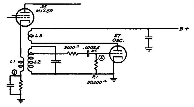
Fig. 5-3. Coupling between the oscillator and mixer sections is obtained
by inductive coupling to the mixer cathode coil.
It is unlikely in any event that the voltage will become too high, since the oscillator circuit is ordinarily so designed that the maximum signal voltage can be developed only when all components of the circuit, including the tube, are new and functioning properly.
Any effects which cause trouble in this circuit normally tend to lower the signal voltage, rather than raise it. The oscillator voltage is coupled into the cathode circuit of the type 35 mixer in this receiver by means of the inductive coupling between coils Lt and LB, the former being in series with the cathode bias resistor for the mixer tube.
Measurements of the d-c voltage across the oscillator grid leak preferably should be made with a very high-resistance voltmeter and a special probe which prevents detuning and loading of the circuit. This probe is described in the section on signal-tracing instruments. It is also possible to make such measurements by opening the oscillator grid leak connection at the low side and inserting a milliammeter (full scale about 1 ma) in series with the grid leak. If the grid leak resistance is 50,000 ohms, the Current through the resistance should not be less than 100 nor more than 500 microamperes. The uniformity of oscillation over the operating range is tested by simply rotating the receiver gang condenser over its range and, with the test instrument connected, noting the variation in the d-c voltage as the oscillator is tuned.
If the tube stops oscillating at any point, the voltage will drop to zero or become positive with respect to the cathode.
Frequency stability is checked by means of a tuned vacuum tube voltmeter which is calibrated in frequency over the operating range of the oscillator to be tested. The check is made by connecting the test probe to some portion of the oscillator circuit where the signal voltage is indicated. The vacuum-tube volt meter is then tuned until its indicator gives a maximum reading.
If the oscillator frequency should change, the tuned vacuum-tube voltmeter will no longer show a maximum indication, but may be returned to a maximum by adjusting it to the frequency to which the oscillator has drifted. The amount of frequency change which takes place may be determined by comparing the initial frequency setting with that to which the voltmeter must be tuned to restore the original indication. Thus, if the oscillator signal frequency were originally 1500 khz and the frequency to which it had drifted were 1600 khz, the amount of oscillator drift is 1600-1500 or 100 khz.
Proper tracking may be checked by signal tracing, not only at the aligning and padding frequencies, but also at any other frequency over the tuning range. By measuring the operating frequency of the oscillator at any setting of the tuning condenser, you can find out if it is tuned to produce the required inter mediate frequency for the incoming r-f signal to which the receiver is tuned.
A tuned vacuum-tube voltmeter is used in making these tests.
This instrument is similar to that employed in making tests by signal tracing in other portions of a superheterodyne receiver ahead of the second detector; it is described in the section on signal-tracing instruments to which we refer you. Its probe is placed sufficiently close to the oscillating circuit to provide enough oscillator signal pickup to give an indication on the test instrument. The signal frequency is then determined by noting the frequency on the dial of the instrument at which a maximum indication is secured.
A Typical Oscillator Test
Let us take an oscillator circuit and check it by this method.
The circuit of Fig. 5-4 is used in the RCA model C9-4 receiver and will serve as an example for practical application of this test ...
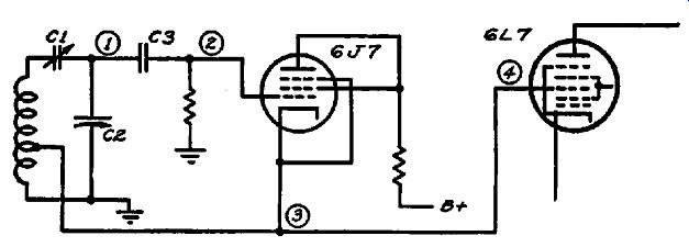
Fig. 5-4. Oscillator circuit used in the RCA Model C9-4.
... system. We shall assume that the receiver is inoperative, yet signal tracing of the r-f signal has shown that the r-f signal is present in the mixer circuit. Our first test is to discover if the oscillator is functioning. This is done by using the isolating test probe to connect our voltmeter from point 2 (the oscillator control grid) to ground and noting if a negative voltage is present. If so, the tube is oscillating and further tests will be required. If the voltage at point 2 is zero or positive, then the trouble is immediately localized in the oscillator circuit and tests of individual components will determine the exact cause.
If we find that the oscillator circuit is functioning, then we should check the frequency with the tuned vacuum-tube volt meter. This is done by placing the test probe adjacent to some point in the oscillating circuit where a strong signal is normally present. This point may be the stator of the oscillator tuning condenser (point 1) or the control grid of the oscillator tube (point 2). The signal voltage will cause the test instrument to give a maximum indication when we tune it to the frequency at which the oscillator is operating. We know that this frequency should ordinarily represent the sum of the r-f signal frequency to which the receiver is tuned and the intermediate frequency employed in the i-f amplifier. If the incoming signal is 600 khz and the i-f 465 khz, then the oscillator should be operating at 600 plus 465 or 1065 khz. If the measured frequency differs greatly from 1065 khz, then we have localized the trouble to some component which affects the tuning of this circuit.
The actual frequency which we measure gives us a good clue to the cause of the trouble. If the padder condenser, C1, is shorted, then the operating frequency of the oscillator will be much lower than 1065 khz when the receiver is tuned to 600 khz.
In fact, we find the oscillator frequency to be only slightly higher than 600 khz, since a short in C1 places all of the capacity of C2 across the oscillator tuning coil. A short in the oscillator tuning coil, or loosening of its turns decreases the inductance of the tuning coil and thereby raises the oscillator frequency to a value higher than 1065 khz. An open circuit in C2, which might result from a broken connection to a stator lug on this tuning condenser, would also increase the frequency at which the circuit oscillates, since then the only tuning capacitance would be the minimum capacitance of the circuit, i.e., the tube input capacitance, and stray capacitance in the wiring.
Minor changes in the measured operating frequency will be caused by misalignment, slight inaccuracies in the measuring apparatus and slight reaction of the test probe on the circuit under test.
Having checked the oscillator frequency, the next step is to see whether the oscillator signal reaches the mixer circuit. In Fig. 5-4, we note that the injector grid of the 6L7 mixer is directly connected to the oscillator cathode. To make certain that the oscillator signal is being fed to the mixer, we may check first at point 3, noting the oscillator signal level at this point; it will be lower in voltage than at points 1 and 2 since it represents only a portion of the total voltage across the oscillator coil. Now we move our test probe to point 4, the mixer injector grid. Since points 3 and 4 are directly connected, the oscillator signal voltage at each point should be the same. If the circuit connecting these points is broken, then we shall find no oscillator signal at the mixer, other than some small indication caused by stray coupling, and our trouble is localized to a simple continuity test. A short-circuit to ground at either point S or point 4 would like wise short out the feedback winding of the oscillator, stopping oscillation. This would be caught in the initial test for oscillator operation.
Other methods of coupling the oscillator to the mixer are also in general use. In Fig. 5-5, the oscillator signal is capacity-coupled through C1 to the mixer cathode. Signal tracing proceeds along ...
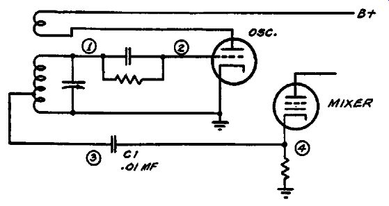
Fig. 5-5. The oscillator signal is coupled into the mixer circuit by means
of the condenser C1.
... the same lines as described above with the following difference that the coupling condenser C 1 should be checked in case there is no signal transfer between points 3 and 4. A short circuit in C 1 will shunt the mixer cathode resistor directly across the feedback tap on the oscillator coil. This may not stop oscillation but it will affect the operation of the mixer tube, since the cathode bias will then be shorted out.
In Fig. 5-6, the path of the oscillator signal is a trifle more involved. The signal voltage is taken from the plate, which is not directly a portion of the oscillating circuit. The plate is electronic ally coupled to the other elements of the tube, but it is possible for the circuit to oscillate normally and yet give very little signal voltage at the plate.
Checking of this circuit ( and others utilizing this form of coupling) involves checking the signal at points 3 and 4 in addition to the tests described for simple triode oscillators. The signal volt- age is normally lower at point 3 than at points 1 or 2, but if there is no signal at 3 then some component connecting to this circuit is at fault. If either R2 or Rt were shorted, such a defect would ...
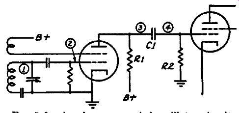
FIG. 5-6. An electron-coupled oscillator circuit.
... result. Shorting of the coupling condenser C 1 would reduce both the signal voltage and the plate voltage at point 3. If the circuit is performing properly, the same signal voltage will be present at both points 3 and 4.
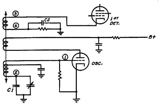
FIG. 5-7. Oscillator circuit with a modified tuned-circuit arrangement.
In Fig. 5-7, the oscillator tuning condenser C1 is arranged differently; therefore, the signal voltage will be a maximum at point 2 rather than at point 1. The oscillator signal is transferred to the mixer by inductive coupling between a coil connected in series with the mixer cathode, and the oscillator tuning coil. The oscillator signal should be present at point S, but not at point 4 since point 4 is by-passed to ground by C2. Some receivers are designed so the desired intermediate frequency is secured when the second harmonic of the set oscillator beats with the incoming signal. When this is the case, it is so stated in the service notes for the receiver. Signal tracing, in the manner described above, can be carried out most conveniently at the fundamental frequency (one-half the second harmonic frequency) since the fundamental is always stronger. In most oscillator systems, though, precautions are taken to keep the harmonics weak in order to prevent them from beating with un desired r-f signals to produce interference or "birdies" on the desired signal.
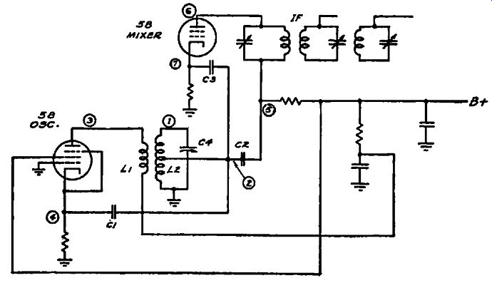
Fig. 5-8. Oscillation is secured by feeding a portion of the signal voltage
in the plate circuit to the cathode of the oscillator tube.
This method of signal tracing is applicable to the most complicated oscillator systems, as well as the simpler ones. In the circuit shown in Fig. 5-8, for instance, oscillation is secured by feeding into the cathode circuit of the oscillator tube a portion of the signal voltage in the plate circuit. This is accomplished through inductive coupling between the plate coil, L1, and the oscillator tuning coil, L2. The close coupling between these coils enables the oscillation frequency to be governed by the tuning of L2, even though the only other point of coupling is to the cathode through C1. This oscillator is coupled to the mixer at the mixer plate and cathode through C2 and C3. Since the control grid is at ground potential, there will be no voltage at this point but the circuit may be checked for oscillation by noting the change in cathode voltage when the tuning condenser, C4, is shorted. This may be done by connecting an electronic or other very high impedance voltmeter to point 4 and ground. If there is no voltage change when C4 is shorted, then the circuit is not oscillating.
The signal may be checked at point 1 and its frequency determined. Tracing the signal from point 2 to point 7 will show whether the coupling to the mixer cathode is effective. The signal voltage at both points should be the same. Likewise the signal voltage should be the same at points 2, 5 and 6, if the plate coupling circuit is in proper operating condition.
In the foregoing, we have outlined in detail the various steps in signal tracing in simple and complex circuits. The information gathered is sufficient to reveal any fault which may exist in oscillator circuits when the receiver is weak or inoperative.
Other oscillator troubles may be present in which additional information may be required regarding the characteristics of the oscillator signal. It is possible that the oscillator signal may not be a pure, unmodulated wave such as is required for perfect operation. If the filtration of the voltage supply for oscillator operation is inadequate, hum may appear on the oscillator signal. This hum will then modulate any r-f signal present in the mixer, though the hum may not appear in the speaker unless the r-f signal is tuned in. Where there is reason to suspect this condition, the hum level of the d-c voltage supplied to the oscillator should be checked. If this is abnormally high, additional filtering should be introduced and its effect on the output of the receiver noted.
If the modulation of hum disappears, then it can be assumed that it was caused by insufficient filtering of the plate supply. In this connection, proper by-passing of the heater is important, especially at the higher frequencies.
It is possible that the oscillator signal may "flutter" due to "motor-boating" in the power supply, or to frequency modulation caused by vibration of some component of the oscillator system such as a loose trimmer or padder screw, variable-con denser plates, microphonic tube, etc. If such a trouble is present, it will be indicated by a corresponding flutter of the indicator on the tuned vacuum-tube voltmeter when the oscillator signal is picked up. To localize the trouble, the power-supply system may be checked by signal tracing while the set oscillator is rendered inoperative (by removing the oscillator tube or short-circuiting the tuning coil). If the flutter is then indicated on the audio testing device, then the oscillator is not at fault.
If the receiver blocks when tuned to a strong local station or when too high a signal is "fed into it from the test oscillator, a variation in power-supply voltage may cause fluctuation of the oscillator voltage and consequently of the oscillator frequency.
Occasionally this trouble also results in "motor-boating." The method of test described above will show whether the trouble is tied in with the local oscillator or elsewhere.
Oscillator circuits also can be checked by substituting the test oscillator for the set oscillator and comparing the receiver performance before and after making this substitution. In this method, the test oscillator is tuned to the required oscillator frequency and its signal is fed into the mixer coupling circuit.
Thus, if the receiver is inoperative and the oscillator is suspected, an antenna is connected to the receiver and the set is tuned to the proper frequency setting of a strong local station. The test oscillator is then adjusted to a frequency equal to that of the local station plus the i-f for which the receiver is designed. If the local station frequency is 600 khz and the set i-f is 465 khz, the test oscillator should be adjusted to 1065 khz. This 1065-khz signal is then fed into the mixer circuit. If the receiver were in operative due to a fault in the oscillator circuit, operation should now be restored. This method is somewhat limited in scope since the maximum output of most service test oscillators is far below that required to duplicate the signal voltage of the set oscillator when it is functioning normally and, further, this method is not as convenient and rapid to apply as the procedure originally described.