One of the first things that comes to mind for increasing enjoyment of tv is to connect more than one tv set to a single tv antenna. This was rather fully covered in Section 6, including sketches on how to hook them up.
Fig. 6-9 in Section 6 shows a mast-mounted splitter, de scribed in that section for use in connecting one antenna to two tv sets, but with the splitter located outside on the mast.
Splitters and couplers are transformers and may be operated in reverse, as well as in the way described in Section 6. The splitter referred to above may be used in another way. Assume you have a vhf antenna because only stations in the vhf channels were in service. Now, a uhf station or two has been added to your city. You can enjoy uhf service without scrapping the old vhf antenna. Just add a uhf front section, like one of those shown in Section 3 ( Fig. 3-5). Bring a 300-ohm twin lead down to the mast-mounted splitter and connect it to one end pair of terminals, connect the vhf lead to the other end terminals, and connect the original 300-ohm lead to the center pair of terminals. The splitter has allowed you to add a uhf section and bring both vhf and uhf signals down the same lead in. Fig. 10-1 shows a sketch of the hookup.
Remember, another splitter will be needed in most cases at the tv set. Most tv sets have two independent sets of terminals for the antenna lead-in connections, one for vhf and one for uhf. A splitter, like the one shown in Fig. 10-2, will divide the signal from the one lead-in into two signals for the two sets of terminals.
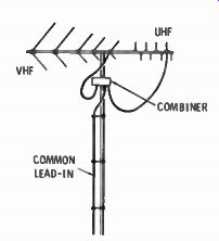
Fig. 10-1. Adding a uhf antenna to a vhf antenna.
COMMON LEAD-IN UHF CONVERTERS
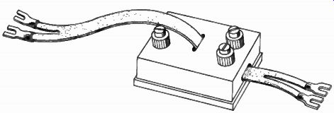
Fig. 10-2. Splitter.
If your set is one of the older types without the uhf bands on it, it will not receive uhf stations even with the proper antenna. But you can enjoy the new uhf service by adding a uhf converter.
The uhf converter changes the uhf station to vhf for use by your tv set. The converter is designed to convert any channel to which it is tuned, to either Channel 5 or 6, whichever is not in use in your city. It has all solid-state circuitry, including a uhf preamplifier before the converter stage, to improve sensitivity.
Fig. 10-3 shows a uhf converter. Fig. 10-4 shows a rear ...
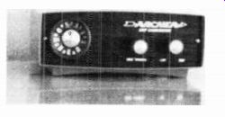
Fig. 10-3. Uhf converter.
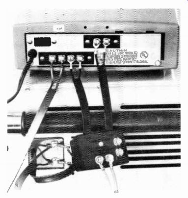
Fig. 10-4. Rear view of converter hookup.
... view with a splitter hooked up to the converter. This splitter was furnished with the Archer vhf/uhf antenna installed. Both vhf and uhf signals are fed separately to the converter. When the converter is off, the vhf leads are connected internally to the output which connects to the tv set. When the converter is on, the uhf input from the splitter, connected to the two upper terminals, is converted to a vhf signal and fed to the tv set.
The sketches of Fig. 10-5. A through D, show the four ways in which the converter may be used with different antenna systems. Illustration B uses the same antenna system as illustration D, but with separate lead-ins. In D, a common lead-in may be used by adding a mast-mounted coupler ( splitter or combiner) such as described previously.
With the converter hooked up and on, and the tv set channel selector on Channel 5 or 6, turn the large knob on the converter until a uhf station is received. The knob on the left of the two smaller knobs is mechanically linked to the large knob and is a fine tuner. It moves the large knob over just a few degrees of rotation.
Fig. 10-6 shows the converter connected to a portable 17 inch tv set. A uhf loop antenna, furnished with the converter, is shown in use. If you are close to a uhf station, this antenna ...
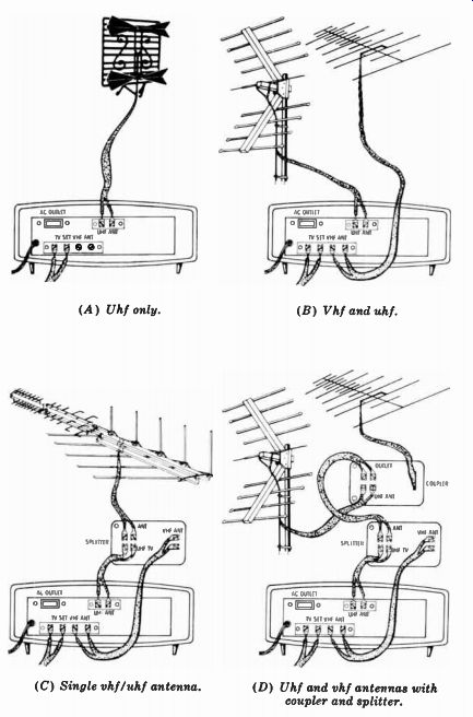
(A) Uhf only. (B) Vhf and uhf. (C) Single vhf/uhf antenna. (D) Uhf and
vhf antennas with coupler and splitter.
Fig. 10-5. Converter installations.
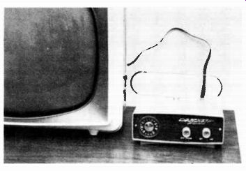
Fig. 10-6. Updating an old tv with a uhf indoor antenna and converter.
...may serve temporarily. Results with it should not be expected to be nearly as good as those from an outside antenna.
INTERFERENCE FILTERS
A most annoying type of interference is that resulting from sparking in electrical equipment. Such sparking can come from the brushes of universal type motors, such as those used for circular hand saws, electric drills, sewing machine motors, etc. It will look like a series of white dots in horizontal lines across a black and white tv set. In a color set, it may look like colored dots in a similar pattern.
Other sparking of an intermittent nature can also cause interference. The make and break of contacts in thermostatically controlled equipment, such as furnaces, electric ranges, etc., can cause occasional bright dots on the screen, usually each time the contact breaks. This is because a slight spark occurs across the contacts of the control element when the current is broken.
Interference of the type described above may enter the tv set in one or both of two ways. It may be picked up by the ac line feeding power to the set, or it may be picked up by the antenna, whichever is closest to the source of interference. A filter may be used at either or both points, that will bypass all or most of the spark pickup and keep it from getting into the tv set. Fig. 10-7 is an antenna-type filter. For use, the antenna lead-in is disconnected from the back of the tv set, and the two leads of the filter are connected to the tv terminals. The lead-in is connected to the pair of screw terminals on the filter. Within the filter is a bandpass circuit that blocks out all radio frequencies above and below the tv frequencies, but allows tv frequencies to pass through. Since interference sparking is at radio frequencies, those that fall within the tv frequencies will get through. However, quite a bit of the spark interference will be blocked, with a resulting decrease in interference.
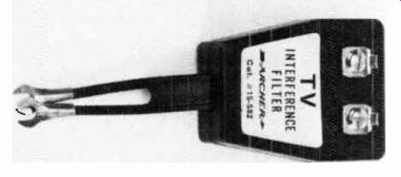
Fig. 10-7. A tv interference filter (antenna).
Next: CB ANTENNAS
Prev: INSTALLING A ROTATOR
AMAZON multi-meters discounts
AMAZON oscilloscope discounts
Also see:
Industrial Electronics (in the early 1960s)
199 Electronic Test & Alignment Techniques (1972)