A no-signal condition does not necessarily mean that there is no sound of any kind present; it means that no signals can be received from stations. There may be a quiet hum from the speaker. Noise radiated from nearby electrical devices, such as fluorescent lights, may be picked up and amplified by the receiver. The identifying conditions for this symptom are that the filaments are lit and no stations can be tuned in.
TEST POINT 1, CHART I
3-1
The block diagram in Fig. 3-1 illustrates the two main sections of a receiver-the section ahead of the volume control, operating at RF and IF frequencies, and the section after the volume control, operating at audio frequencies. The volume control is the entrance to the audio section of the receiver, and injection of a signal here will divide the receiver into its two main sections. If the injected signal is heard from the speaker, the audio section is working and the trouble must be in the RF and IF sections, which are discussed in the next section.
If no sound results from the signal injection, then it is certain that the defect affects the audio section.
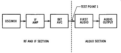
Fig. 3-1. Block diagram of a typical radio receiver.
Any audio signal of 1 h volt or more can be used for the injection at TEST POINT 1. This signal is fed to the center terminal of the volume control, which is turned for maximum volume. Many technicians use the tip of a soldering gun for a convenient source of 60-cycle buzz. A few volts of 60-cycle signal exists on the tip when the gun is on, and this is simply touched to the test point. Even touching the finger tip to the volume control will usually inject sufficient signal to make the test.
TEST POINT 2, CHART I INJECTION OF SIGNAL AT GRID OF OUTPUT STAGE
3-2
If TEST POINT 1 produces no sound from the speaker, or very weak sound, the audio tubes should be checked, and then the testing follows the left side of the chart. The two audio stages can be divided by making a signal injection at the grid of the audio output stage. As seen on the chart at the end of this section, this isolates the trouble into either the audio output or the first audio amplifier. In cases where there is more than one amplifier between the detector and the output stage, the test must be repeated for each stage.
TEST POINT 3, CHART I CAPACITOR FROM PLATE OF OUTPUT STAGE TO B
3-3
If no sound is heard from TEST POINT 2, it is certain that the defect lies in the power supply or in the output stage.
Next, a test is applied which isolates the grid and cathode circuits of the output stage from the other suspects. Fig. 3-2 illustrates the method used.
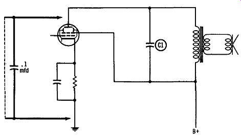
Fig. 3-2. Method used for TEST POINT 3.
The plate can be shorted directly (using a clip lead) if it is done carefully, because the resistance of the transformer limits the current. When the plate is momentarily shorted, either through a capacitor or directly, a "pop" will be heard in the speaker if all the following components are functioning properly.
1. The power supply.
2. The output transformer.
3. The bypass capacitor C1.
4. The speaker.
The explanation of the popping sound heard from the speaker lies in the fact that the uncharged capacitor represents a short circuit for an instant when it is connected. When a wire jumper is used, the "pop" sound is louder. B- is then briefly connected to the top end of the primary winding of the transformer. With B+ on the other end, a large surge of current flows through the primary, creating a magnetic field and inducing current in the secondary speaker. If the output trans former or the speaker has failed, no sound will be heard.
Likewise, no sound will be produced if the power supply has failed. If C1 is shorted, the surge current will pass through it and not through the primary, and no sound will be produced.
The test capacitor should be discharged by shorting the leads together when it is removed, in order to avoid the possibility of accidentally discharging it through the technician's fingers, and also because it must be discharged if the test is to be repeated.
TEST POINT 4, CHART I WHEN A "POP" IS HEARD
3-4
With the knowledge gained from TEST POINT 3, and knowing the tube to be good, the grid and cathode circuits are the only remaining possibilities. Failure in the cathode is more frequent, so this is checked first. TEST POINT 4 uses a clip lead to short the cathode to ground. The cathode resistor can also be checked with an ohmmeter, but this takes more time. Technicians frequently short the cathode pin to the chassis with a screwdriver when the chassis is at B-. Failure of the cathode resistor is common, but many times it is not necessary to make any test at this point because the burned out condition of the resistor is obvious to the eye. However, the importance of making the test is emphasized whenever there is any doubt about the condition of this resistor. If the resistor is open, signals will b~ restored when the cathode is grounded.
3-5
Another important point in connection with measurements at cathodes was mentioned in Section 1. This is that voltage measurements here can be misleading because the tube may draw current through the voltmeter, giving a reading which can appear like correct cathode voltage.
The cathode capacitor does not need to the checked in the symptom of NO SIGNALS, since a shorted unit still completes the cathode connection to B- and will not disable the stage, and an open unit causes only a slight loss of gain in the stage.
Under TEST POINT 4, the cathode resistor is listed as the cause if sound results from shorting the cathode pin of the tube to B-. I<
Procedure When No Sound Results From TEST POINT 4, CHART I
3-6
No sound when the cathode of the output stage is grounded isolates the defect to the grid circuit. Fig. 3-3. Temporary repair of an encapsulated unit.
The resistance from the grid pin of the tube to B- should be checked. It is normally between 250K and 1 meg. Since the grid resistor may be part of an encapsulated electronic circuit, its exact value may not be obvious, and reference must be made to the schematic if replacement is necessary.
Temporary repairs on encapsulated units can sometimes be made in. the manner shown in Fig. 3-3 if only R2 or C2 has failed. If the internal connections between the components or to the external terminals are open, then the entire unit must be replaced. If there is enough space on the chassis, some technicians will install individual parts in place of the unit, rather than waiting until the replacement can be obtained.
Procedure When No Sound Is Heard at TEST POINT 3, CHART I
3-7
Going back to the test with the capacitor from the plate to B-, and assuming this does not produce a "pop" from the speaker, the analysis then continues on the left side of the line under TEST POINT 3.
TEST POINT 5, CHART I SCREEN VOLTAGE MEASUREMENT
3-8
In most receivers, the screen grid of the audio output is connected directly to B+, and measuring the screen-grid voltage provides a convenient check on the power supply. If the screen voltage is missing or very low, it is clear that the trouble is in the power supply.
In Section 2 the symptom DEAD RECEIVER was discussed, and several of the tests used in the power supply were described. In the case of NO SIGNALS where the filaments are all glowing, the testing is simpler. TEST POINT 6 is used to isolate the failure to the AC input circuit or the DC filter.
TEST POINT 6, CHART I RECTIFIER CATHODE VOLTAGE MEASUREMENT
3-9
In this test, the voltmeter is connected to the cathode of the rectifier where the source of B+ can be measured. If a normal reading is found here, the defect lies between this cathode and the screen grid of the audio output. The circuit can be checked for continuity by simply moving the voltmeter probe across each component in series until the voltage disappears. See Fig. 3-4.
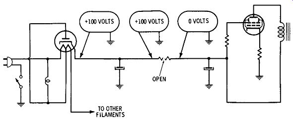
Fig. 3-4. Using a voltmeter to check for continuity in the B + line.
Procedure When the Voltage at the Rectifier Cathode Is Missing
3-10
Voltage missing at the rectifier cathode indicates a failure in the AC input circuit or in the rectifier itself. In transformer-powered receivers in which the filaments are lit, the high-voltage secondary is the only part of the AC input circuit which could have failed. It is also most probable that the failure is in the form of an open winding, so it is simple to check from the plate pins of the rectifier socket to B- for continuity with an ohmmeter. Normal windings will show resistance less than 200 ohms.
Checking the AC-input portion of the power supply in transformerless models in which the filaments are lit is also a simple matter. The ohmmeter is used to check for continuity from the rectifier plate to the AC line plug.
Necessary Tests Before Replacing a Defective Rectifier
With no DC voltage at the rectifier cathode, and the AC input section of the power supply checked out, the defect is isolated to the rectifier itself. But the experienced technician does not jump to the conclusion that only the rectifier has failed. It is possible that some other component associated with the B+ in the receiver is shorted and has caused the rectifier to fail.
Rectifier tubes can be checked on a tube tester if necessary.
Silicon and selenium units can be checked with an ohmmeter by reversing the probes after the first reading and comparing the two resistances, but with larger units this test may be unreliable. The actual value of the resistance readings depends on the amount of voltage supplied by the ohmmeter and is not of much importance in determining the true condition of semi conductors. Direct substitution with a good unit is recommended for silicon and selenium whose peak inverse voltage is 100V or more.
A check should be made of the resistance from the positive side of the filter capacitors to B- before a new rectifier is installed. The familiar "capacitive action" should be seen on the ohmmeter. This is where the meter initially swings to a low value of resistance and then slowly rises to a value of 25K or more if the components are normal. If normal resistance is found, it is safe to install the new rectifier and the surge resistor if necessary.
A low resistance at this point usually indicates a shorted filter capacitor which must be replaced before the new rectifier is installed. The defective capacitor can be isolated by disconnecting them one at a time and rechecking the resistance after each is removed from the circuit. When one of the capacitors in a multiple unit is defective, it is always best to replace the entire unit.
If no shorted filter capacitor is found, the low resistance may be due to a short located somewhere in the receiver circuitry beyond the power supply, and this calls for a more extensive analysis with the ohmmeter.
When a choke is used in the filter network, an ohmmeter check should be made of it to determine if the windings have shorted to the frame. To find a component shorted from B+ to ground in the receiver circuitry, several methods are used.
One way is to check the schematic for the presence of capacitors connected between the B+ line and B-, with no large resistance in series. There will be only a few such components, and each can be checked by unsoldering one end and measuring the resistance again from the positive side of the filters to B-. Another method is to unsolder all the connections at the positive terminal of the output filter capacitor and measure the resistance of each lead to ground. One of the leads will show low resistance, and the technician knows that the faulty part is connected to this line. If tracing this line through the chassis leads to another terminal having multiple connections, this junction must be completely unsoldered and each lead checked with the ohmmeter as before.
Tests Made When Screen Voltage Is Present at TEST POINT 5
3-11
When screen voltage is present and no sound results from placing a capacitor from the plate to B-, the steps to take are shown on the right side of CHART I under TEST POINT 5. The power supply is working, and the cathode circuit is probably intact, because if an open cathode had been the cause of NO SIGNALS, then a "pop" would have been heard when the capacitor was used. With B+ present, the capacitor will produce a noise whenever the speaker and trans former are operative, regardless of the condition of the rest of the circuit.
TEST POINT 7, CHART I PLATE-VOLTAGE MEASUREMENT
3-12
The screen-voltage measurement confirms the presence of B+ and leaves only the output transformer, speaker, and plate bypass capacitor as suspects. The presence of plate volt-age shows that the primary of the transformer has continuity, and attention is immediately turned to the plate bypass capacitor and speaker, as shown on the right side of CHART I under TEST POINT 7.
The easiest way to check for a shorted bypass capacitor is to unsolder one end and operate the receiver. If the capacitor is shorted, sound will reappear-if it is not shorted, there will still be no sound.
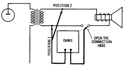
Fig. 3-5. Checking the speaker.
The speaker can be checked with an ohmmeter in the manner illustrated in Fig. 3-5. Open the connection between one OHMS side of the speaker voice coil and the transformer, and connect a probe of the ohmmeter to the voice coil. Connect the other meter probe to the point from which the speaker lead was removed. With the ohmmeter set on the lowest scale, a click will be heard in the speaker if there is continuity throughout the circuit. If a click is not heard, the probe on the speaker lead should be moved to Position 2, as shown in the drawing, and a new test made. If there is still no continuity, the speaker voice coil is open. If there is continuity, then an open secondary winding in the transformer caused no continuity from the first position of the probe.
3-13
If plate voltage is missing and screen voltage present, then the reason for the negative results at TEST POINT 3 is obviously an open primary of the transformer. This should be checked with an ohmmeter. If open, it must be replaced.
TEST POINT 8, CHART I SOUND RESULTING FROM SIGNAL INJECTION INTO GRID OF AUDIO OUTPUT STAGE
3-14
When sound results from injection of a signal at the grid of the audio output stage, it is clear that the fault is in the earlier stages. The analysis for this situation is diagramed on the right side of CHART I. TEST POINT 8, injection of the test signal on the plate side of the grid coupling capacitor, will reveal the condition of this capacitor. If no sound is head, the capacitor is probably open, and a new one should be tried.
3-15
In certain circuits, a shorted plate bypass capacitor in the first audio stages will cause the same results. This is also shown on the chart. Instead of checking the capacitor, the plate voltage of the stage can be measured to ascertain the shorted condition.
TEST POINT 9, CHART I SOUND RESULTING FROM TEST POINT 8
3-16
This condition clearly points to a failure in the first audio stage, and measurement of the plate voltage here will locate faults in the plate circuit. The components which can affect the plate voltage are shown at the left under the heading MISSING PLATE VOLTAGE. The technician expects this voltage to be considerably lower than the other plate voltages in the receiver because of the large plate-load resistor. This was explained in Section 2. Also, the technician will be suspicious if an unusually high voltage or a negative voltage is found here, because this will indicate that no plate current is flowing through the tube. In this case, the analysis moves on to TEST POINT 10, in the lower right corner of CHART I. TEST POINT 10, CHART I SHORT CATHODE TO GROUND
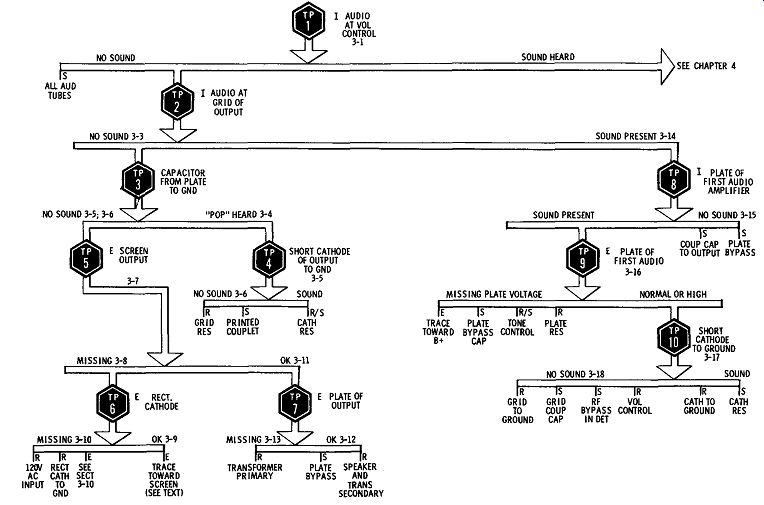

Chart 1
3-17
This is the same test as applied in the audio output stage but, in this case, there may not be a cathode resistor.
Nevertheless, the test should be made, since it is still possible that the connection from the cathode to ground is broken, especially with so-called printed wiring. A clip lead should be used and the cathode pin connected to B-. If sound results from this test, the repairs are simple. If no sound results, -the defect is isolated to the grid circuit of the first audio stage. The resistance from grid to ground should be measured., remembering that it should be several megohms.
The coupling capacitor between the grid and the center tap of the volume control should be substituted. In the case of printed wiring, the continuity of the connections should be checked with the ohmmeter. An ohmmeter check of printed wiring is recommended in all cases where a large component, particularly a control mounted on the printed board, is involved.
The RF bypass capacitor is the one in the detector circuit which shunts the detector load resistor, or the volume control.
A shorted unit here results in a condition in which the volume is very low at both ends of the volume control, but when the control is at the center, stations may be heard weakly. This is a distinctive symptom, and recognizing it at the beginning may save much time.
QUIZ
1. Obtain a receiver which is working normally and short across the volume control. Explain the reason why stations are heard only when the control is set in the middle. What defect is simulated by the short?
2. Why is it not good practice to immediately install a new rectifier when one is found defective?
3. What would be the symptom if C2 in Fig. 3-6 were shorted? What would be the symptom if it were open?
4. Under what conditions could C3 in Fig. 3-6 prevent a signal from being injected at TEST POINT 8?
5. What additions should be made to the right side of SERVICING CHART I to cover push-pull stages?
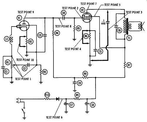
Fig. 3-6. Test points in audio section and power supply.
6. The following tests were performed on a receiver with the NO SIGNALS symptoms:
1. Audio injected at TEST POINT 1 produced no sound.
2. Audio injected at TEST POINT 2 produced no sound.
3. TEST POINT 5 showed zero volts.
4. TEST POINT 6 showed 100 volts.
State one component in Fig. 3-6 which could be defective, and describe the tests you would make to find it.
7. A receiver has the NO SIGNALS symptom, and when the technician placed a capacitor from the plate of the output tube to ground, there was no noise in the speaker. List all the parts which could have failed.
8. Look up the schematic of an amplifier which uses resistance coupling into a push-pull output stage. Describe the symptom and the test necessary to identify a faulty component which does not appear in SERVICING CHART I or in Fig. 3-5.
9. Name four components in Fig. 3-6 which, if they were open, would not affect any DC voltages.
10. Several components in Fig. 3-6 are not mentioned on SERVICING CHART I. List as many as you can find.
11. Select one of the components in your list in Question 10, and describe the symptom and all the tests necessary to find it.
12. If C6 in Fig. 3-6 were shorted, list in the proper order all the tests and the results of each necessary to locate it.
13. A receiver has the NO SIGNALS symptom and the technician performed the following tests in this order:
1. Audio injected into the center of the volume control produced no sound.
2. Audio injected into the grid of the output stage produced no sound.
3. Plate voltage on the output stage measured 0 volts.
4. Cathode voltage on the rectifier measured 100 volts.
5. C7 and CS were checked with an ohmmeter and found to be 50K.
6. R9 measured 1500 ohms, which was correct.
The technician was stumped because he had not followed a logical procedure. What mistakes did he make?
14. What is the next test you would make after finding 15 volts on the plate of V1 in Fig. 3-6?
15. Draw a circuit of an audio voltage amplifier with a tone control, and explain how a component in the tone-control circuit could cause a NO SIGNAL condition.