In this Section we will cover operation and troubleshooting information on various electronic tuners used in assorted makes of color TV receivers.
The circuits will include the VHF and UHF tuners along with their control center circuits. Some will be the manual channel selector control units, while others will be remote controlled via all electronic switching IC and transistor devices. Various DC voltage control and AFC (automatic frequency control) circuit schemes for electronic tuners will be reviewed.
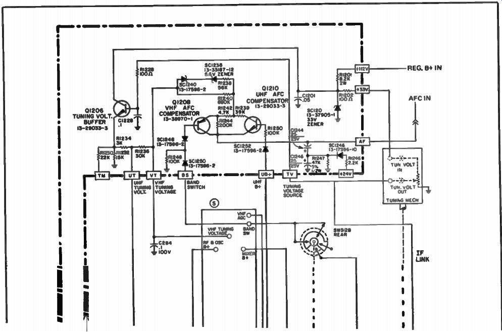
Fig. 1. Sylvania manual control electronic tuner system.
THE SYLVANIA MANUAL ELECTRONIC TUNING SYSTEM
Some Sylvania color sets have conventional two knob UHF and VHF tuning systems, but others have a combination UHF/VHF varactor tuner with a one knob addressing system. One channel selector and one fine tuning knob are used to change and adjust both UHF and VHF stations.
The tuning voltage applied to the UHF/VHF tuner is varied in two ways. Note the tuner control circuit shown in Fig. 1. Band switches apply the 24 volt B+ line to either the UHF or VHF portions of the tuner.
The variable tuning voltage comes from the 112 volt B+ line and is dropped and regulated by a 33 volt Zener on the tuner cluster assembly.
This 33 volts is varied by adjusting variable resistors mounted in a tuning assembly that looks like a small barrel type tuner. Instead of many contacts on each of the strips, as with a conventional barrel type tuner, these strips have only three contacts on the variable 10 K ohm resistor. The voltage output from the variable resistors, ranges from +1 volt to +28 volts. As the channel selector is rotated, a different dial appears through the viewing window. This dial indicates the channel ranges in either the UHF or VHF spectrums. As the fine tuning knob is varied, a red pointer moves up and down the indicator dial showing the channel being tuned. This dial is located below the channel knob. A second channel indicator window is visible above the channel knob. It indicates all of the VHF channels and has positions to insert the UHF channel numbers that the set will be tuned to in the viewing area. Once the channels have been programmed, the viewer turns the channel selector until the desired station number appears in the top viewing window.
In addition to varying the tuning voltage with the variable resistors, the tuning voltage is also varied slightly by the AFC system. The AFC voltage is applied to a printed circuit board mounted on the tuner cluster that has the various circuits required to drive the varactor tuner. The AFC voltage is fed to Q1208 the VHF compensator and Q1210 the UHF AFC compensator. The output of these two transistors varies the tuning voltage slightly to produce automatic fine tuning action.
The output of the varied 33 volts from the addressing turret is applied to Q1206 the tuning voltage buffer transistor. The output of this emitter follower transistor is varied slightly by the AFC system and then applied to the varactor tuner itself.
The RF AGC voltage from the set is applied to Q1201 the AGC converter transistor and Q1204 the UHF AGC driver transistor, both of which are mounted on the PC board on the tuner cluster. The RF AGC voltage outputs of these two transistors are fed to the UHF and VHF sections of the varactor tuner.
The AGC voltages measured with a signal (the set tuned to a local station) and without a signal (the set tuned to an unused channel) are RF AGC input +8 volts with signal, +4 volts without signal. VHF tuner input +4 volts with signal, +8 volts without. UHF tuner input +4 volts with a signal and +9 volts without a signal.
ZENITH DIRECT ACCESS TUNING SYSTEM
Looking at the block diagram in Fig. 2, you will see seven major block sections that are required to make the direct access tuning system operational. As you may guess, the heart of the system is the new microprocessor module. This A-7892 module consists of six integrated circuits and 13 transistors with all of the associated circuitry. The 175-5104 direct access tuning unit package consists of the new micro processor module (A-7892), keyboard channel selector, prescaler, and the space command remote receiver. There is also a manual version of this direct access tuning system.
Channel Selection Operation
The receiver-mounted keyboard consists of 15 snap-action push buttons. This type of push button switch offers a positive user feel and has the following features:
• Separate on/off buttons (button must be held a moment for on/off action).
• 0 to 9 channel selector buttons.
• Separate volume up/down buttons.
• Enter button.
A channel can be selected by pushing the desired channel number and then pressing the enter key. Also, a 0 does not have to be entered for a single channel number. If a channel number is selected without pressing the enter key, the display will show the new number, but will return to the original number after 4.5 seconds have elapsed.
This direct access system will also tune the cable TV channels that are referred to as the super band channels J through W and the mid-channels A through I. The mid and super channels are tuned on channels 14 to 36.
Direct Access Functional Blocks
As we know, the microprocessor IC is the heart of this complete tuning system. It is essentially a small computer which controls all of the functions of the tuning system.
• It constantly scans the receiver mounted keyboard looking for a contact closure.
• It constantly monitors the remote receiver output looking for a remote key closure.
• It controls the operation of the LED channel display through a decoder/driver IC.
• It provides B+ switching and bandswitching for the VHF and UHF tuners.
• It controls the operation of a phase-locked-loop IC which results in precise control of the tuner oscillator frequency. See Fig. 3.
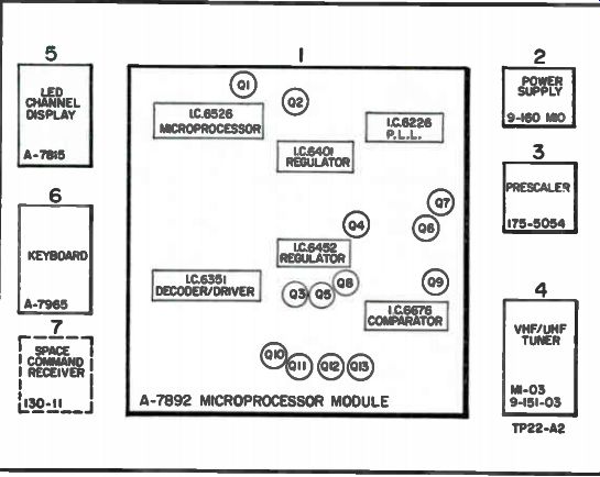
Fig. 2. Direct access system block diagram.
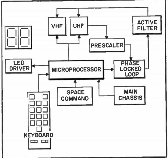
Fig. 3. Functional block diagram of direct access system.
Phase-Locked Loop Operation
This tuning system is referred to as a frequency synthesis tuning system. In a voltage synthesis type, a precise, stable tuning voltage is generated and used to control the tuner oscillator. This type of system depends heavily on conventional AFC operation for oscillator frequency stability.
In a frequency synthesis system, a precise frequency is generated and maintained. When a channel is selected, the microprocessor knows what the correct FCC designated frequency should be for that channel. It develops a tuning voltage that will put the oscillator at the correct frequency. It constantly monitors the oscillator frequency by dividing, counting and comparing it to a reference, which results in automatic correction of the tuning voltage, assuring oscillator stability.
As you will note in Fig. 4, a crystal-controlled oscillator, operating at 3.581055 MHz, is divided by a 14 stage reference divider in the phase-locked-loop IC, to provide an output frequency of 976.5625 Hz. This frequency, rounded off to 1 kHz, becomes the reference base which is applied to one input of a comparator.
The VHF or UHF oscillator frequencies are applied to a prescaler circuit. This prescaler IC and its associated circuitry, is required because the normal VHF and UHF oscillator frequencies for each channel are much too high to be used as a comparison in the phase-locked-loop IC. The prescaler drives the oscillator signal down by 256.
Referring to Fig. 4 again, we see the divide-down oscillator signal is applied to a programmable divider in the phase locked loop IC. Here, it is further divided by a variable ratio, to produce an output frequency which becomes the second input to the comparator. The comparator produces an output which is dependent on the differences between the crystal controlled reference signal and the divided down oscillator signal.
The comparator output is a series of pulses with variable duty cycles.
These pulses are fed to an active filter circuit. The active filter smoothes these pulses and produces a DC output with a negligible amount of 1 kHz ripple. This DC voltage is in fact the tuning voltage which is applied to the varactor diodes in both tuners. In this manner, the tuner oscillator assumes the stability of the crystal reference.
In order for the comparator to operate correctly, the two input frequencies (tuner oscillator and reference) should be about equal (1 kHz). Since the oscillator frequencies are different for each channel, a different divide ratio must be used for each channel. For example, the channel 2 local oscillator frequency is 101 MHz. In order to yield a 1 kHz output, the signal must be divided by 101,000. The channel 13 local oscillator is at 257 MHz. This frequency must be divided by 257,000 to produce the same 1 kHz signal. This task is accomplished in the programmable divider.
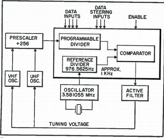
Fig. 4. Phase locked-loop block diagram.
The divide ratio is determined by information provided by the microprocessor via four data input control lines. Each time a channel is selected, the microprocessor will put the correct binary control signal on each of the four input lines to establish the correct divide ratio for that particular channel.
Three data steering input lines are used to determine to which internal registers the binary signals belong. The microprocessor performs many other functions besides controlling the phase-locked-loop IC. Because of this, there may be information on the control input lines which is not meant for the phase-locked-loop IC. The eighth input from the microprocessor is the enable. Information on this line permits the phase-locked-loop IC to receive the correct data and exclude all other information.
The 1 kHz pulse width modulated output from the phase locked loop IC is applied to the base of Ql. A Darlington stage is used here to maintain an extremely high input impedance. The output of the collector of Q2 is fed back to Q1 via C14, C15 and R67. This filtered DC voltage at the collector is then routed through Q12, an emitter follower, to provide a low impedance drive to the tuner.
Connected to the base of Q12 is an adjustable clamp circuit. This circuit does not allow the tuning voltage to go below 2.25 volts DC on the high VHF or mid-band CATV channels. Misadjustment of this clamp circuit can cause the tuner oscillator to stall, ultimately making the system to lock-out.
The clamp voltage is set by a potentiometer located on the A-7892 microprocessor module.
The correct adjustment procedure is as follows:
• Set the mode switches to normal.
• Select a high (7 to 13) channel.
• Remove the shielded cable between the VHF tuner and prescaler.
• Adjust the potentiometer for 2.25 volts DC on the tuning voltage line.
• Reconnect the shielded cable.
Keyboard Scanning
The microprocessor constantly scans the keyboard by sending pulses on three output scan lines. See Fig. 5. These lines are arranged in such a way as to represent the vertical, or x axis of the keyboard (three vertical rows of keys). The horizontal, or y axis of the keyboard is represented by five output lines. When a key is depressed, the appropriate x -y contact is made. The contact closure transfers the pulse back to the microprocessor via one of the five output lines. The microprocessor detects the pulse, producing the desired digit on the display.
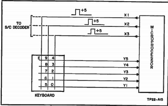
Fig. 5. Keyboard scanning block diagram.
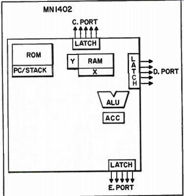
Fig. 6. Microprocessor organization diagram.
Microprocessor Organization
All of these circuits are controlled by a microprocessor which is essentially a small computer. The internal organization of the micro processor is shown in Fig. 6. The microprocessor consists of four major sections:
• The arithmetic logic unit (ALU) performs a sequence of operations determined by commands which are stored in various memory locations. It can do additions, subtractions, comparisons and so forth. It performs these operations one at a time.
• The accumulator (ACC) section of the IC is used by the (ALU) to temporarily store information while it performs its various duties.
• Read only memory (ROM) section contains all the instructions and sequencing information for the arithmetic logic unit. This program is designed to do a specific job and it enables a general purpose microprocessor to become suited for use in a tuning system. The ROM section of this microprocessor cannot be changed except by changing the metal mask used in fabricating the IC.
• The random access memory (RAM) however, can be changed.
It is used to temporarily store information that can be altered as required.
This is necessary because the microprocessor performs numerous functions on a time sharing basis. The microprocessor also has its own internal clock which is set by R6528. The nominal clock frequency is 375 kHz and can be measured at pin 28 of IC6526 with a low capacity probe.
Microprocessor Voltage Information All the integrated circuits in this system are powered from two 5 volt regulators on the microprocessor module. One regulator supplies all the LED current and is turned on and off with the TV set. The other regulator is powered from the remote control power supply which enables the system to have last channel memory.
NOTE OF CAUTION: The IC's in this system are mostly MOS devices and can be damaged by a static discharge. Use care when troubleshooting!
ELECTRONIC TUNING SYSTEM (RCA CTC-93 CHASSIS)
This RCA electronic tuner system utilizes a phase-locked-loop (PLL) in conjunction with a digital frequency programmer to generate a number of discrete frequencies. To better understand the total system let's look at the basic PLL operation.
BASIC PHASE-LOCKED LOOP THEORY
Phase-locked loops have been used for many electronic systems in the past few years. Phase locking is actually a technique of forcing the phase of an oscillator signal to exactly follow the phase of a reference signal. The PLL automatically locks onto and tracks a signal, even though its frequency changes. The PLL does all this with the help of its phase comparator and a voltage-controlled oscillator (VCO). The phase comparator samples the frequency of an input signal with that of a reference oscillator and produces an error voltage directly proportional to the difference between the frequencies of the two.
The error voltage serves two purposes. It is fed back to the VCO and changes its frequency to match that of the input signal. This feedback enables the PLL to lock onto and track the signal. The error voltage can also be considered a demodulated FM output since it varies directly with a shift in the input signal frequency. Thus, the error voltage from the phase comparator permits the PLL to lock onto a frequency, and to track it continually over a given range.
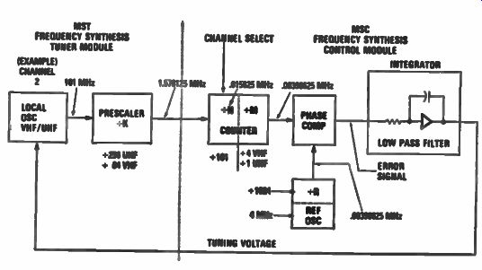
Fig. 7. Basic phase-locked loop operation.
BASIC PHASE-LOCKED LOOP OPERATION
Lets now look at a digital phase-locked loop or frequency synthesis (FS) phase-locked loop operation. See Fig. 7.
The FS tuning system for a TV receiver includes a phase-locked loop for synthesizing local VHF/UHF oscillator signals. When the RF input receives standard TV frequency carriers, the mixer combines them with local oscillator signals to form IF signals having a picture carrier equal to the nominal IF picture carrier frequency, 45.75 MHz. The PLL includes a local oscillator, a divide-by-K prescaler, a divide-by-N unit, and a divide-by-M unit, operating in conjunction with comparator, reference oscillator reference divider, and a low-pass filter.
The local oscillator, located in the MST tuner module (a voltage controlled type), generates a signal whose frequency is determined by the DC voltage applied to it from the low-pass filter located in the MSC tuner control module.
The output of the local oscillator is coupled to the divide-by-K prescaler which divides the frequency of the relatively high frequency local oscillator. This step is necessary to produce signals whose frequency is compatible with the operating frequency range of the portions of the tuning system following it. Factor K equals 256 for UHF and 64 for the VHF range.
The output of the divide-by-K prescaler is coupled to the divide-by-N unit. The divide-by-N unit performs a number of functions: One of these functions is to divide the frequency of the output signal of the K prescaler, by a number (N), which is equal to the frequency necessary to derive (in the closed loop system) the correct local oscillator signal for the desired TV channel.
The factor N is controlled in accordance with the channel selected via a channel selection unit. The channel select unit may be a keyboard type which can sequentially select the two decimal digits for the desired channel. The channel selection unit converts the selected two-digit decimal number into binary signals arranged in a binary coded decimal (BCD) format. The binary signals are partitioned into a group of four bits (binary digits) for the most significant digit (MSD) and another group of four bits for the least significant digit (LSD). The binary signals are coupled to the divide-by-N unit and are also coupled to a display unit which functions to provide an indication of the channel number selected.
A band decoder (part of the divide-by-N unit) determines the frequency band in which the selected channel resides. A band identification signal, indicating that the selected channel is in the VHF or UHF range, is coupled to the divide-by-K prescaler from the band switch stage to control the factor K (64 or 256). The output of the divide-by-N unit is coupled to a divide-by-M stage which divides the frequency of the output signal of the divide-by-N unit by 1 for UHF channels and by 4 for VHF channels, in accordance with the state of the signal coupled to it from the band decoder. The output of the divide-by-M is coupled to the phase comparator which provides an output signal comprised of a series of pulses whose polarity and duty cycle represent the phase and/or frequency deviation between the output signal of the divide-by-M divider and the output signal of the reference divider R. The output of the phase comparator is coupled to an active low-pass filter. This integrates the output signal of the phase comparator, to form a DC signal, which controls the frequency of the local oscillator.
The loop just described is arranged so that the low-pass filter couples a DC tuner control voltage to the local oscillator, which tends to minimize the frequency and phase differences between the output signals of the divide-by-M and reference divider.
AUTOMATIC OFFSET TUNING
The offset signals sometimes encountered with CATV converters, MATV systems, home video games, and video recorders fall in a range of ±2 MHz around the FCC assigned VHF broadcast channel frequencies.
These odd signals, however, must be tuned by the receiver.
The following details give the sequence of events involved with frequency synthesis automatic offset tuning. First, the desired VHF channel is selected. The synthesis system (PLL) tunes the FCC assigned frequency for that channel. When a phase lock has been completed, the system switches to an AFT mode for signal searching within the AFT pull-in range. At this time, if a station carrier frequency is within AFT range, the system stays in AFT mode and remains on channel. If a station carrier is not detected, with the oscillator tuned to this center synthesis frequency to produce 45.75 MHz, the synthesis system is again activated.
Now, however, the system automatically offsets the local oscillator plus 1 MHz above the nominal FCC frequency and the AFT search mode is reactivated. If lock occurs, the system stabilizes in AFT mode, holding the offset carrier frequency. If lock is not achieved, the system will again go to the synthesis mode, this time tuning the local oscillator to a frequency 1 MHz below the FCC nominal oscillator frequency for the channel. The AFT search is again activated, seeking a station carrier within ±1.25 MHz of this new synthesized oscillator frequency. If a carrier is available, AFT lock is established, otherwise, synthesis again retunes the oscillator to its nominal FCC channel frequency. The system will continue to perform alternate cycles of synthesis (PLL) and AFT in search of a station signal in the sequence just described.
The choice of ± 1.25 MHz for the AFT control limit prevents the possibility of AFT lockout to the lower adjacent sound carrier (- 1.5 MHz)
during dropout of the desired stations signal.
In summation:
• A channel is selected, synthesis occurs, tuning the local oscillator to the FCC nominal frequency to receive that channel.
• The AFT search mode is activated. If a station signal carrier is within ± 1.25 MHz, AFT lock-up is established and the system stabilizes in AFT mode.
• If during AFT search no carrier is available, synthesis is re-engaged shifting the local oscillator 1-MHz high; AFT search is activated, seeking a station carrier. If available, AFT lock-up is established and the system stabilizes.
• If lock-up is not achieved, the system now tunes the oscillator 1 MHz lower than nominal. AFT search is set in the same sequence as in the previous high offset mode.
• A third failure to get an AFT lock will return the system back to the FCC nominal frequency. There it will do alternate cycles of synthesis (PLL) and AFT in search of a signal, but with no further stepping. If AFT lock is established for 3 seconds, further stepping is prevented.
DC TUNING VOLTAGE AND PRESCALER FREQUENCY
A DC tuning voltage and prescaler chart for VHF low, VHF high, and UHF is shown in Fig. 8. Use this voltage chart when troubleshooting electronic tuner troubles in this system. The DC tuning voltage is connected to the MST 001 tuner module at point Pl. Tuning voltage is developed on the MSC control module, which is part of the synthesis tuning loop.
If a tuning voltage problem exists, remove power then check with an ohmmeter. Check point J1 to see if the tuning voltage is being shorted out.
If not, sub in a battery or power supply. This will serve as a tuning voltage source and will check operation of the tuner. Also, check for correct band switch voltage. Now the desired station can be tuned in by adjusting the battery or power supply to the desired tuning voltage as shown in Fig. 8.
With this set-up the prescaler frequency can now be checked with a frequency counter. If the tuner module checks out good, the problem is probably in the MSC control module.
BAND SWITCHING
Because of the limited tuning range of varactor diodes, it remains necessary to provide band-switching capability to select the low band VHF channels (2 through 6), the high band VHF channels (7 through 13) and the UHF channels (14 through 83). This is accomplished by applying +19 volts to the appropriate band-switching terminal. Refer to the band-switching chart in Fig. 9. Also included on the chart is the Mixer B+ voltage for each tuning band.
LED DISPLAY
The LED display decoder driver IC is used to drive a two-digit, seven-segment LED channel indicator. Eight lines of binary coded decimal (BCD) information are supplied to the IC located as part of the MSC control module to allow continuous, non-multiplex operation. The code which relates to the input and output states is the standard BCD-to-seven segment code which activates the appropriate segment or segments.
Figure 10 gives the logic condition or output code of the LED display driver IC. If a problem occurs resulting in loss of, or incorrect LED display, Fig. 10 will aid in determining if the problem exists in the MSC module or LED assembly.
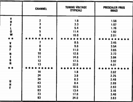
Fig. 8. Tuning voltage and prescaler frequency chart.
SERVICING THE SCAN FS CONTROL MODULE
In the following checks assume that the MST 001 tuner module and IF link cable are operating properly.
Scan Control Module Symptoms
• Channel selecting problems in either VHF low, VHF high, or UHF bands.
• Channel selecting capability lost on all channels.
• Channel selecting OK - LED display is incorrect or segments missing.
• Improper or no volume-mute.
• No tuning voltages to MST 001 tuner.
• Channel selecting OK, but tuning system hunts.
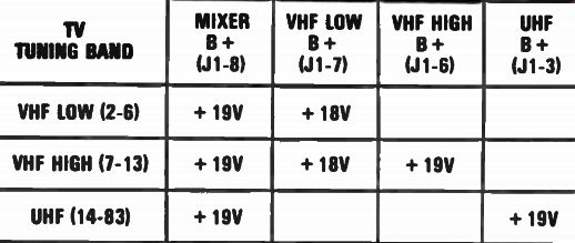
Fig. 9. Band switching chart.
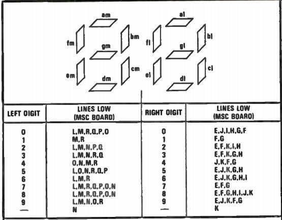
Fig. 10. LED display IC output logic condition table.
Service Procedures
Check all interface connections and wiring to and from MSC control module. Make sure that channel entered is a valid entry. Each time a channel entry is made, note the display readout This visual indication can prove to be a useful aid in tracking down a particular problem.
Channel Selecting Problems (VL, VH, or UHF Bands)
The above problems usually indicate a defect in either the MSC or MST modules. Check appropriate band-switch voltages on the MSC module. If proper band-switch voltage appears, sub in a new tuner module.
Check the proper keyboard data lines that go to logic low when buttons are depressed on the keyboard. Logic low condition means voltage goes low, to about .2 volts or lower.
Channel Selecting Capability Lost On All Channels
First check that all DC operating voltages are present. Most DC voltages for the MSC 001 are derived from the negative 60 volt horizontal pulse. These pulses are scan derived from the sweep deflection system and can be checked with an oscilloscope. Next, check keyboard data lines; if ground is not available to the keyboard assembly, channel select capability is lost.
Channel Selecting OK - LED Display Not Correct
When the tuner responds to the correct commands and the display does not, check appropriate outputs from the MSC board. Note LED display output logic condition in Fig. 10 for data regarding logic condition of display driver IC located on MSC 001 module. Replace module if incorrect logic conditions are found on the MSC module. If the correct logic conditions are found on the MSC module, then the channel display assembly may be defective.
Improper Or No Volume Mute
Check volume-mute line at J2 for a momentary "dip" toward a logic "low" condition which should exist when a channel change is initiated. If not, check plug connections and then try new MSC module. Voltage atJ2 should be about +2 volts during normal station reception.
No Tuning Voltages to MST 001 Tuner
Replace tuner control module or sub in a battery and potentiometer, or power supply in place of the tuner voltage. Remember that proper bandswitch voltage must be present to perform this test. Refer to Fig. 8 for proper tuning voltages and prescaler outputs.
Channel Selecting OK-Tuning System Hunts
This type situation usually indicates an AFT problem. Tuning capability is not lost, but picture will drop in and out rapidly, or hunt.
Check AFT voltage at J2 on the MSC module. DC voltage should measure about +6 volts and should be stable with a strong TV station tuned in.
Problem could be related to IF/AFT on main chassis or MSC control module. For other voltages and waveform information refer to the scan FS control module in Fig. 11.
ELECTRONIC TUNING SYSTEM (VARACTOR) GE ET-20 SYSTEM
Three functional blocks make up the GE ET-20 system as shown in Fig. 12. The varactor tuner is designed to tune three separate frequency bands which are activated, one at a time, by the application of +22 volts to the proper tuner terminals. These bands are as follows: Channels 2-6 54-88 MHz (low VHF) Channels 7-13 174-216 (HIGH VHF) Channels 14-83 470-890 MHz (UHF) The band switching voltage is fed by means of a wafer switch, controlled by the channel selector knob. The tuning of a specific channel within the frequency band selected is done with potentiometers in the varactor control assembly.
The varactor control assembly, shown in Fig. 13 contains not only the band-switching wafer switch, but also has twenty slide-type pots arranged on a cylinder. The wipers of each pot are mechanically engaged, one at a time, by an external tuning knob. The wipers are electrically connected to an output terminal on the assembly.
There are a different number of pots in parallel for each band. Five on the low VHF band, seven on the high VHF band, and four on each of the two UHF sections.
Each of the pots, once mechanically and electrically engaged, is capable of tuning in any channel within the selected frequency band.
The VHF channels are normally pre-tuned sequentially from the low to the high channels in order to match the numerals on the channel readout drum, and also to line up the red indicator with the white marks on the tuning dial.
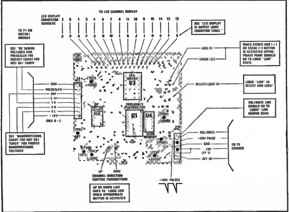
Fig. 11. Scan FS control module.
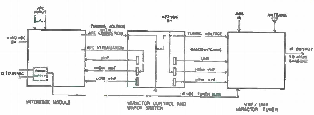
Fig. 12. Block diagram of ET-20 electronic tuning system.
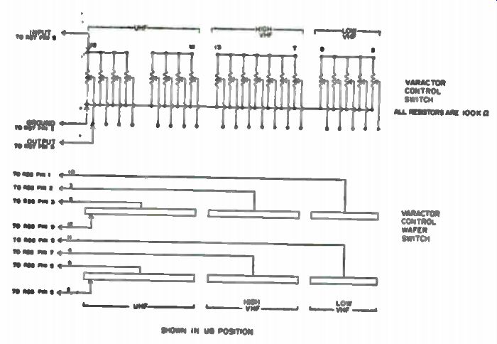
Fig. 13. Varactor control assembly diagram.
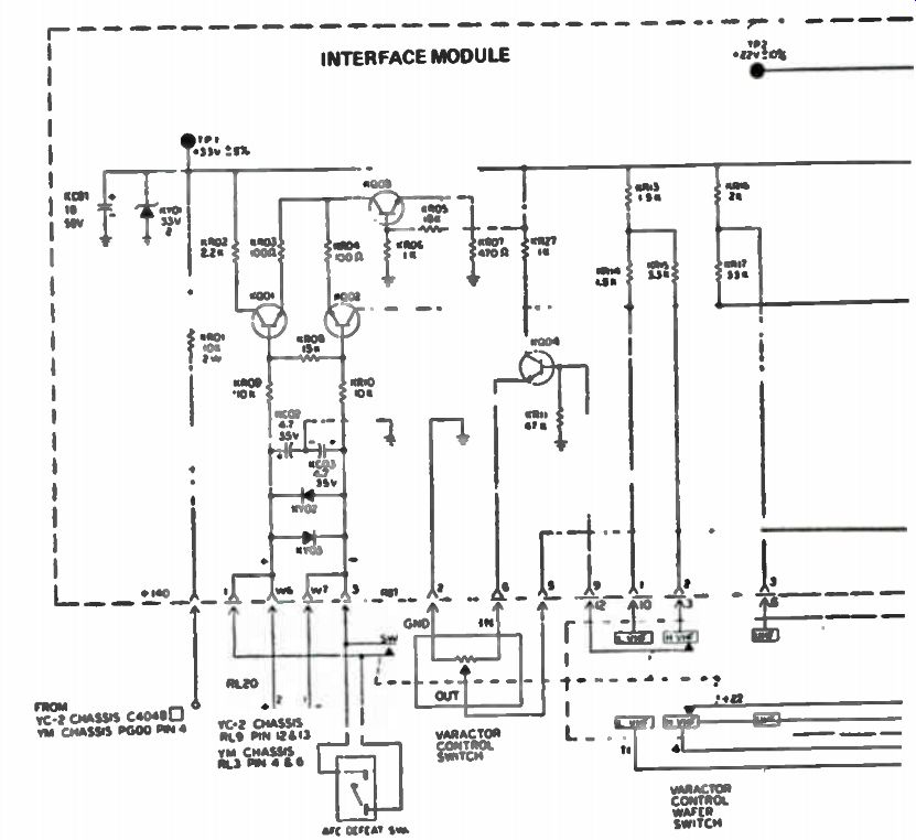
Fig. 14. Interface module diagram.
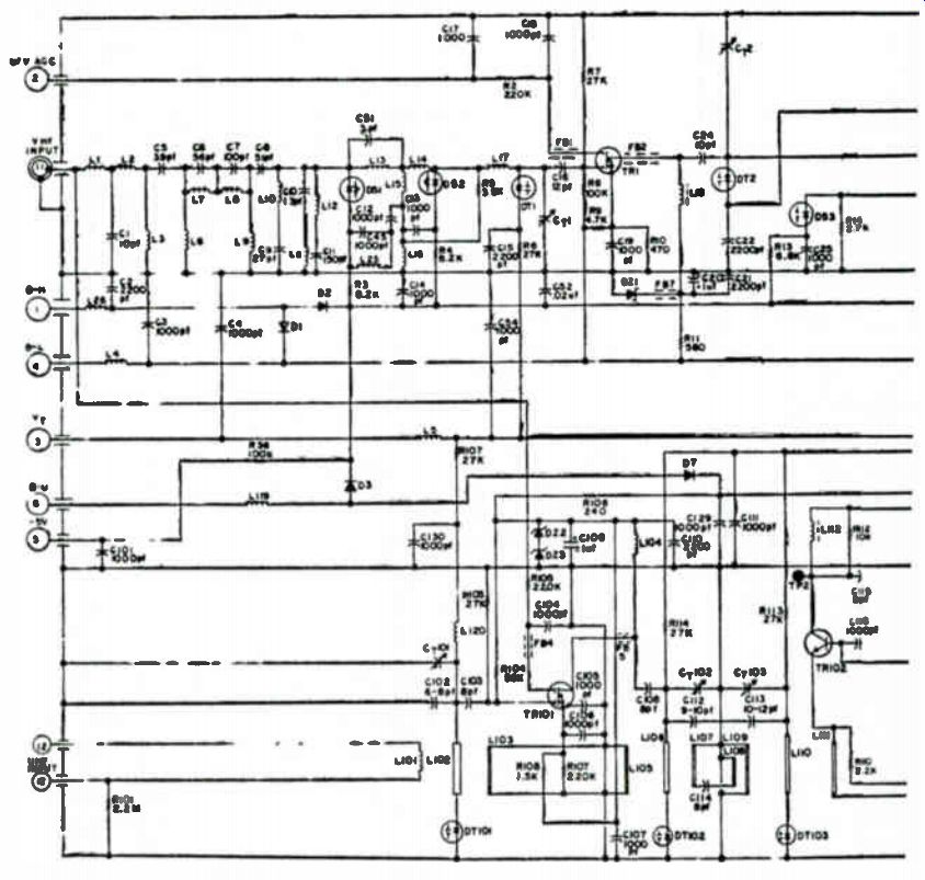
Fig. 15. GE Varactor electronic tuner circuit.
The wafer-type band-switch is mechanically connected to the potentiometer drum and, in addition to activating the proper tuner band with +22 volts DC, it also helps provide the system with the voltage needed to maintain the correct AFC range for each band. Each band requires a different amount of AFC voltage for 1 MHz of pull-in range.
The interface module shown in Fig. 14, contains the circuitry necessary to process the AFC and switching voltages required by the varactor tuner.
The AFC voltage from the main TV chassis IF module is applied to the network of KY02 and KY03. These diodes limit the differential voltage variations to 0.6 volts.
The differential amplifier stage KQ01, KQ02, and KQ03 modifies the AFC from a double ended to a single ended voltage source present at the collector of KQ02. Because of the requirement for AFC correction voltage decreases, from the low to high channels, three levels of attenuation are needed. These are provided by voltage-dividing resistors and are switched by the varactor control bandswitch to the base of KQ04. The divider network KR16 and KR17 is used for AFC level correction on the UHF band. KR13 and KR15 are used to attenuate the voltage for high VHF channels, while the collector voltage of KQ02 is used directly on the VHF low band channels.
The varactor control (tuning pots) tunes in the selected channel frequency by setting the voltage level required at terminal 3 of the varactor tuner via the buffer stage KQ05. The tuning voltage is altered by KQ04 in direct proportion to the AFC correction voltage present at its base.
A bias voltage which can vary from - 5 to -8 volts DC is applied to terminal 5 of the varactor tuner. This voltage is developed by KY06 and its associated circuitry. The bias prevents the tuner from producing unwanted oscillations under certain conditions. The complete circuit for the VHF - UHF Varactor tuner is shown in Fig. 15.