AMAZON multi-meters discounts AMAZON oscilloscope discounts
Oscillators play two major roles in communications. In the receiver, a low-power oscillator is necessary for superheterodyne operation; and in the transmitter, the oscillator is the basic signal source.
In a receiver a single stage often is a converter. This stage has the RF signal as an input. Since the same stage acts as an oscillator, its own signal is the second input. Usually this signal is higher in frequency than the RF. However, in receivers covering a band of frequencies, it is possible to reduce bandswitching by operating on the low side of the RF for part of the band and on the high side for the remainder of the band.
Either a separate oscillator stage can be used ( as with communications receivers and some auto radios), or a single stage can be employed as a converter. The latter is found in most portable transistor radios.
For transmitters, or in some controls which require a stable signal source, crystal-controlled oscillators are needed. With the rapid advance of transistor technology, oscillators are now avail able from audio frequencies to well into the UHF region.
Hartley, Colpitts, and other familiar oscillators are all used.
But since transistors are current-operated devices ( unlike tubes, which are voltage-operated), special considerations are necessary. The tube plate, grid, and cathode resemble the transistor collector, base, and emitter in some of their actions. Transistors in oscillator circuits use both NPN and PNP configurations. NPN transistors in a grounded-base arrangement have a negative voltage applied to the emitter and a positive voltage to the col lector. In the PNP these voltages ( or more accurately, current sources) are of opposite polarity. A grounded-grid tube cor responds to the grounded base, a grounded cathode to a grounded emitter, and a grounded plate to a grounded collector.
(A) 50 -mhz oscillator.
1-SMMF 3/4" DIA. COILS
(B) 200 -mhz oscillator.
------------183 Self-excited high-frequency oscillators.
SELF-EXCITED HIGH-FREQUENCY OSCILLATORS
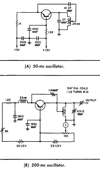
Two high-frequency oscillators are illustrated in this circuit.
Part A shows a 50 -mhz oscillator designed to use a surface-barrier transistor ( SBT). Suggested types are a 2N 17 44, 2N502A, 2N1270, and 2N776. The feedback capacitor from the emitter to the coil tap is about 27 mmf, but its value depends on the transistor used.
Part B illustrates a 200 -mhz oscillator circuit designed for use with a micro-alloy diffused-base transistor ( MADT). Suggested types are 2N1744 and 2N502A. Here a variable capacitor is used for the feedback. This capacitor, plus the 10K control, are adjusted for maximum output within the ratings of the transistor.
TUNNEL-DIODE CRYSTAL OSCILLATOR
Part A of the diagram shows a tunnel diode used as an amplifier in a typical low-frequency circuit. If the incoming signal is a sine wave, its positive half-cycle will add to and thus aid the battery voltage. Hence, the diode current will drop and so will the IR drop across output resistor R1.
In this way, a positive-going input signal produces an amplified negative-going output signal. This amplified signal can be used with an oscillator. Part B shows a crystal-oscillator circuit at 27.8 me. A 1N2929 is used as the oscillator, and bias stabilization is provided by backward diode HU-100.

-------------- (A) Amplifier. (B) Tunnel-diode oscillator.
Tunnel-diode crystal oscillator.
--------------- Four-layer diode RC oscillator. (A) Astable circuit. (B)
Monostable circuit. (C) Bistable circuit.
FOUR-LAYER DIODE R-C OSCILLATOR
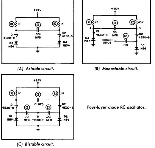
The four-layer diode can also be used for free-running or bi stable circuits. Part A shows a free-running multivibrator that uses a four-layer diode. If diode 4D1 has just turned on, point A will be at ground potential as long as the current passed by resistor R1 is greater than the holding current of 4D1. As capacitor C1 charges through resistor R2, the voltage at point B will in crease to the switching voltage of diode 4D2.
At this time 4D2 will switch on, and point B will suddenly drop to zero. At the instant of switching, there is a negative-to-positive potential across capacitor C, between points A and B. Therefore, as point B drops to zero, point A is driven negative before C1 has a chance to discharge. This reverse bias turns diode 4D 1 off, and 4D2 now carries the load current through R2. Capacitor C1 then charges in the opposite direction, through resistor R1, until point A reaches the switching voltage of diode 4D 1. As this occurs, diode 4D1 switches on, the voltage across C1 turns 4D2 off, and load current once more flows through R1.
Part B shows the monostable, or one-shot, configuration. Here the circuit is such that when one leg is on, the other is off. This is accomplished by choosing 4D1 to have a lower switching than supply voltage, and 4D2 a higher switching than supply voltage.
A negative-going trigger pulse through capacitor C2 switches 4D2 on. This in turn switches 4D1 off through the coupling action of Cl. R2 will pass current to 4D2; if this current is higher than the holding current of 4D2, this diode will remain on until capacitor C1 has charged, through resistor R1, to the switching potential of 4D1. At that time, the circuit will revert to its initial stable condition with 4D1 on.
In this operating mode, the time constant R1- C1, and the ratio between the supply voltage and switching voltage of 4D1, both determine how long leg B will stay on.
Part C shows the bistable multivibrator circuit. This circuit is switched from A to B, and back to A, by successive negative trigger pulses inserted via C2 and C3. The four-layer diodes 4D1 and 4D2 are chosen to have higher switching than supply voltages. R1 and R2 are small enough in value to provide holding currents for diodes 4D1 and 4D2, respectively. Diodes D1 and D2 provide high impedances across which the negative trigger pulses are applied. Their forward-current ratings must be adequate for the load currents determined by R1 and R2. C1 must be large enough to insure positive switching, so that both sides are never on simultaneously.
MADT BLOCKING AND CRYSTAL OSCILLATORS
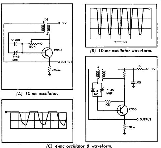
The microalloy diffused-base transistor has characteristics which make it useful as a high-speed blocking oscillator. Part A of the diagram shows a 10-megacycle free-running blocking oscillator. The output pulse has a width of 28 milli-microseconds, as shown in Part B. In Part C the 4 -mhz crystal-controlled blocking oscillator does not show any apparent drift in frequency up to 65°C., even though the supply voltage has been varied from -2.5 to -9 volts.
The variable capacitor in either circuit can be adjusted to compensate for slight variations in pulse width, such as will occur when different transistors are used in the circuit. These circuits can be triggered at their bases when the base-to-collector resistor is eliminated.
--------------- MADT blocking and crystal oscillators.
(A) 10-mhz oscillator. (B) 10-mhz oscillator waveform. (C) 4-mhz oscillator & waveform.
TUNNEL DIODES AS SINE-WAVE OSCILLATORS
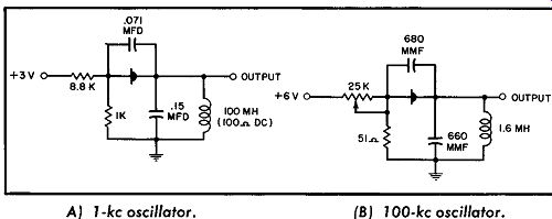
A backward diode can usually be used as a low-current tunnel diode. The ZJ69 is shown here in two circuits. Depicted in Part A is a 1 -khz sine-wave oscillator with 1-microwatt output using a +3-volt supply.
Part B shows a circuit similar to the one in A, but for a 100 -khz output.
----------------( A) 1 -khz oscillator. (B) 100 -khz oscillator. Tunnel diodes
as sine-wave oscillators.
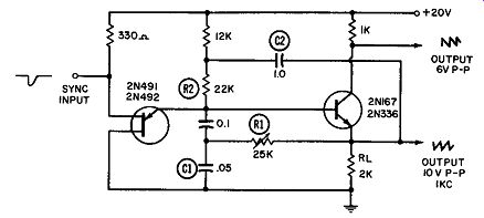
----------------- Sawtooth-wave generator.
SAWTOOTH-WAVE GENERATOR
In this unijunction generator, NPN transistor X is in a state of conduction while unijunction ( UJT) is normally cut off. When a negative-going sync pulse is applied to the base of the UJT, the cutoff bias is overcome and the UJT conducts from +20 volts, through the 12K and 22K resistors, to ground via the UJT. Because of the UJT conduction, the increased IR drop across the 12K and 22K resistors will cut off transistor X at its base. X's voltage-going positive at the collector and negative at the emitter-is taken off at points A and B, as represented by the waveforms. Outputs A and B are 6 and 10 volts peak-to-peak, respectively, in a frequency range of 350 to 600 hz.
TUNNEL-DIODE SQUARE-WAVE OSCILLATOR
In this square-wave oscillator, capacitor C charges through R1 and R1 until the tunnel diode reaches its peak current and switches. The base current of the transistor then causes the transistor to go into saturation, shorting the collector and point B to ground. The capacitor then discharges through R1 and R2 until the voltage at point A falls below the cutoff of the tunnel diode. The diode will then return to the low-voltage state and turn the transistor off. The cycle is then repeated.
The symmetry of the output can be changed by feeding a small current into or taking it out of point A. The period of oscillation is about 300 microseconds.
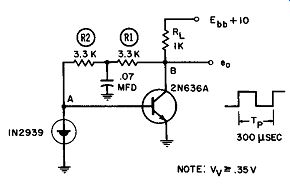
-------------- Tunnel-diode square-wave oscillator.
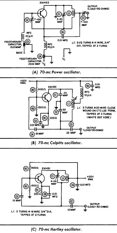
--------------- Self-excited 70 -mhz oscillators.
(A) 70-mhz Power oscillator. (B) 70-mhz Colpitts oscillator. (C) 70-mhz Hartley oscillator.
SELF-EXCITED 70-mhz OSCILLATORS
Three self-excited oscillators that use NPN silicon transistors (2N1491, 2N1492, and 2N1493) are shown here. At 70 mhz the 2N1491 has a maximum collector-to-base rating of 30 volts and can deliver 70 milliwatts, the 2N1492 has a voltage rating of 60 volts and can deliver 100 milliwatts, and the 2N1493 has a 100 volt rating and can deliver 500 milliwatts.
Although the 2N1491 is shown in two circuits, either the 2N1492 or the 2N1493 can be used, with the proper collector voltage, to provide a higher power output. In Part A, an output of 1.25 watts is obtained when a typical 2N1493 is used at a collector voltage of 50 volts and a collector current of 25 milliamperes.
The transistor case should be clamped firmly to the copper chassis. This provides a low thermal-resistance path for heat dissipation. No insulating mica spacers are required, since the collector is also connected to chassis ground.
Low-power VHF oscillators are required in many applications, including local and variable-frequency oscillators in transmitters.
An output power of about 25 or 50 milliwatts usually is sufficient.
The Colpitts oscillator shown in Part B of the diagram has a maximum output of up to 50 milliwatts and a typical value of 35 milliwatts. The Hartley oscillator in Part C has approximately the same output capabilities. The 2N1492 or 2N1493 may also be used in these circuits if a higher power output is required.
CODE-PRACTICE OSCILLATOR
Shown here is a single-transistor audio oscillator that can be used for code practice. The circuit has sufficient output ( 300 mw) to drive a small speaker. A control is provided for varying the frequency (tone). If desired, a volume control may be added, in the form of an L-pad in the speaker voice-coil lead.
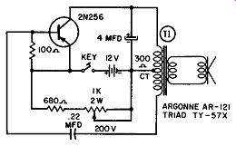
------------- Code-practice oscillator.
100-khz CRYSTAL OSCILLATOR
This circuit is a 100-khz crystal oscillator using a 2Nl613 transistor. The oscillator has both a square- and a sine-wave output. Its frequency stability is excellent ( 3 ppm over a transistor-case temperature range of -55° to + 125°C.). In fact, the oscillator is suitable for use as a secondary frequency standard.
The circuit operates like a Hartley oscillator. Positive feedback from collector to base is obtained by using the phase reversal of tapped tank circuit L2, L3, and C2. Oscillator frequency is determined by the resonant frequency of the very high-Q series LC network in the feedback loop. This network is made up of capacitor C3 and a quartz crystal which appears inductive at 100 khz.
Feedback, which drives the collector between cutoff and saturation, is responsible for the square-wave output. L1 and C1 develop the sine-wave output.
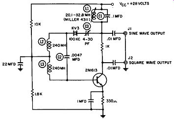
------------ 100-khz oscillator.
250-mhz OSCILLATOR
The 2Nl491-2Nl493 transistor series can be used for high-frequency oscillators. This figure shows a 250 -mhz oscillator circuit using a typical 2N1493. Here an output of 150 milliwatts at 250 me-with an efficiency of 15% to 20%-is obtained.
The output-matching pi circuit reduces the harmonics in the load. As in all other high-frequency circuits, the leads must be kept short to minimize stray capacitance .
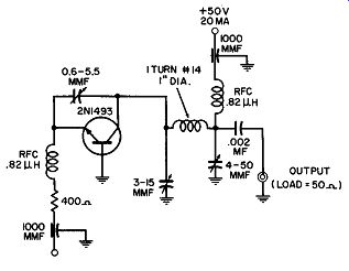
-------------------250 -mhz oscillator.
BLOCKING OSCILLATOR
A blocking oscillator using the 2N697 silicon transistor is shown here. This 108.5-khz circuit is triggered by a sine wave at this frequency. The first stage, which is used as a grounded emitter, is overdriven by the input sine wave to provide a trigger pulse for the following oscillator stage.
The three-winding transformer uses a square-loop core of molybdenum-permalloy. The 20-turn winding has a normal cur rent How from the 25-volt source in series with 1,800 ohms.
A positive base trigger starts the collector current through the largest ( 30-turn) winding. This current How is in a direction which tends to switch the transformer core to the opposite state.
As switching begins, the voltage developed across the eight-turn winding drives the emitter negative and keeps the transistor con ducting until core saturation occurs.
At saturation, the core voltage drops sharply to zero because of its square-loop characteristic. Without the negative emitter voltage, the transistor turns off and the core is reset. The normal state, to which the transistor returns because of the bias current, is the set state. The emitter capacitor shown speeds the transistor on-and-off action.
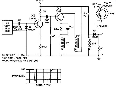
------------ Blocking oscillator.