Apart from the service uses of the VOM in radio, TV and hi-fi, there are many others for which it is handy, and some for which it is indispensable. Necessarily these cover many items in areas where we would not normally think of the VOM as a fitting tool. You will undoubtedly think of still others as you become more familiar and accustomed to working with the VOM.
Some measurements we have described can be made in a more sophisticated manner, and there will be a few sections on these.
And, although serious repair of the basic instrument in the VOM should be done by a competent instrument repair service, you can do a number of things to keep yours in good shape, and these will be listed.
Measuring L and C
In an earlier section we discussed the measurement of inductance and capacitance by methods which compared the unknown with a standard resistor at a particular frequency, or with another inductor or capacitor. These are reasonably accurate methods, but they are not always easy to do for small values of inductance and capacitance, where higher frequencies must be used. Also, we can't always be sure that the meter does not contribute to the circuit values in some way. To get around this, we can try another method which hinges on the fact that, for a particular frequency, there will be only one capacitance which resonates with a given inductance, and vice versa.
Either series or parallel resonance can be used. In a series arrangement, the total impedance of the circuit will be the least at resonance, while in a parallel circuit it will be highest. If we wish to learn the inductance of a certain coil and we have a capacitor (whose value we know) available in approximately the right range, then by varying the frequency and tuning for resonance, we can discover the resonant frequency, and from this calculate the unknown.
This method depends on several factors. First of all, you must have a good resonance indicator. The VOM in combination with a small capacitor and a diode will serve for that; but you must also know the exact frequency used, and for this you will be de pendent on the accuracy of a signal generator. Fortunately, there are many ways to calibrate a signal generator; for example, by using a receiver and tuning it to a broadcast station and then tuning the signal generator until it produces its modulated tone on top of the station, and other such easy methods.
Measuring inductance by the parallel resonance method
Fig. 1001 shows the principle used for measuring an unknown inductance with a known capacitance by the resonance method.
What we have here is a parallel resonant circuit with the signal generator tuned for the highest indication on the meter.
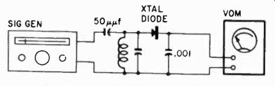
Fig. 1001. Measuring inductance or capacitance with the VOM, using the principle
of parallel resonance. The VOM should be set on its lowest dc voltage range.
Set the signal generator attenuator for maximum signal output.
The crystal diode will rectify the voltage developed across the parallel circuit, consequently we will want to set our VOM to read dc volts. The .001-pf capacitor is an rf bypass, so that the voltage reaching the VOM will be dc essentially.
You may run into some difficulties when trying this arrangement on the higher frequency ranges of the signal generator. Many generators use harmonics of the lower frequencies to get to the upper ranges. This technique is a good one but it does mean that the rf output of the generator is much weaker at higher frequencies. Whenever possible, use the lower scales of the signal generator. A coil and capacitor combination will resonate at many different frequencies, depending on the setting of the capacitor (if variable) and the positioning of the coil slug (if it has one).
A safe procedure is to try to have the variable capacitor as completely meshed as possible (giving maximum capacitance) and the tuning slug of the coil turned in. The best position for the slug is so that it is at the center of the coil. This is the maximum inductance position. Turning the slug so that it is all the way inside the coil form is no assurance that it is in the correct position.
Doing this sometimes pushes the slug out of the coil, thus lowering the inductance.
When running this test, try to use a sensitive VOM. One of the devices described earlier to increase the sensitivity of the instrument would be helpful. Also, be sure to set the attenuator of the generator for maximum output.
Measuring inductance by the series resonance method
In Fig. 1002 the same measurement is made with a series circuit, but notice that the diode now is in series with the circuit elements, and again you tune for maximum deflection on the meter.
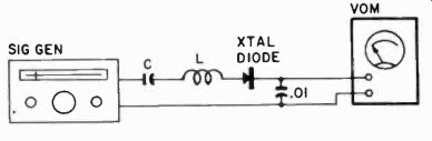
Fig. 1002. Using the vom and series resonance to measure inductance or capacitance.
The signal generator should be set for maximum output; the VOM on its lowest
dc voltage range.
When you know the frequency, you need two formulas, one for the inductive reactance and one for the capacitive reactance:
1 XI, = 2 pi lL and X, 2 pi fC
At resonance these two values will always be equal, and thus we can get L and C on one side of the equation:
1 LXC'- (274)2
So for any frequency that you read on the signal generator dial, you can calculate the product of L and C, and then simply divide by the known value, whatever that is.
A "capacitor or inductance of about the right value" means one which would have approximately the same magnitude of reactance at some reasonable frequency where it might be used. Thus, if you made the capacitance large enough, you could probably measure the inductance of a broadcast frequency coil at audio frequencies, but your method would be so lopsided that you would not get an accurate measurement. If, instead, you measured it at broadcast frequencies or thereabouts with a capacitor of about 500 uuf, you would get a rather good measurement.
Using a nomogram
Since this combination of inductance and capacitance is very common in electronics, we usually can find a nomogram that takes all the work out of the calculation. See Fig. 1003 on the facing page.
To determine a resonant frequency construct a straight line between the left-side values of L and C. Read the resonant frequency on the left side of the f scale. For a more exact solution construct a second straight line between the right side of the L and C values, using the significant figures of L and C. Read the significant resonant-frequency figures on the right side of f. Decimal location is in accordance with the left-side solution. To convert from frequency to wavelength construct a horizontal straight line through the value of frequency on the left-side f scale. Read wave length on the left A scale. Similarly construct a second horizontal straight line through the value of frequency on the right side of the f scale. Read significant figures on the right A scale. The horizontal condition can be observed in both cases by equal intercepts on the L and C scales.
As an example, find the resonant frequency and wavelength of a circuit containing 1-mh inductance and .002-uuf capacitance.
Construct a straight line from 1 mh on the left side of the L scale to .002 uuf on the left side of the c scale. This will give us about 100 megacycles at the intersection of this line with the left side of the f scale. At this intersection construct a horizontal line. Estimate 3 meters on the left A scale.
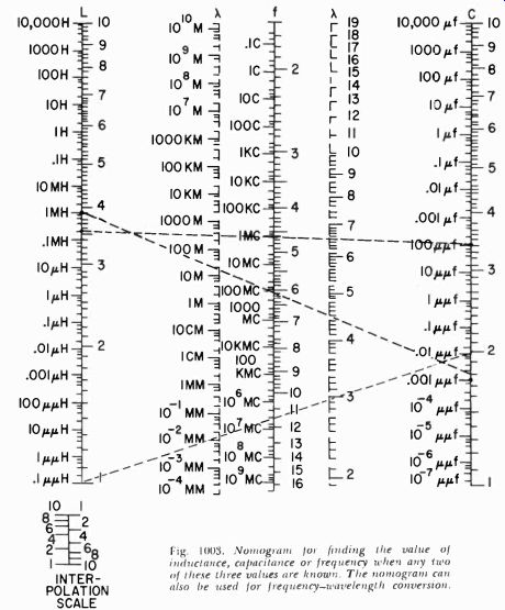
Fig. 1003. Nomogram for finding the value of inductance, capacitance or frequency
when any two of these three values are known. The nomogram can also be used
for frequency-wavelength conversion.
For a more exact solution construct a straight line from the bottom 1 on the right side of the L scale to 2 on the right side of the C scale. Read about 112 mhz on the right side of the f scale.
(For more exact reading use interpolation scale insert.) Construct a horizontal line through this intersection and read 2.67 meters on the right A scale. Using the top 1 on the right side of the L scale would obviously be wrong since it would be incompatible with the first solution.
What we have said so far will give you an indication of how the chart works. If we have three unknown factors, and know any two of them, we can always find the third. Thus, knowing the values of inductance and capacitance, we can easily determine the frequency at which this combination will resonate. But if we know the frequency (our signal generator tells us that) and we know the value of inductance we are using, we can get the value of capacitance from the chart in Fig. 1003. Similarly, if we know the frequency and the value of capacitance, the chart will give us the value of inductance.
As an example, let us say that you have a 100 uuf trimmer and that our VOM gives us a peak reading when we set the dial of the generator to 1 mc. On the chart we connect these two points with a straight line and on the left side of the L scale we can read the values of inductance as approximately 0.2 mh.
In Figs. 1001 and 1002, the circuits have been shown connected directly to the generator. This is not a necessity. If you use a grid-dip oscillator, in which the coil is exposed, you need only bring the parallel resonant circuit near the coil to get an indication.
Using the capacitance scales to measure inductance
Some VOM's come equipped with capacitance scales. With a little arithmetic these can he used to measure the inductance of coils having a low resistance. Using the ohmmeter section of the VOM, measure the resistance of the coil. Make a note of the reading.
Do not disconnect your test leads, but switch the selector on the VOM so that it is set to read capacitance in microfarads. The inductance of the coil can now be found by using this equation:
VX2 R2 377
In this case, X is the capacitive reactance at the line frequency which we are assuming to be 60 cycles. We get the number 377 in the denominator of the equation by multiplying 60 X 27.
To see how we use this method, let us suppose you have an un marked choke coil. You measure its resistance and find it to be 30 ohms. When you check the choke using the capacitance scales of the VOM, you find that you get a reading of 10 pf. To find the capacitive reactance of a 10 pf capacitor at 60 cycles use a capacitive reactance chart such as the one shown on page 118. This is a handy thing to have. If not, then calculate the reactance using this old standby:
L 1 27rfc In this case the reactance comes out to be 265 ohms. This is X in our equation.
Xe =
V2652- 302 L 377
-0 7 henry
Keep in mind, though, that this is the maximum inductance of our choke. The inductance will be affected by the amount of dc flowing through the coil.
If, in measuring the resistance of the coil you find that it is very small compared to its inductive reactance, then you can ignore the resistance. You can do this if the inductive reactance is about ten times as much as the resistance. In such cases the formula for inductance simplifies to:
L 377
Phase-angle determination
Determining phase angle is a little trickier than some of the measurements described, but it is entirely feasible with a VOM, provided you understand what is happening in the circuit.
Because it takes time to charge a capacitor, the current in a circuit containing capacitance will show the greatest change when the voltage across the capacitor is still low. This means that, at any time, the current may have reached a maximum value well before the voltage comes up to its maximum value. In other words, the current "leads" the voltage in a capacitive circuit. We represent this by vectors, which are simply arrows drawn for convenience in calculations, and we usually draw them through an origin about which they can rotate.
In an inductance, the opposite happens. When we apply a voltage to a coil the magnetic field created causes a counter-emf to be generated which delays the current from reaching its maximum value as fast as the voltage. We say that the current "lags" behind the voltage or that the voltage leads the current.
This phase angle (amount of lag or lead) between current and voltage cannot be measured directly, but we can measure values which will allow us to construct the phase angle graphically by means of vectors in some cases.
Consider, for example, the circuit in Fig. 1004. Here we show a transformer with a split secondary, and a capacitor across one half of this secondary. We know that this capacitor will change the phase angle of the voltage in that half. But how much? Normally the voltages in the two halves of such a split winding will be equal and opposite in phase, which in terms of vectors would be two arrows of equal length and in opposite directions (Fig. 1005-a). But if we add the capacitance shown, one of the vectors rotates just a little, as in Fig. 1005-b. Now if we were to measure the voltage across each half (ignoring the possibility of resonance), we would measure the same voltage in both halves.
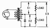
Fig. 1004. Because of the presence of the E3 capacitor, the voltages across
the two halves of the secondary winding will no longer be exactly 180° out
of phase.
But, if we measure the two together (E3 in Fig. 1004) , we find that the two don't add up to the arithmetic sum of E1 and E2. This is due to phase shift.
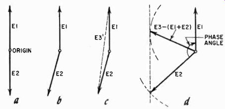
Fig. 1005. Vector relationships of the circuit of Fig. 1001. Without the capacitor
(a) the vectors are 180° out of phase. The capacitor shifts the phase of the
voltage (b). The vectors can be added algebraically (c). Method of finding
the phase angle (d).
In Fig. 1005-c we show how such values would add up as vectors.
What you would actually measure for E2 is E3'. If we can measure E1, E2 and E5, we can find the phase angle as shown in Fig. 1005-d.
First, put down a value E1 represented by a certain length, say 1/4 inch per volt. Now take a compass and set it for the difference between ES and the sum of E1 and E2, ES = (E1 E2) and draw the arc shown. Next, just barely touching the arc draw a line parallel to the line representing E1 and tangent to the circle we have drawn. Now set your compass for the value of E2 in the same units, and draw an arc from the same origin as before. Where this second arc crosses the line parallel to E1, draw E2. Then with a protractor (or with trigonometry if you are skilled in this), you can measure the phase angle between the two voltages. Notice that the voltages E1 and E2 do not necessarily have to be equal for you to use this procedure. So long as you represent each value as a vector in the same kind of units, whether this is 1 inch or 1/2 inch per volt or what have you, you will end up with the true vectors representing the phase angle between the two. You will not be able to tell which leads which unless you look at the circuit and remember that a voltage in a circuit with capacitance is naturally "behind" one which has inductance only.
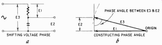
Fig. 1006. capacitors are often used to shift the phase of a voltage (a).
The angle (b) indicates the amount by which the phase has been shifted.
In industrial electronic circuits capacitors are often used to get a phase shift for reasons of control. In the circuit of Fig. 1006--a we show a capacitor and resistor in series. Our "phase-shifted" voltage would be taken off between the two; in other words, E2. To know just how much we are shifting phase, we again make the same three measurements, and draw the two vectors as shown in Fig. 1006-h. Start with E1 and then draw an arc with the compass set at the value for E3. Where this intersects the vertical line drawn at the end of E1, you can measure the value of E2 to check and then draw in E3. Now the angle indicated is the angle of phase shift accomplished with the capacitor.
We could go on and further complicate matters by using an inductance and a capacitor. However, we are still talking about the VOM, and the only other thing we will say about vector diagrams is that in resonance the two vectors of capacitance and inductance will be exactly opposite, exactly 180° out of phase.
Time measurements with the VOM
If we use a circuit such as shown in Fig. 1007 and charge a capacitor through a resistor, the voltage across the capacitor will rise gradually if both the capacitor and the resistor have high enough values. It can take a number of seconds for the voltage to reach a stable point. However, this point will depend on the relationship between the input resistance of the VOM and the charging resistor, for, as shown, the capacitor will ultimately receive a voltage which is a proportion of the total resistance.
Fig. 1007. The voltage across C will rise slowly, giving E as a measure of time.
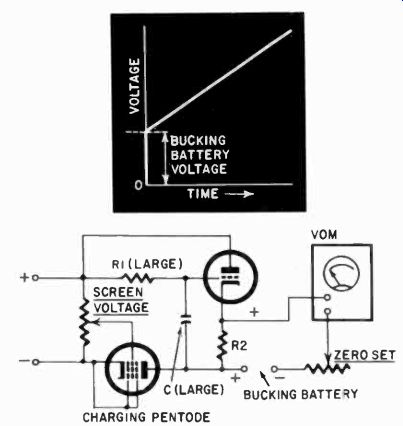
Fig. 1008. Linear tune measurement, using the VOM.
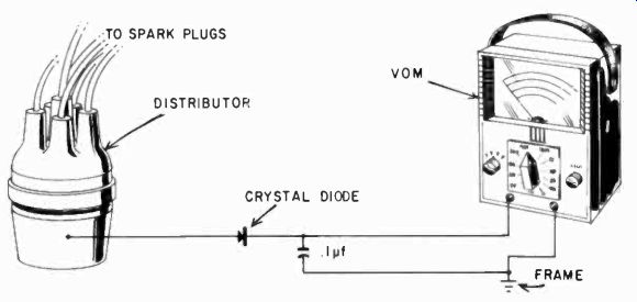
Fig. 1009. The VOM can be adapted for use as a temporary tachometer.
Unfortunately this type of circuit does not charge linearly, but according to the well-known capacitor charging curve. The time units would have to be calibrated because, on the low part of the scale the voltage time units would be large and at the top they would be small. But with a simple additional circuit we can make this curve almost perfectly linear, and this is shown in Fig. 1008. Here a pentode is used to charge the capacitor. This assures constant current in the circuit, while the cathode follower prevents the VOM from discharging the capacitor. Using a cathode follower, we would find an initial voltage on the cathode, but this can be bucked out as shown. No values are indicated in the circuit because they depend to a great extent on tube characteristics. However, the order of resistances is also dependent on time and the size of the capacitor. For several seconds' rise, if C is about 4 pf, then R1 should be approximately 5 megohms and R2 approximately 47,000 ohms. But these values may be changed to suit the individual tubes, available voltages and the size of the capacitor in the circuit.
The VOM in the garage
There are a number of uses for the VOM in the garage. First, there is the check on the condition of the auto battery, which we discussed before. Then there are such self-evident applications as a check of wiring insulation, continuity checks, etc.
The VOM can also make a fine temporary tachometer, useful for adjustments that have to be checked several times at different rpm's-carburetor adjustments, for example. The circuit is shown in Fig. 1009. The pulses are obtained from the low-voltage contacts of the distributor and integrated in the .1 pf capacitor. With a 6-volt system, a reasonable deflection can be expected on the 25- or 30-volt scale on a 20,000-ohms-per-volt meter. The voltage is proportional to the number of pulses; in other words, the rpm's of the motor, the voltage of the battery and the dwell time of the contacts. The VOM must be calibrated with a mechanical tacho meter, but for a single car the calibration holds quite well if the breaker dwell timing is not changed. And a mechanical tachometer needs to be held against the rotating shaft or some such part, while an electronic one leaves both hands free for other work.
A somewhat better tachometer is shown in Fig. 1010. The circuit is essentially the same, but here a microswitch is used in stead of the distributor breaker. The microswitch is set up so that a small piece of tape stuck to the flywheel ova pulley lifts the arm once per revolution. If you always use tape having the same width, you need not worry about dwell time, and the device can be calibrated. The microswitch should be a rather rugged type with a roller, for this is heavy-duty operation for such a switch. Do not keep it on the flywheel any longer than necessary. One such separate switch worked quite successfully when attached to a bracket which was held in place in the automobile by a strong Alnico magnet.
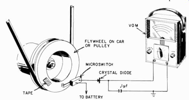
Fig. 1010. This temporary tachometer is independent of dwell time.
Checking distributor timing
The VOM can also be used to set the distributor timing. All cars have a timing mark somewhere on the flywheel, the driving pulley for the fan or on the ring gear. When this mark is lined up with a mark on the frame, the breaker contacts are just opened, firing the plugs. If you connect the VOM as shown in Fig. 1011, you can readily tell when the breaker contacts open, and adjust the position of the distributor to make this point come at the right moment. Usually this must be set for a specific cylinder, generally the first mentioned in the firing order. For this you can refer either to numbers stamped on the engine block or to the manual, if any, which comes with the car. Timing is changed by the position of the distributor and dwell time by the opening of the breaker contacts. The sooner the contacts open and the more Fig. 1011. Setting distributor timing with the VOM, they open, the smaller the dwell time. The spark discharge will have more energy when the dwell time is greater. In this operation the car can be cranked by the starter if you pull the center high-voltage lead off the coil so the plugs won't fire and the engine start up while you're working on it. Ignition must be on: otherwise there would be no voltage at the distributor.
Regulator adjustment
Another check point in an automobile where the VOM can be used is the regulator adjustment and the generator current. Many late-model cars no longer have an ammeter, only a red light to show when the generator is not charging the battery, but you will never know from that how much the generator is charging. For that you'll have to check its output at different rpm's. This is simply a current measurement, but you'll need to have a 20-ampere (or higher) range for the meter. Earlier we showed how to make shunts to extend the meter to higher current ranges.
Associated with the generator is the regulator, which does not allow the battery to be connected to the generator until the latter produces enough voltage to be certain of a charging current to the battery. This is a differential device, checking the generator voltage against the battery voltage and, if the former is enough higher, contacts close and lock in. The differential should be quite small. At a speed of 2,500 rpm (generator speed), the generator should put out enough voltage (about 7 to 7.5 volts) to cause the regulator to close its contacts. If it does not, the contacts may be stuck. When the generator voltage drops below 6.3, the regulator should open. Regulators on most cars control the current as well as the voltage at which the contacts close and some are quite tricky to adjust, if adjustable at all; but at least you can quickly locate the source of trouble if your battery is not being charged.
The VOM in the laboratory
Fig. 1012. Simple humidity meter using the vom. Start with salt which has been heated to remove any traces of moisture. You will need to experiment with the spacing between the electrodes, as well as with the correct resistance range to use.
Depending on what kind of laboratory you may be working in, the VOM can be a handy instrument for many purposes. For example, in many lab measurements the relative humidity is an important parameter of whatever experiment is going on. A humidity measurement can be made with the simple arrangement shown in Figs. 1012 and 1013. The lid, which acts as one electrode, is filled with ordinary kitchen salt to cover the little screen or grid which forms the other electrode. Naturally, the screen and the lid of the jam jar are insulated from each other. The resistance between the two is a measure of the amount of moisture absorbed by the salt from the air.
This kind of humidity meter has one disadvantage: the salt will eventually saturate, and then must be heated to return it to normal. If you can set the apparatus up so you can place a small flame under it when you feel the salt needs to be dried out, this is one way of restoring the humidity meter. If not, simply dump the salt and start over.
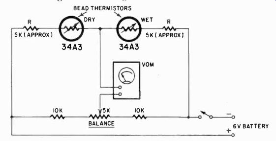
Fig. 1013. This is a more precise humidity meter. The two resistors (R) must
be selected to obtain a reasonable balance. The "wet" thermistor
should be covered with a wick which sits in a glass of water.
A better and more stable humidity meter is shown in Fig. 1013.
Here the sensitive elements are two thermistors, one in the air and the other inside a wick which soaks up water from a glass.
Because of the greater cooling of the wet thermistor due to small air currents and evaporation of the moisture in the wick, the two thermistors and the VOM will indicate what is, in effect, a temperature difference, but one which is related to the moisture of the "dry" thermistor. Thus the "wetter" this one is, the less difference in the temperature and the greater the humidity. Zero set is adjusted when the wet bulb thermistor is out of the water and its wick dry. Notice that this is a bridge-type circuit. with approximately equal resistance in the legs, so that any tempera ture effects on these resistors is mostly compensated for. The relationship between wet and dry temperature difference and humidity can be obtained from tables in physics handbooks and air conditioning texts.
Measuring the concentration of a solution
Every solution and suspension of matter in a liquid has its own characteristic conductivity, and from measurements made with a pair of inert electrodes you can pretty accurately deter mine the concentration of a solution, if you know what the values should be. There are charts in chemical handbooks which tell you what they must be. The setup is simple: the two electrodes can be platinum wire or some other noble metal (separated by a plastic spacer) at a fixed distance from each other and always submerged exactly to the same depth. The resistance measured this way with the VOM is your indication of the concentration of the solution, and can also be an index of its purity. For example, drinking water is tested this way for possible solids suspended in it and salts dissolved in it; boiler water is checked for "salinity" in the same way.
The same electrodes, if you are sure your liquid is constant, can also be used for level measurement, since the depth to which the electrodes are submerged will change the resistance measured.
The measurement of conductivity must be made fairly rapidly, since the electric current from the battery in the VOM may dissociate some solutions and start a film or gaseous covering on one of the electrodes, changing the reading. A better way is to use a bridge type circuit in which the solution would get no current through it if the bridge remains balanced.
Level indicator In a similar manner, with a bridge circuit, the VOM can be used to make a very accurate level indicator for the lab. The bridge potentiometer is supplied with an arm and float, and the unbalance of the bridge circuit is indicated by the VOM. Fig. 1014 shows this application.
The same idea of employing a bridge circuit with a potentiometer can, of course, be made to indicate any mechanical position. A simple potentiometer circuit with a dc voltage source and a VOM can be used directly to show position also. If the potentiometer is one which can rotate through 360°, you can use it for a continuous position indication in a circular motion. There are some potentiometers on the market which are made for such a purpose, but their winding is continuous and to use them this way you'll have to interrupt the winding in one place and attach leads.
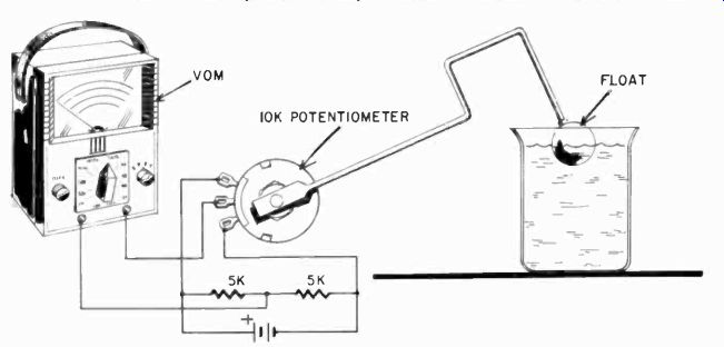
Fig. 1014. How to make a sensitive level indicator using the vom. The potentiometer
can be supported by a metal U-bracket fastened to a wooden base. The "sensitivity" of
this system will be determined by the length of the arm going from the potentiometer
to the float and by the setting of the range selector of the VOM.
Measuring temperature
Temperatures in the lab can be indicated by thermistors using the same circuit we showed for the humidity indicator, but leaving out the wet wick. In that case the instrument is automatically compensated for ambient temperature and would indicate a temperature rise directly. Another method using the VOM for indicating temperatures is with the aid of thermocouples. Thermocouples consist of two dissimilar wires which, when heated, will develop a voltage across their junction. This voltage is usually not more than about 50 my but, on a 50 ua scale of a VOM with 20,000-ohms-per-volt sensitivity, this gets the needle up half-scale. If you want a more sensitive instrument, one of the transistor amplifiers will do the job. In this case you need dc amplification.
A third method for using the VOM to indicate temperatures in the lab is with the help of a temperature resistance "bulb." This is a bobbin full of wire, generally with a large temperature co efficient. Copper wire is used, but platinum wire has a more linear change with temperature, and nickel wire has greater resistance change per unit of temperature change. The "bulb" can be made in various shapes and resistance values, depending greatly upon the needs, the dimensions required, the possible protection needed, etc. Resistance bulbs cannot he used for temperatures beyond the capabilities of the insulation, and for this reason most of them are used up to about 250° F, but wire with special heat-resisting insulation is available for higher temperatures. The VOM is ideal for this kind of measurement, since it has resistance scales ready-made. A calibration curve for temperature can be made with the help of a good thermometer, but also simply with a temperature/resistance change curve for the particular metal used. Physics handbooks will contain the necessary information.
Sensitive balance
A very sensitive balance can be made from a butterfly capacitor, using the VOM as a null indicator, but this must be used in an ac bridge. Since the VOM's ac scales are by no means the most sensitive part of the instrument, better results are obtained with diode rectifiers and the micro-amp scales. The idea is shown in Fig. 1015.
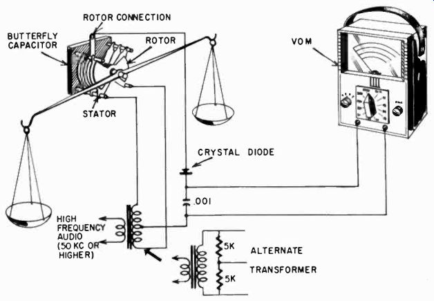
Fig. 1015. Sensitive balance using an ac bridge, the VOM and a butterfly capacitor.
Use the largest butterfly capacitor you can obtain. An alternate transformer setup is shown in the event that a center-tapped transformer isn't available.
Most butterfly capacitors are supplied with ball bearings and rotate very easily. An arm fastened to the shaft can carry the weights and balance scales. The circuit is again a bridge circuit, but this time with a low-voltage ac supply and diodes for rectification.
The sensitivity of this arrangement depends partially on the circuit values, but of course also on the length of the arms, their weight and the friction in the ball bearings. The swinging arm should be slung very slightly below the center of the shaft. This gives the arm a slight tendency to come to rest in a balance position. Without this, it would never come to rest completely. however, this arrangement detracts from the sensitivity just a little.
If you want maximum sensitivity, you can depend on the scales to lower the center of gravity a little, and arrange the arm exactly in the center of the shaft. The setup can be made even more sensitive by using a transistor null-detector amplifier for the VOM, but you will find that the electrical sensitivity soon exceeds the mechanical excellence of the shaft supports, and irregularities in the ball bearings will begin to show up as sudden little jumps in the meter.
Measuring viscosity
Measuring with a VOM the current supplied to a small dc motor can give us a measure of the viscosity of a liquid, if the shaft of the motor is supplied with a little paddle which rotates in the liquid, but of course here we must make sure that the paddle is always fully submerged. This, in effect, is the principle used in some commercial viscosity meters. If you want only a temporary relative viscosity indicator, the VOM can serve nicely for this purpose.
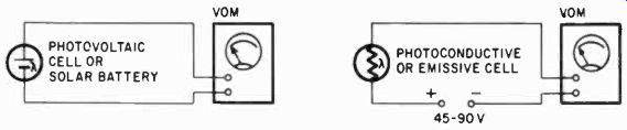
Fig. 1016. Simple photometric circuits using the VOM.
Photometric measurements
The VOM can be used in simple photoelectric circuits for all kinds of photometric measurements. Thus, not only absolute amounts of light, but also such items as density of photographic negatives, density of liquids in glass vessels, reflection of surfaces and the relative light output of phosphors can be measured. For the so-called photovoltaic cells, nothing more is needed than the cell and the VOM. These cells have been in use for many years in photometers for photographic purposes and usually are made of cesium oxide. The later photovoltaic cells are the silicon type of semiconductor material, so-called solar batteries, which put out a lot more voltage than the cesium oxide cells.
For the photoemissive and photoconductive cells, (the latter is usually cadmium sulfide), a battery is also needed. This generally needs to be more than is available in the VOM resistance ranges, where 15 volts is about the maximum. The cadmium sulfide cells usually need about 40 volts, and the vacuum-tube type about 90.
Fig. 1016 shows the two circuits, which, as you can see, are very simple indeed.
The "transistor" photocells on the market are of two kinds, both photoconductive and photoemissive cells being manufactured. These use the same kind of a circuit with lower voltages, of ten not more than 1.5. With transistors, polarity is important, since reverse polarity can destroy the cell. Polarity is also important in vacuum-tube type cells: with the wrong polarity the cell will not function, but it is not destroyed, as the semiconductor cells are.
Biophysical measurements
There are many other kinds of measurements for which the VOM can be used in the laboratory. For example, it can be used for psychophysical measurements. One of these is the measurement of skin resistance. This is often done with a bridge circuit, which will, of course, register changes quite drastically. For this you would set up a bridge where the unknown is approximately 40,000 to 60,000 ohms. Contact with the skin can be made with two small glasses with electrodes in them, with the glasses filled with a saturated salt solution. Ordinary kitchen salt will serve.
Most biophysical measurements deal with such small values that the VOM cannot be used without amplification. Some of the sensitive amplifiers we have discussed can be used, but generally more amplification is needed, hence it will be more profitable to use some other kind of instrument.
Checking electrolysis
One miscellaneous use for the VOM is checking for electrolysis. When dissimilar metals are in contact in an electrolytic medium, there will almost certainly be electrolysis, since the two metals will form a battery of sorts. Electrolysis will be particularly en countered on boats; it will show up even in fresh water. The VOM can tell you whether any voltage is present. This may only he a fraction of a volt, and the VOM will show something but even a little is too much. If the meter deflects at all on its most sensitive scale, electrolysis is taking place.
Ground resistance
Many installations using electronic and medical equipment need very good grounds, in some cases- for electronic reasons and in others for safety. The low-resistance scale can be used to measure ground resistance.
Ground resistance is extremely important in transmitter installations and it is usually specified that the ground must have a resistance of less than 5 ohms. The way to measure it is to use a temporary rod near the ground rod, driven approximately the same depth, and then to measure the resistance between the two.
Each ground rod will then have approximately half the resistance.
To make the reading more meaningful, the extra rod should be moved around in a radius of several feet, and readings taken in various places to get an average. Ground resistance varies a good deal during the year; in fact specifications usually demand that the ground be measured at the time of delivery of the job.
There are several other methods of measuring ground resistance, all of them more involved than the one we have described, and the details can be found in an electrical engineering hand book. Once you have established a good ground it can also serve to discover electrolysis voltages on pipes, simply by measuring for a voltage difference between the ground and the pipe. If you can get a deflection on the lowest voltage scale of the VOM, you can be sure the pipes will not last very long.
The VOM in industry
Naturally, when we take on big areas, as we have been doing in discussing VOM applications, there will be a great deal of over lap. Thus, many of the things said about receiver and transmitter as well as amplifier servicing are applicable to industrial situations. For example, an industrial sound system is no different than any other PA system with the possible exception that in industry it is likely to be larger and require more power and also more maintenance. The uses for the VOM in industrial maintenance work are so numerous that even mentioning them all would occupy an entire volume.
Industrial recorders
One of the first applications which comes to mind is the servicing of industrial recorders, which generally involve servo type amplifiers. These are often somewhat different from other kinds of amplifiers. Many of them operate with ac directly on the plates of the tubes and, understandably, they will function only when the voltage swings positive. In these cases there will always be a balancing system, so that the voltages rise and fall in two tubes 180° out of phase, and something will happen only if there is a difference in these voltages, and then only on the positive half-cycles. This is mentioned only so you will not begin by assuming that the amplifier must necessarily have a dc plate voltage, which you would fail to measure with the dc ranges of the VOM (Fig. 1017).
Many industrial controls use thyratrons, gas type tubes, and these are in a class by themselves. When you encounter thyratrons, you'll not fail to notice it for practically all of them glow with a bright purple when they are conducting. This glow results from the ionized gas in them, and this gas will stay ionized as long as there is even a low positive voltage on the anode. Thus, thyratrons will always operate with ac on the plates and even on the grid.
The most common way of controlling the current passed through a thyratron is by shifting the phase of the ac voltages on the plate and grid relative to each other. But, although the thyratron has ac applied to it, remember that it will actually pass a pulsating direct current since the electrons in the tube can go in only one direction, from the cathode to the anode. We have here the un usual situation that you have to measure applied plate voltage with the ac ranges and yet plate current must be measured with a dc range.
Also you should consider that the current measured this way is not equivalent to straight dc and that the peak current is considerably higher than will be indicated by the meter. What its actual value is cannot be measured with a current meter and, besides, it would depend on the length of time of the cycle the tube remains conducting. Peak current would have to be measured indirectly, with a resistance across which you'd measure the integrated voltage with a diode and capacitor. If the meter load is high enough, the meter will indicate almost the peak voltage developed across the resistor, the same as it would indicate almost the peak voltage across the power line.
In industry you would also service such devices as the thermistor and thermocouple temperature arrangements, and you already know how to use the VOM in those cases. Temperature bulbs are also very common.
Checking rf equipment
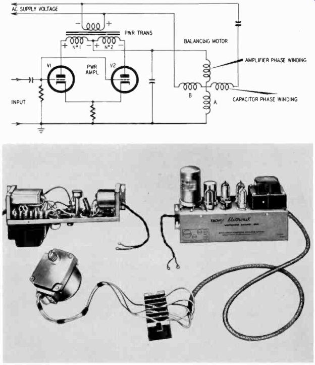
Fig. 1017. The circuit diagram shows a partial servo schematic. Each of the
tubes supplies a half-cycle of ac to the motor windings. The photograph shows
a typical servo amplifier. This unit has ac voltage on the plates of the output
tubes. (Minneapolis- Honeywell Regulator Co.)
R1 is encountered in industry when dielectric and induction heating are used. It may take forms that are not at once obvious.
For example, small bag-sealing machines are now made which don't show any obvious rf equipment, yet they use a well concealed generator in the dielectric manner. When rf is generated for industrial purposes, there isn't much reason to use filtering in the power supply. After all, with proper design, all the rf stays within the machine area. In fact, a field-strength meter made with a VOM can be used profitably here for detecting stray fields, which might require extra shielding on the machine.
A similar situation prevails with induction heating. Be careful to keep the meter itself well out of the induction work-coil field; or you might find the metal inside the plastic case fused into a neat lump of alloy. Dielectric and induction generators are adjusted almost exactly like transmitters and their circuitry is very similar, but take note of the fact generally, no filters are used, and thus the plate power supply is pulsating dc. However, for supplying generators of any size, three-phase current is usually employed, and the resulting pulsating dc will appear very nearly like a dc voltage on the meter.
Testing relays
The win can be used to check relays, encountered everywhere on the industrial scene. You can check the proper making or breaking of the contacts and the continuity, resistance and insulation values of the coils. In dc relays, corrosion of the coil wire is a common fault. This is hard to detect, except that the relay will show a tendency to close or open more slowly. Where a relay exhibits this characteristic and the voltages on the coil are normal, you can detect shorted turns by comparing the dc resistance of the coil with another coil for the same type relay.
These coils are automatically wound by machine and usually very closely similar so that, if you set up the two coils in a bridge type circuit, with the VOM as a null detector, obvious differences should show up very readily.
The industrial electronics and electric uses for the VOM include many other areas than the few samples we have mentioned, but space does not permit further discussion. Wherever electrical values must be measured, the most likely instrument to turn to is the VOM because of its many ranges and capabilities.
Caring for your meter
The most obvious care for the VOM is not putting it where it can fall. Nor should it be subjected to the extremes of cold and heat, or to strong ac magnetic fields, moisture, dirt and grease, and serious vibration. All too often, the VOM is treated with disrespect, yet the user demands all kinds of performance and ac curacy from his instrument, no matter what he has done to it.
Meter out of balance
If the meter shows signs of being out of balance, as you can readily determine by turning the instrument sideways and upside down and laying it flat, a specialist should be the one to rebalance it unless you have the skill, patience and inclination to spend a lot of time on the job.
Battery replacement
The resistance-range batteries will need periodic replacement, although with average use once a year is about as often as this needs to be done. But even if a battery needs no replacement, check it for corrosion at least once a year and preferably twice.
The corrosion products from a battery are highly conductive and could easily short other parts of the circuit if they are allowed to "grow" on the battery, as you have probably seen in flashlights which have been damp. The need for battery replacement can be detected easily; the meter refuses to allow zero setting. But even before that, if a meter shows serious discrepancies when you measure a resistance on two different ranges, the battery is weakening.
Accuracy of the resistance ranges can be checked with some standard or precision resistance, but remember that there is really nothing you an do about it except use fresh batteries, which might improve accuracy somewhat.
Cleaning the meter
A slightly damp rag with a little detergent can be used to clean the VOM case and meter face, but be sure it is only slightly damp.
A wet rag will certainly do more harm than good. Use no solvents, thinners or even carbon tet on the meter. Most of them leave an oily film or a deposit which is hard to remove. Periodic dry is the best preventive against gathering dirt on the meter.
Never leave a meter with a plastic face exposed to direct sunlight for long periods of time. If you like to have the sun shining in your shop, put the meter where the sun does not get at it. Consistent exposure to strong sunlight will discolor the plastic face and will very likely fade the lettering on the scales, making the meter difficult to read.
Checking the test leads
A periodic check should be made of the test leads. if the leads show cracks, replace them. If they feel too flexible at the plugs and prods, check to see if the strands of the flex wire are beginning to break. If so, cut the wire back an inch or so, peel the insulation and reconnect to the plugs. Make sure the contact surface of the plugs is always clean. If there is any corrosion or dirt, clean them with some very fine steel wool (not near the meter). Be sure to remove any steel-wool remnants. Remember that the test leads must be considered part of your meter and that poor contact, frayed leads and poor insulation on the leads all can contribute to lack of accuracy.
Cleaning wafer switches
Trouble is sometimes caused by the contacts of the meter switch. This is a tricky part to clean, and this must not be done unless you are certain this is the source of the trouble. If it has to be done, some very fine sandpaper cut into narrow strips and pasted to kitchen match sticks can be used to rub the contacts clean. But use no pressure on the delicate contacts beyond what is absolutely needed for the sanding. Blow out all particles carefully.
Most often you will find that the contacts are silver-plated on good quality meters and, since these are wiping contacts, the wipe of the switch will very probably keep them clean enough.
Don't expect too much from your meter. You have an instrument which is a reasonable compromise between versatility and accuracy. The manufacturer's guarantee of 2% of full-scale accuracy is almost always exceeded. But the VOM is not intended as a precision instrument in the first place. It is intended as a tool with a great many uses, and as such is the most tool you can buy for your money in any class.
Also see: Link | --Guide to VOMs and VTVMs