ALTHOUGH there are many makes of kit instruments on the market, there isn't a great variety in types. Generally the choice is limited between a sensitive 20,000-ohms-per-volt meter and the "utility" type tester which may have a 1-ma or 400-micro ampere meter. Actually, when you buy an instrument in kit form, you have, after careful assembly, the equivalent of a good quality commercial unit. Most kit manufacturers put out both the service type instrument and the smaller, less versatile one, and some of them are available in wired form as well.
Building a kit type instrument is not difficult. The assembly procedure has been broken down into simple single steps of assembly and wiring. Generally the instructions provided with it are clear and understandable though they may vary in presentation. Some manufacturers assume that the individual who is going to assemble a complicated instrument is already well versed in electronics construction, and does not need over-simplified directions. Others begin by assuming that the individual can read and identify numbed, and nothing more, and make the instructions simple enough for anyone to follow, so long as he is capable of reading at a reasonably advanced level.
Parts quality in kits is generally good, possibly even higher than in some commercial instruments. Assembly is the largest single cost item in manufacture and, since the kits eliminate this factor, the considerable saving is passed on to the customer. This gives the manufacturer more leeway in choosing quality parts. The parts are bought in tremendous quantities, giving a price advantage there. In many cases it is impossible for an individual to purchase the separate parts, even at wholesale prices, for the cost of the entire kit, which includes instructions and well-designed front panels. It is possible to give a home-built, home-designed piece of equipment the same kind of professional look that you can get in kits, but it is time-consuming and sometimes expensive to achieve. Even where it is possible to duplicate the parts for less than the kit price, there is this item of appearance, and the additional advantage that all metal parts are drilled, punched and formed.
Regardless of the form of instruction, a certain sequence of recommended procedure has been found by experience to be the best in all cases of kit construction.
1. Read over the entire instruction manual once.
2. Unpack, identify and check on the parts list all items in the kit. This will familiarize you with all the components, and will account for all parts, or disclose those which are missing (a rare event).
3. Assemble the various units of the instrument, checking each step as it is listed in the manual.
4. Solder and wire all parts, checking each step. The sequence of wiring has been carefully determined in the factory by repeated assembly of the kits by different technicians. Seldom will the various steps contain any "illogical" or impractical sequences.
6. Before final assembly, check each soldered or "to-be-soldered" joint. Sometimes assembly steps call for soldering to be deferred until a later time in the wiring. It can happen that you may overlook the soldering of a joint.
7. After final assembly and before the instrument is tested, double-check all the wiring. A good way to do this is to read once again all the steps in the manual, or at least to check all the items to see that all of them have been done.
8. Test the equipment by using all the highest ranges first.
Any mistake will then show up with the least likelihood of damage to the basic meter.
Soldering
Of great importance in building kits is the skill in soldering that the builder may have. Practically all kits manuals contain some discussion on how to make a proper soldering joint. If you are not experienced at soldering, you would do well to get some wire, solder and a soldering iron and to do some practice soldering first. Many beginners use either too much solder, or too much heat, making the solder too liquid, so that gravity will tend to flow it away from a joint. Solder at the proper heat level will barely flow and it will always move toward the point of greatest heat. If you remember this, it will make the solder's ornery behavior seem more logical. Where a part or a terminal or a wire is thickest, it will heat more slowly, but it will soon maintain more heat and consequently draw solder.
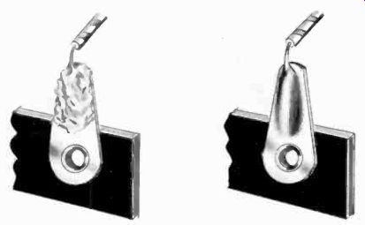
Fig. 401. The difference between a poor solder joint (left) and a good solder
job (right). Use the minimum amount of solder and heat the joint until it is
hot enough to melt it. Don't carry solder to the work on the tip of the iron.
Fig. 401 shows the difference between a properly soldered and an improperly soldered joint. On time bad joint, the solder appears rough and granulated; on the good joint, it is smooth and fills all the crevices. Where the manufacturer specifies to make the joint mechanically solid even without solder, this should be done. Even a good solder joint may not be able to take the stress of vibration or other physical forces on it.
A joint is made mechanically solid by wrapping the wire at least one turn around the terminal (as shown in Fig. 402) before soldering. There are some arguments against this, but these hold principally for temporary joints. For example, in testing and making up shunts, you might have to unsolder and resolder a joint several times. Wrapping would be nothing but a nuisance.
All kit manufacturers have a hard and fast rule about the solder that can be used. They insist, and with good reason, on rosin-core solder. No other flux may be applied to any kit part. Other fluxes sold in solder or for soldering are corrosive, and will eventually cause trouble in the kit. Manufacturers declare their guarantee of the instrument null and void if they detect any other than rosin flux in the construction of a kit sent to them for troubleshooting or repair. If you have a solder which has a flux core and if you are not absolutely sure it is rosin, get some new solder before you wire your kit. Its cost is little enough that it is not worth jeopardizing your kit's guarantee to save a few pennies.
The guarantee on kits extends also to the original condition of parts, and if they can detect (and they usually can) that a part has been mistreated, you will lose the guarantee on that part and will have to pay for its replacement.
Wiring
Wiring of the kit should be done neatly, but it is not necessarily a good idea to dress your wires together-this may increase stray circuit capacitances and reduce the frequency response follow the instructions! All ends of wires should be neatly clipped off at the solder joint, but it is much better to make the joint so that no ends are sticking out to be clipped off.
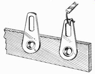
Fig. 402. The purpose of solder is to make a good electrical connection. Solder
has little mechanical strength. Wrap the wire around the joint securely before
soldering. Roth the joint and the wire must be clean.
Choosing the kit
Selection of the type of kit you need is dependent on the type of work you expect to do with it. If you are going in for serious radio service work, audio or TV repair, or advanced experimentation, you will need one of the 20,000-ohms-per-volt kits. If you expect to do some checking of electronic circuits but mostly want to have a handy portable instrument around, small, and with enough ranges to handle all your measurements, whether in the house, about the automobile or the kid's electric train, the simpler 1,000-ohms-per-volt meter will be best. If you intend to specialize primarily in appliance repair you will want to have a ready means for measuring wattage but you will not be concerned about sensitivity or measuring very low voltages and very high resistances.
Types of kits
Having discussed some of the generally applicable rules for assembly, let us look at one of the kit type instruments in a little more detail. Most kits also have large pictorial assembly plans supplied with the construction manual. If you hang these up in front of you, you will find they will help speed your work, making it easier on the eyes. It may also help prevent mistakes.
Fig. 403 shows an instrument that is slightly larger than equivalent commercial meters, because some of the assembly tricks used in commercial meters are not feasible in kit type instruments.
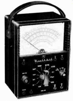
Fig. 403. Volt-ohm-milliammeter constructed from a kit. (Heath Co.)
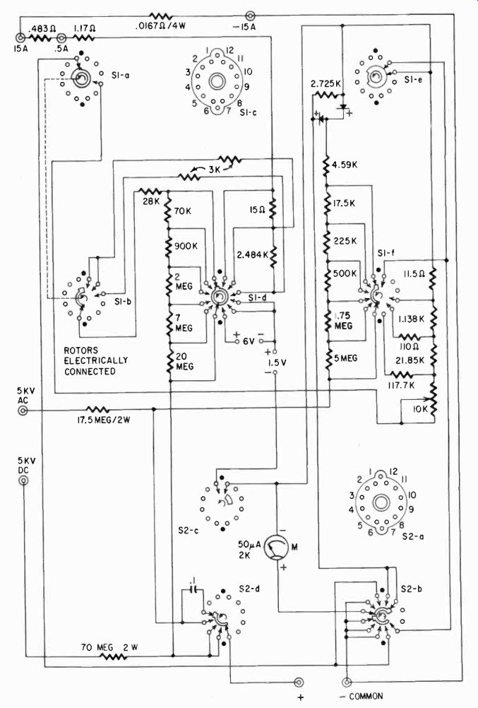
Fig. 404. Complete schematic of the VOM illustrated in Fig. 407. This is a
20,000 ohms per volt unit (dc) and 5,000 ohms-per-volt (ac).
Fig. 404 shows the complete schematic. The ranges for voltage are 1.5, 5, 50, 150, 500, 1,560 and 5,000 ac and dc. Current ranges are 150 microamperes; 15, 150, 500 milliamperes and 15 amperes.
Resistance ranges are R X 1, R X 100 and R X 10,000 with 150, 1,500 and 150,000 ohms center scale. These are representative ranges and generally what are offered in 20,000-ohms-per-volt meters. The instrument has one unusual feature: a reverse-polarity switch for the dc voltage and current ranges. This is a convenience and safety feature. It allows much faster switching of terminals when the polarity needs to be reversed.
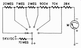
Fig. 405. This is the dc voltage circuit of the VOM whose schematic appears
in Fig. 404. The resistors are connected as series multipliers.
Fig. 405 shows the dc voltage circuit of the instrument. The meter is a 50-microampere movement having an internal resistance of 2,000 ohms.
Fig. 406 shows the ac voltage ranges. The instrument has an ac voltage sensitivity of 5,000 ohms per volt. Fig. 407 shows the current-ranges. This is the Ayrton type of shunt circuit discussed in detail in Section 3. Notice that here there is an additional series resistance in the meter circuit, which keeps the meter circuit resistance high and allows, if ever necessary, replacement of the meter .and subsequent recalibration. Separate jacks are provided for 0.5- and 15-amp ranges to avoid heavy current through the switch contacts, which are not rated for it.
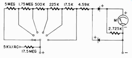
Fig. 406. Ac voltage circuit of the VOM in Fig. 404. The multiplier arrangement
is similar to that used for dc, except for the use of the rectifier diodes
and the shunt resistor across the meter.
The resistance-measuring circuit for this meter was discussed in some detail in Section 3. Fig. 408 shows the simplified circuit again. You will remember the reason for the "external" multi pliers was the need to use a higher-voltage battery on the high range.
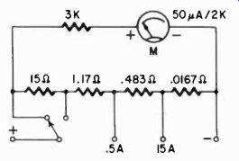
Fig. 407. Current ranges of the VOM of Fig. 404. This is an Ayrton shunt circuit.
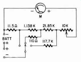
Fig. 408. The resistance-measuring circuit of the VOM of Fig. 404.
Next we come to a feature not yet discussed at all. This is the output-measuring circuit and its scales. Fig. 409 shows the basic circuit, which is essentially the same as the ac voltage circuit, but with the 0.1-microfarad capacitor in series with the terminals.
How to read decibel scales Let us first sidetrack a little and explain what a logarithm is and how it is derived. A logarithm (often abbreviated as log) is a way of writing the exponential to a power. If 102 (which is 10 x 10) = 100, then we can write log10 100 = 2. This means that .5A 15A
the base (10 in this case) must be raised to the second power (102) to give the number 100. This is a useful form of notation for it al lows us to add exponentials and get answers to multiplication problems in a simple way. Thus: log 10 100 = 2. Also, log 10 1,000
=_- 3.
And quite conveniently: log 10 (100 X 1,000) = 2 + 3 = 5.
Let us see if this is true. 100 X 1,000 = 100,000 or, to write it another way, 10^2 x 10^3 = 10^5, meaning 100,000 is 10 multiplied by itself 5 times. And this is the way we use logarithms. To make it convenient, tables have been worked out giving logarithms for all numbers.
Fig. 409. This output circuit is similar to the ac voltage arrangement shown in Fig. 406. The .1-µf capacitor is a blocking unit. As in the case of the dc voltage circuit, the resistors are series multipliers. Note the arrangement of the diodes. These are connected as shown previously in Fig. 209 (Section 2).
Long ago, telephone engineers, experimenting to find out how much they would need to increase the power in a telephone receiver so that a listener could detect that the sound was louder, found a certain amount would just be noticed. Logically they called this the "just noticeable difference," an expression which persists in psychology laboratories today. They also found that this JND could be expressed as a logarithmic function of the ratio of two power levels; the before and after increase.
Logarithms obviously turned out to be a handy way of expressing such an increase, since you could at any time add these logarithmic functions and still accurately express a product. Thus, if one sound had many times the power of another, you could use the logarithm and say there was so much difference in the power level. This log function then was given the name of bel.
To make it a handier figure, it was divided by ten and called a decibel' (deci means one-tenth).
[[And it turns out that 1 decibel is a "just noticeable difference.”]]
The telephone engineers next determined that the difference in power levels could be expressed as:
10 log 10 . decibels (db)
If we say that there has been a gain in power of 10 decibels, we can say:
10 log 10 P2= 10.
and thus:
P2 leg 10-= 1.
This means that the logarithm of the ratio of power level P1 and power level P2 is 1, or that, to get the number, we must raise 10 to the first power or 10^1. This is of course 10, meaning that 10 decibels have made the sound just 10 times as "loud." Let's try another example. Say we have a gain of 30 db.
Then:
Log 10=3.
This means that we have to raise 10 to the third power, (10^8) and we know this is 1,000.. If we have a gain of 30 db, the power in the second case is 1,000 times as much as the power in the first.
In other words, a 60-db gain means one thing is 10^8 or 1,000,000 times as great as something else. But suppose the sound is de scribed simply as 60 db's, then what does it mean? Well, to be able to measure power sensibly, we must always deal with a logarithmic function of a ratio. A ratio requires two numbers, and if we agree that we will always use the same number for one of these two, then an answer in db's will always mean the same thing to various people. Therefore, engineers decided to use one specific point of reference to give them an easy way to obtain a ratio.
This point of reference has varied from time to time, but as generally used now it is 1 milliwatt in 600 ohms. It must be in 600 ohms, because with a meter such as a VOM we can measure only ac voltage, and power is a product of current and voltage.
To get the current out of this, we simply agree to always develop the voltage across the same impedance. Knowing that the reference point is 1 mw in 600 ohms, and being told that some amplifier puts out 30 db, you will know at once that this amplifier has an output of 1,000 times 1 mw, or 1 watt. And you will also know that this 1 watt will develop a voltage of 24.5 in the 600 ohm impedance (from Ohm's law).2 Now we are at home base, for we can measure ac voltages with the VOM.
------------
2W=ExIandIxR=E. Since R is 600,thenI= 600
-E.Wisl watt. W= E2 E X E E2
- But since W = 1, we have 1 = 600
Transposing, we get E' = 600.
By taking the square root of both sides we will have E = 24.5 volts ac.
-----------
And the manufacturer has made matters even simpler, by adding a db scale on the meter. Using the 1.5 volt range on the meter shown in Fig. 403, if the meter indicates about 0.7746 volts, it also shows 0 db, since at 1 mw, 0.7746 volt will be developed in a 600 ohm impedance. Switching to the 5-volt range, you will see that, when the meter again reads 0 db, you are actually measuring a voltage of about 2.45. This works out to correspond to 10 db. We have them shifted, and must add "exponentials," so that, when we use the 5-volt range, 10 db must be added to the reading. Table 4-1 shows the addition for this particular instrument.
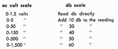
Table 4-1. Relationship ac volt scale between ac voltage and db scales db
scale
Manufacturers do not all use the same reference point. Some prefer to use another-0.6 milliwatt, developed in 500 ohms. This is an older standard. Of course, for it the db scale is different with respect to voltage. For the same db number you read more than twice the voltage. Convert to 1 milliwatt in 500 ohms by adding-8 db.
What happens when you must read output across a lower impedance, such as a speaker voice coil? A correction must be made, and we must add:
600 10 login –z
... where Z is the actual impedance of the speaker. Table 4-2 shows the additions to be made for speaker voice coils of different impedance. But remember, the speaker must be exactly matched to the amplifier actually to read the power levels correctly. To correct for 0.6 milliwatt in 600 ohms (the correction for 500 ohms was shown previously), we must use the correction for impedance.
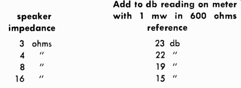
Table 4-2. Corrections to be made in output readings across low-impedance
speaker coils
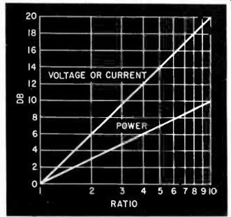
Fig. 410. Power and voltage (or current) ratios vs decibels.
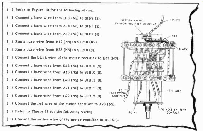
Fig. 411. Excerpt front an instruction book for a VOM kit. (Heath Co.)
In calculating the voltage developed across the resistor at a certain wattage (or db), we used the square of the voltage. And in logarithmic terms, using the square of something means that the log is twice as large. The relation between the db scale and the voltage is the square root of that relation and the power. To state it in another way, the power relation is the square of the voltage relation, which in terms of db and ratio works out as just half. Fig. 410 shows the relationships between power and voltage ratios and db's. Plotted on semilog paper, these look like straight lines.
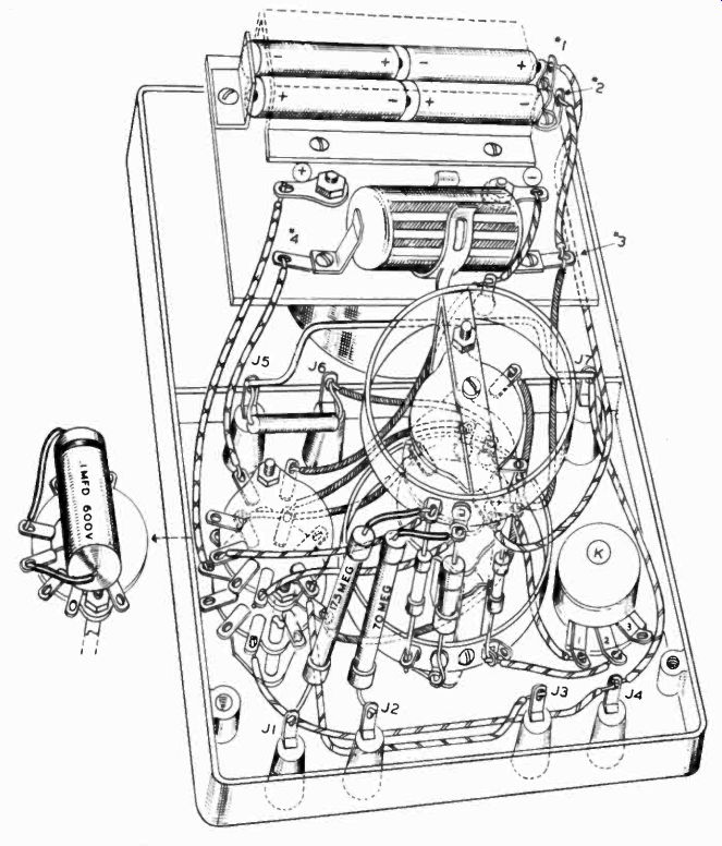
Fig. 412. Type of pictorial supplied with a vow kit. (Heath Co.) If you read
the voltage scales as well as the db scales, you may find the addition of a
round number of db's as you change scale may not be perfectly accurate. But
consider that if you drop 1 db. From the addition you only lose 1 milliwatt,
and you can see that extreme accuracy is not required.
Assembly instructions
Fig. 411 is a short section of the instructions which actually come with the instrument shown in Fig. 403 and you can see that they are stated in single, unambiguous steps. NS stands for "no solder" when another wire is expected to be put on the same terminal, and S stands for "solder" when all the wires have been put on the terminal. This particular section is concerned with the Fig. 413. Front view of a smaller type of VOM wiring of the range switch, and the clear drawing accompanying it is also shown. Fig. 412 shows one of the overall pictorials sup plied to make the wiring job easier. These pictorials are also provided in a large version to hang on the wall.
Sometimes the instrument is not as complicated, and the wiring can be shown completely in one pictorial; for example, the less sensitive instrument, illustrated in Fig. 413. Its interior views (Fig. 414) picture the complete wiring of the instrument. The schematic that goes with this is diagrammed in Fig. 415, which shows at the bottom the same kind of breakdown into single function circuits as was given earlier.
The low ohms range is a potentiometer range, but the high ohms range is, in effect, a series-type ohmmeter circuit. Notice that the meter in this instrument is a 400-microampere unit, but that in both current ranges it is never directly connected to the circuit without a shunt.
Ranges for the tester are 10, 30, 300, 1,000 and 5,000 volts ac and dc; 0-3000 and 0-300,000 ohms; 10 ma and 100 ma. These ranges were clearly designed for general utility and not specifically for electronic service work.
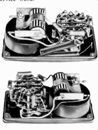
Fig. 414. Two interior views of the compact VOM shown in Fig. 413.
Another instrument supplied in kit form is illustrated in Fig. 416. This has a pictorial similar to those described earlier but entirely different kinds of instructions are supplied with the kit.
In place of the verbally explicit instructions, these kits come with simple lists of steps, as typified by the section shown in Fig. 417.
Here the step number is listed, then the part or wire, and the instructions say from where to where this must be installed, with a reference to the pictorial to be used. Here the reference C means "do not solder" and S means "solder." This type of instruction obviously requires a little more experience in electronic assembly, although special or difficult wiring or assembly points are given more explanation. Incidentally, this is a common approach to instructions, and, once you get used to it, the directions are not difficult to follow.
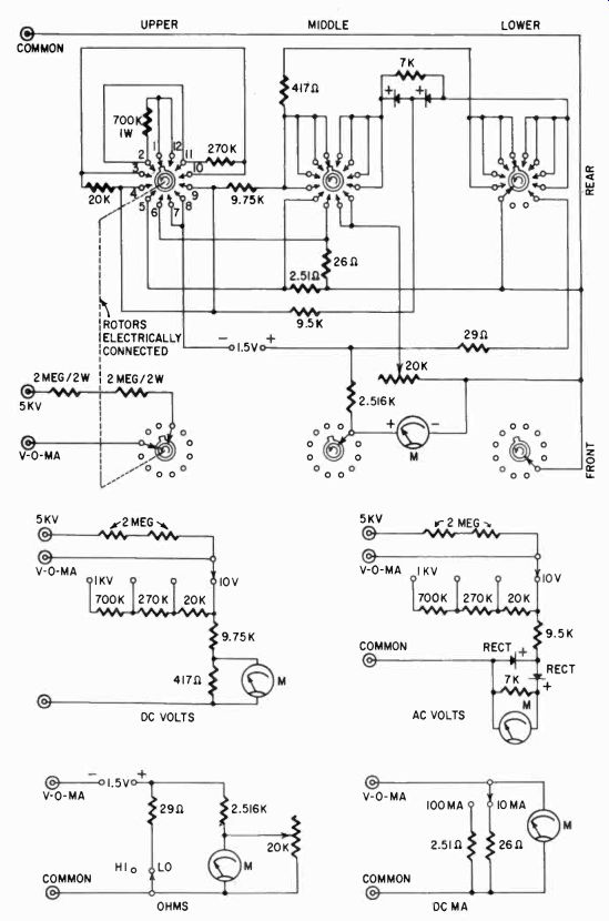
Fig. 415. Schematic diagram of the VOM of Fig. 413. The smaller schematic
are simplified versions of each of the functions.
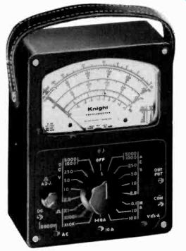
Fig. 416. This is a vom having a sensitivity of 20,000 ohms per volt. It was
constructed from a kit. (Allied Radio)
Tools
None of these kits call for the use of any special tools. A medium or small screwdriver, a pair of pliers and a soldering iron will just about handle the work. An additional pair of small side cutters and a simple wire stripper will speed it a little. No special calibration tools are required. The fresh flashlight battery is used to test the low-voltage dc ranges, and the manual recommends the use of a filament transformer for checking the ac voltage function.
Dc ranges are checked by drawing an appropriate amount of current for each range from a small battery through a series resistor. Ohms ranges need only be checked with their test leads shorted to see if the meter can be set to zero, which is on the right-hand side of the scale.
If you have wondered why these kits, which include everything but the solder, do not contain this last item, the answer is that this is a legal matter. Providing almost everything to build an instrument prevents some kinds of litigation.
There are many makes of kit type VOM's, but essentially they are supplied in the three classes we have discussed, and those we have covered are representative of the products offered. Building kits is a lot of fun, and you will own an instrument on a par with some of the best commercial equipment. It is certainly a lot less trouble, and more economical than designing your own.
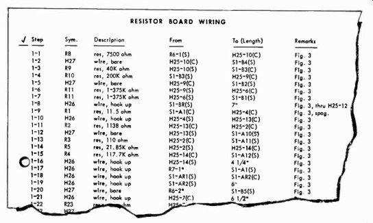
Fig. 417. Sample instruction sheet for wiring the kit shown in Fig. 416.
Also see: Link | --Guide to VOMs and VTVMs