A. BASIC DEFINITIONS.
The following definitions of fundamental resistor terms are presented for the purpose of establishing a basis of discussion and understanding. The recurrent use of these terms without a clear and concise appreciation of their significance would lead to misconceptions.
For a more complete list of definitions and functions refer to Section VIII, DEFINITIONS.
1. Resistance--Resistance is the (scalar) property of an electric circuit or of any body that may be used as part of an electric circuit which determines for a given current the rate at which electrical energy is converted into heat or radiant energy and which has a value such that the product of the resistance and the square of the current gives the rate of conversion of energy.
In the general case, resistance is a function of the current, but the term is most commonly used in connection with circuits when the resistance is independent of the current.
2. Resistor-A resistor is a device, the primary purpose of which is to introduce resistance into an electric circuit.*
3. Conductor--A conductor is a body so constructed from conducting material that it may be used as a carrier of electric current.*
4. Resistive Conductor--A resistive conductor is a conductor used primarily because it possesses the property of high electric resistance.*
5. Hot Spot-The hot spot is the point or location of maximum measurable temperature on the surface of a device.
* ASA Standard
6. Ambient Temperature--Ambient temperature is the temperature of the surrounding cooling medium, such as gas or liquid, which comes into contact with the heated parts of the apparatus.*
7. Test Conditions--Two optimum, or laboratory, conditions are generally understood to he true when ratings of resistors are discussed, namely, free space and still air.
a. Free space. Free space is that condition wherein no physical object is within one foot of any part of the resistor, or resistor assembly, under consideration.
h. Still air. Still air is considered to he air having no circulation other than that due to convection currents created by the heat of the resistor being operated.
c. The expression "Free Air" is used through out the text to denote both conditions of free space and still air.
d. Throughout this book, ambient temperature shall be considered 40°C unless otherwise specified.
B. PERFORMANCE STANDARDS. The electrical energy dissipated by a resistor is converted into heat energy. The ultimate temperature rise of intermittent-duty resistors is governed largely by the watt input, the time cycle, and by the mass and specific heat of the entire assembly. The larger the watt in put and the shorter the time-on period, the more important are the mass and specific heat of the material.
With continuous-duty resistors the ultimate temperature rise is obtained when stability is reached between the heat radiated, plus that carried off by conduction and convection, and the heat generated by the I^2R loss.
1. Temperature Test-Resistors
a. When a temperature test is made on an intermittent duty resistor, the resistor should he connected to a voltage that would give the root mean square
• ASA Standard
current of the cycle continuously for the "time on" period specified. The specified cycles of "time on" and "time off" shall be repeated for one hour.
For temperature tests on intermittent duty resistors for D.C. and A.C. motor starting purposes, refer to NEMA Standards IC1-4.3 and IC1-4.5, Pages 150 and 151 respectively.
b. When a temperature test is made on a continuous-duty resistor without its motor, any tested step shall be subjected to 100 percent of the current for which it is designed, and this value of current shall be maintained until the maximum temperatures are reached.**
c. When a temperature test is made on a rheostatic dimmer, it shall be made on a single plate which is operated at rated voltage and connected in series with lamps totaling the rated lamp load.**
2. Temperature of Resistors
a. When a temperature test is made on a resistor, rheostat or dimmer at the current values, duty cycle and elapsed time specified, the limiting temperature rise above the cooling air and the methods of temperature measurement shall be as follows:
(1) For bare resistive conductors, the temperature rise shall not exceed 375°C as measured by a thermo couple in contact with the resistive conductor.
(2) For resistor units, rheostats and wall-mounted rheostatic dimmers which have an embedded resistive conductor, the temperature rise shall not exceed 300°C as measured by a thermocouple in contact with the surf ace of the embedding material.
(3) For rheostatic dimmers which have embedded resistive conductors and which are arranged for mounting on switchboards or in non-combustible frames, the temperature rise shall not exceed 350°C as measured by a thermocouple in contact with the surface of the em bedding material.
(4) The temperature rise of the issuing air shall
* *NEMA Standard
not exceed 175°C as measured by a mercury thermometer at a distance of 1 inch from the enclosure.**
C. WIRE OR RIBBON POWER TYPE RESISTORS.
A non-functional breakdown of basic power resistor types indicates the following four variations:
1. Fixed Resistor-A fixed resistor is one designed to introduce only one predetermined amount of resistance into an electrical circuit.
2. Tapped Resistor-A tapped resistor is one designed to introduce one of several predetermined amounts of resistance into an electrical circuit, dependent upon the number of resistor terminals employed.
3. Adjustable Resistor--An adjustable resistor is a resistor so constructed that its resistance can be readily changed over values within its range.
4. Multi-section Resistor--A multi-section resistor is a resistor having two or more electrically independent sections.
For complete analysis of resistor types and functional applications, refer to Section III, TYPES OF RESISTORS. D. BASIC POWER RESISTOR FUNCTIONS.
Although every resistor basically performs the prime function of introducing resistance into an electrical circuit, and thereby converting electrical energy into heat energy, this may he done for several different practical reasons.
1. Heating--Resistors are often employed in order to use directly the heat energy generated. Electric stoves, toasters, irons, and numerous other devices make direct use of the heat energy generated by the flow of electrical current through a resistive conductor.
2. Current Limiting--It is often necessary to restrict the amount of current flow through a particular circuit or portion thereof. The introduction of a resistor into the circuit performs this function. For the proper value
* *NEMA Standard
of resistance to be inserted, refer to Section E, FUNDAMENTAL RESISTANCE CALCULATIONS.
3. Voltage Drop—A “voltage dropping" resistor is one whose main purpose is to reduce the applied voltage for a particular application. The reduction in voltage is a function of the current through the resistor and the resistance value (E=IR).
4. Voltage Divider--A "voltage divider" resistor provides the voltages required for various circuits when each circuit is drawing a predetermined current through the divider.
5. Discharge--It is advisable to discharge the stored energy in certain circuits to prevent damage to electrical equipment from excess voltage surges. This is accomplished by discharging the stored energy through a resistor.
E. FUNDAMENTAL RESISTANCE CALCULATIONS. The computation of resistance values is actually the determination of the relationship existing between electrical potential in volts, current in amperes, and the resistance value in ohms. Ohm's Law is the rule for determining the relationship.
I. Ohm's Law--This fundamental law of the electric circuit may be stated as follows: The current in a circuit is directly proportional to the circuit EMF ( electromotive force) and inversely proportional to the circuit resistance.
Ohm's Law may be expressed in three ways as follows: R equals E over I (E divided by I) R = I equals E over R (E divided by R) I E equals I times R E E I E R IX R
where R is resistance in ohms, I is current in amperes, and E is electrical potential in volts.
Example 1: Knowing the voltage in a circuit to he 6 volts and the current to he 0.6 ampere, the resistance value is found as follows:
E 6 R = - = - = 10 ohms I 0.6
Example 2: Having a voltage supply of 6 volts to feed a vacuum tube filament that operates at 1.5 volts and draws 0.25 amperes, first subtract 1.5 from 6 to obtain the voltage drop across the dropping resistor which, in this case, is 4.5 volts. Then apply the formula as follows to find the resistance value necessary: R = E = 4· 5 = 18 ohms I 0.25 Example 3: It is desired to determine the voltage drop across a 20 ohm resistor in which the current is 0.25 amperes. The voltage drop is found as follows:
E = I X R = 0.25 X 20 = 5 volts
2. Ohm's Law Nomograph--The Ohm's Law nomograph, Figure 1-1, provides a ready graphical solution to Ohm's Law problems, as illustrated by the following example: To find the current flowing through a 10 ohm resistor connected across a 115 volt supply draw a line from 10 on the R scale to 115 on the E scale and read the answer where the line crosses the I scale, i.e., 11.5 amperes.
Similarly, the resistance may be determined, given the voltage and current, and the voltage may be obtained knowing the current and resistance.
3. Resistors in Series--When resistors are connected in series, the total resistance is obtained by adding all values together. Thus, if a 5 ohm, a 10 ohm, and a 15 ohm resistor are connected in series, the total value is 5 + 10 + 15 = 30 ohms.
R_TOTAL = R1 + R2 + Ra . . . . . . . . + R0 Ohms
Use numbers on the left with numbers on the left only, and numbers on the right with numbers on the right only.
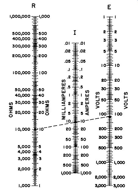
Figure 1-1. Ohm's Law Nomograph
The Ohm's law nomograph is equally applicable to resistors in series, using RrnTAL in lieu of the single resistor given in the example.
4. Resistors in Parallel
For resistors in parallel:
Total Resistance RT ---- 1
----ohms 1 1 1 1
R1 + R2 + R3 ...... Rn
For two resistors in parallel: R1 X R2
Total resistance RT = R1 + R2
When the resistance of one resistor and the total resistance are known, the formula is conveniently written:
R2 = RT X R1 R1 - RT
When the resistance values are all equal, the total parallel resistance is equal to the resistance of one resistor divided by the number of resistors. For example, the total resistance of two equal resistors in parallel is one-half that of one, while the parallel resistance of three equal resistances is one-third that of one.
Example 1: Find the overall resistance when an 8 ohm, a 20 ohm, and a 40 ohm resistor are connected in parallel.
Applying the formula:
1 Rr=-------
_!_ + _!_ + _!_ R1 R2 Ila 1 1 8 40 5 ohms
5. Parallel Resistance Nomograph--This graphical device, Figure 1-2, enables the total resistance of two or more resistors in parallel to he determined readily. The dotted lines indicate the solution of an example involving three resistors of 15, 10 and 5 ohms respectively.
Draw a line from 10 on scale A to 15 on scale B.
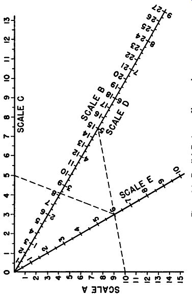
Figure 1-2
Where this line cuts scale E is the total resistance of 10 ohms and 15 ohms in parallel, or 6 ohms. Now draw a line from 6 on scale E to 5 on scale C. Where the second line cuts scale D is the total resistance of all three in parallel, or 2.73 ohms.
To add a fourth resistor in parallel, use 2.73 on scale A and the fourth resistor on scale B. More resistors may be added in a similar manner.
The units on the nomograph may be multiplied by any multiple of 10 in order to solve problems dealing with higher resistance values. If one scale is multiplied all the others must also be multiplied in the same manner.
6. Kirchoff's Laws--In the solution of circuit problems, two fundamental relationships known as Kirchoff's Laws may be used. These are: Current: The algebraic sum of the currents flowing toward any junction point is zero.
Voltage: The algebraic sum of the voltages around any closed path in a network is zero.
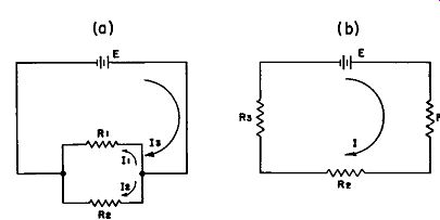
Figure 1-3. Illustration of Kirchoff's Laws In Figure 1-3a, assume that E=10
volts, R1=2 ohms, R2=5 ohms. Then, using Kirchoff's Law for current:
Ia = I1 + I2
From Ohm's Law:
I1 = E/R1 = 10 /2 = 5 amperes
I2 = E /R2 = 10 /5 = 2 amperes
Therefore, Ia = 5 + 2 = 7 amperes
In Figure 1-3b, assume that E = 10 volts, R1 = 1 ohm, R2 = 2 ohms, Ra = 5 ohms.
Then using Kirchoff's Law for voltage and Ohm's Law: E = IR1 + IR2 + IRa and I= E/(R1 + R2 +Ra)= 10/8 = 1.25 amperes.
Therefore, E = 1.25 x 1 + 1.25 x 2 + 1.25 x 5 = 10 volts.
Or, 10 volts = 10 volts, the voltage rise through the voltage source being equal to the sum of the voltage drops around the closed circuit.
7. Wye and Delta Resistance Combinations.
In circuit calculations it is often convenient to make use of a mathematical device known as delta-wye ( or wye-delta) conversion. For example, referring to Figure 1-4, a delta circuit consisting of resistors A, B and C, and having terminals 1, 2 and 3, may be replaced by an equivalent wye consisting of resistors a, b and c.
The following equations apply: Conversion from delta to wye:
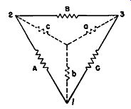
Figure 1-4. Conversion from wye to delta:
Power Rating and Current Carrying Capacity
Resistors are rated in watts, also in current carrying capacity, and as the resistance value of a resistor of a given watt rating is increased the current carrying capacity decreases. If the current flowing through a resistor of a given size and watt rating exceeds that as deter mined by the formulas presented below, the resistor will be overloaded and it will generate more heat than if operated at its rated current carrying capacity. Over loading tends to shorten the life of a resistor. Also, other apparatus in the circuit may be damaged by the excessive temperature rise of the resistor.
The basic formula for power is as follows:
W equals E times I W = EX I w E equals W over I (W divided by I) E I I equals W over E (W divided by E) w I= -E
Where W is power in watts, E is electrical potential in volts, and I is current in amperes.
By substituting the values of E and I as determined by applying Ohm's Law, we obtain other formulas as follows:
W equals I squared times R I equals the square root of W over R R equals W over I squared W equals E squared over R W = 12R I= ?: w R= 12 W = E2 R
E equals the square root of R times W E = yR X W R equals E squared over W R = E2 w
The following examples will show some applications of the formulas: Example 1: Find the current carrying capacity of a 20 watt resistor of 5 ohms.
I = ? ';- = ? 2 i = ? --; = 2 amperes
Example 2:
Find the required watt rating of a 20 ohm resistor to carry 1 ampere: W = 1 2 R = (1)2 X 20 = 1 X 20 = 20 watts
9. Ohm's Law Table for Direct Current Circuits
The following table conveniently summarizes the various forms of Ohm's Law previously explained. In using the formulas for the solution of problems make sure that a consistent system of units is employed. Reduce all terms to volts, amperes and watts. 5 K.W. must be expressed as 5000 watts, 70 milliamperes as 0.070 amperes, 5 megohms as 5,000,000 ohms.
Ohm's Law Equations for D.C. Circuits
10. Ohm's Law Table for Alternating Current--The previously explained equations refer to resistors in D.C. circuits. For A.C. circuits involving inductive or capacitive reactances in addition to resistance, the equations in the following table should he used.
----------- Ohm's Law Equations for Single Phase A.C. Circuits
C = Capacitance
XL = Inductive Reactance
L = Inductance
Z = Impedance
Xe = Capacitive Reactance
a = Angle of lead or lag
f = Frequency
11. Wire Resistance--The resistance of a conductor is a function of its length, area and resistivity. The equation for the resistance of a wire of length 1 (in feet) and cross-sectional area A (in circular mils) is:
R = l!_l
A where p is the resistivity of the conductor expressed in ohms per circular-mil-foot. A circular mil is a unit of area given by A = d2, where d is the diameter of the wire in mils (thousands of an inch). One square inch of wire therefore contains 1,273,240 circular mils. At a temperature of 20°C, p for copper is 10.37 ohms per circular-mil-foot.
The resistance of a conductor changes to some extent with temperature. The change may be calculated from the temperature coefficient of resistivity. With some metals and alloys the change in resistance with increase or decrease in temperature can be considered a straight line function over the range of temperature usually encountered. With other alloys and metals the change in resistance with temperature change may be negative over a certain temperature range, and positive over a different temperature range.
The temperature coefficient of resistivity may be expressed as:
a = Rt2 - Rtl Rt1 (t2 - t1)
or Rt2
= Rt1
[l + a (t2 - t1)] where Rt1 and Rt 2
... are the resistances in ohms at temperatures t1 and t 2, degrees centigrade, respectively and a is the temperature coefficient of resistivity.
For copper, the temperature coefficient of resistivity is .00393, t1 being taken as 20°C for convenience.
Thus, for a copper resistor, whose resistance at 20°C is 50 ohms, a 100°C rise in temperature would increase the resistance to:
R2 = 50 (1 + .00393 X 100) = 50 X 1.393 = 69.6 ohms
The temperature coefficient of resistivity of a typical nickel chromium alloy (Ni-Cr:80-20) is 0.00013 at 20°C. A 50 ohm resistor of this material, subjected to the same temperature rise of 100°C would have its resistance increased to:
R2 = 50 (1+ .00013 X 100) = 50 X 1.013 = 50.6 ohms
The above examples illustrate the wide variation in performance that can be obtained, depending on the materials used in the manufacture of a resistor.