A review of the various types of transducer available
by SK.
[Note: * "Thou" = 1,000th of an inch. ]
By definition a phono cartridge should translate the information stored mechanically in the groove of a phono record into an exactly corresponding electrical signal. As is well known, it accomplishes this feat by the application of motion from a modulated V-shaped groove in the phono record via a hemispherical stylus coupled to the actual transducer element. In the case of two- channel "stereo" records the two groove walls are independently modulated. Therefore, the parameters of the record groove and the record material are major factors affecting the performance of the cartridge.
Present-day styli are either sapphire or diamond, and are several orders of magnitude harder than the record material. Therefore upon the application of pressure between the stylus and the record it is the record rather than the stylus that deforms. The contact area of the stylus tip and the record groove will be a function of the effective force between the two surfaces and the mechanical constants of the record, and the attrition of the stylus will be strictly a function of this contact area and the length of travel of the stylus. This latter factor is usually equated in terms of playing time. It has been determined experimentally that at playing weights greater than about 0.5 gram the record material is stressed beyond its elastic limit 3, 4 and it is the aim of cartridge designers to produce cartridges which will satisfactorily track heavily modulated records at playing weights below this figure. Therefore in the interests of reduced record wear and concomitantly stylus wear, the ideal limit would obviously be playing weights less than 0.5 gram, and certainly 1.5 grams can be taken as the upper limit to maintain maximum record life.
Despite many extravagant advertising claims, there are probably fewer than a dozen cartridge cartridges produced today which actually track all music records at playing weights less than 1.5 grams.
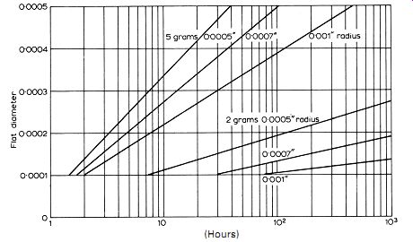
Fig. 1. Playing time for flat diameter diamond styli.
Stylus wear is generally expressed as the size of " flat" developed at the point of contact with the record, and is a complex function of playing weight, stylus dimensions, record material, and the dynamic mechanical constants of the cartridge referred to the stylus tip.
Fig. 1 shows the life of a diamond stylus at two playing weights, 2 grams and 5 grams, and for different radii. It will be seen that even at only 2 grams playing weight with an 0.5 thou* stylus point, the life is only 500 hours for a "flat" diameter of 0.25 thou, which with wide-range low-distortion equipment is currently accepted as being the maximum "flat" diameter to be tolerated. Increasing the stylus diameter to 0.7 or 1 thou considerably reduces stylus wear but at the expense of increased tracing distortion. The elimination of tracing distortion requires a stylus of minimum tip radius-ideally zero!--but apart from stylus life other factors control the minimum tip radius. The bottom of the record groove is not infinitely sharp; with commercial pressings it is of an indeterminate radius. This is maintained at minimal value by the record manufacturers but can sometimes approach 0.5 thou! Indeed, until the advent of stereo recording the groove bottom radius was not under strict manufacturing control and some of the earlier L.P. pressings are unplayable if the tip radius of the stylus is less than 1 thou.
The elliptical or biradial tip has been evolved to overcome the difficulty. The major radius-across the groove-is of the order of 0.7 thou, whilst the minor or "working" radius can be as small as 0.2 thou with consequent reduction in tracing distortion, although stylus life is reduced accordingly. The upper limit for the major axis is 0.7 thou because under conditions of maximum vertical modulation the groove width can be (and often is) instantaneously reduced to 1 thou; thus if the tip radius (either spherical or the major axis of an elliptical) is greater than 0.7 thou the stylus will ride on the interface of the groove and the record land with the possibility of groove jumping in addition to the increased distortion.
One specifies a given dimension and euphemistically hopes that this dimension will be achieved. Modern production methods work to incredibly fine tolerances and ± 0.1 thou is the norm for tip radius limits. Thus a maximum specified radius of 0.7 thou in reality means a dimension of between 0.5 and 0. 7 thou although by selection closer tolerances can be achieved. Even so, using optical methods of measurement the confidence limits of the measuring equipment are usually of the order of ±1 micron (one twenty-fifth of a thou) which sets a practical limit.
The projected use of the metric system throughout our commercial and industrial life and the introduction of SI units for all scientific work poses a number of problems at all levels of industry. This is especially exemplified in design and production of phono cartridges where dimensions are microscopic-masses of the order of milligrams, length in microns or tenths of a thou-and to this author at least it seems ridiculous to think of a milligram as 10^-6 kilogram and the micron as 10^-6 meter. The magnet industry both in this country and the United States and the cartridge manufacturers throughout the world all insist on specifying their products in c.g.s. units.
[Conversations with many commercial and technical personnel indicate an obdurate insistence on the familiar, thus c.g.s units are used in this article.] Before specifying the parameters of a cartridge it is necessary to know the maximum modulated levels available from the record. These levels are controlled at low frequencies by the maximum groove displacement (normally 0.005 cm) and at higher frequencies by stylus tip dimensions and groove velocity. Fig. 2 shows these limits. Curve A relates r.m.s. velocity to maximum displacement, and B, C, D, and E to stylus tip radius: G is the generally accepted maximum velocity for music records although these values are sometimes exceeded, especially on "gimmick" and "pop" records. From this graph it would appear that mis-tracking must occur with all styli in which the radius is greater than 0.0003 inch; this assumption is modified by the fact of record deformation, but is nevertheless substantially correct for the inner grooves at high modulation levels. These limitations are reduced as the groove diameter increases and at diameters exceeding about 7 inches are negligible even for 0.0007 inch tip radius.
The basic design requirements for a cartridge are fundamentally mechanical and relate to the dynamics of the moving system and one must design to track the maximum velocities shown in Fig. 2. It is convenient to divide the frequency spectrum into three sections: (a) below about 500Hz; (b) 500 to 5000Hz; and (c) above 5kHz. One can relate Fig. 2 to maximum "needle tip impedance" that is, the mechanical impedance at the stylus point when in contact with the record, for a given playing weight. Fig. 3 relates this premise for a playing weight of 1.5 grams, using curves A and B as limits.
The dotted lines refer to a compliance of 5 ×10^6 cm/dyne and mass of 2.25 milligrams.
These values may be modified by other considerations: (1) the record compliance-stylus mass resonance and the head mass/restoring force compliance resonance should be outside the recorded frequency range; (2) appreciable amounts of damping may be introduced. The high-frequency resonance can be evaluated assuming a record compliance of 3 ×10^-8 cm/dyne. The low- frequency resonance is controlled by the mass moment of inertia of the arm plus cartridge related to the stylus tip and the cartridge compliance; it should be less than 22.5 Hz (the "slip" frequency of most induction motors used in turntables and a frequent source of "rumble") and above 10 Hz-at lower frequencies than this value the cartridge system becomes very sensitive to external vibrations; and the motor board must be adequately decoupled to prevent shock excitation of the cartridge and attendant acrobatic antics across the record surface.
It is generally assumed that compliance and stylus tip mass are the usual parameters hopefully specified by the manufacturer in relation to the mechanical constants of the cartridge, but especially with highly damped systems the "loss" component achieves major importance in the mid-band frequencies, thus the evaluation of input mechanical impedance is necessary to the design engineer. Of more immediate importance to the user is the minimum playing weight for tracking music records.
One method is to produce a disc with a (slow) sweep frequency covering the major frequency range (say, 80 Hz to 8 kHz) at maximum music modulation levels. In use the output from the cartridge is observed on a cathode-ray oscilloscope and the playing weight is reduced until a "break" occurs on the waveform usually at the point of maximum acceleration. A disc (7 inch 33 1/3 r.p.m., 80 Hz to 8 kHz) has been produced as a tentative industry standard and the modulation levels are shown in curve G on Fig. 2.
The disc has "left" channel information on one side and "right" channel on the other; because of tracing distortion, and also harmonic distortion generated by some cartridges at these high levels, the interpretation is sometimes difficult but it does attempt to set an industry standard. Another practical method is to use discs with fixed modulation (say, 5 cm/sec. at frequencies above 500 Hz and 1.57 cm/sec. at lower frequencies), adjust the playing weight for the "break" and equate the results to the maximum music level at that frequency Fig. 5 shows such a plot for a well damped moving magnet cartridge.
The mechanical impedance at mid-frequencies is determined almost wholly by damping of the moving system. Indeed, with most modern magnetic cartridge cartridges the mechanical impedance over the major part of the audio frequency spectrum is controlled by this factor. In order to realize the design requirements mentioned above, only the simplest mechanical system can be used, and this would in essence consist of a stylus directly coupled to the armature suspended by some elastic medium, the mass being concentrated at the stylus tip and the restoring force being the only other constant, as shown in Fig. 5. These ideals cannot be achieved in practice but in the best examples of variable reluctance or moving-magnet type structures they are closely approximated.
Crystal cartridges
By far the most popular cartridge [late 1960s] is the crystal type. This is sub-divided into two groups-(a) those using Rochelle salt elements, and (b)ceramic elements 5. Rochelle salt has the material advantages of high sensitivity, high dielectric constant (and hence high capacitance and relatively low electrical impedance, it can be produced as torsional bimorphs with a low mass moment of inertia and high compliance, but suffers from the disadvantage of being highly temperature-sensitive for electrical capacitance and being deliquescent requires elaborate moisture-proofing for an adequate service life. Ceramic elements are produced as bender units only, and in order to obtain reasonable mechanical values are made in the form of narrow relatively thick elements with resulting low capacitance and require a load impedance in excess of 2 megohms for adequate low frequency response. They possess the very material advantages of being impervious to moisture and have an indefinite service and shelf life.
Rochelle salt cartridges have their major use in the record players produced for the mass market where cost is of primary consideration.
Because of their high sensitivity and the fact that the electrical output is "corrected" only the simplest of amplifiers are needed. Many millions of reproducers have been produced using only a single valve with a few resistors as electronic complement to the ubiquitous Rochelle salt cartridge.
The demand for better reliability and consistency and freedom from the worst temperature effects led to the introduction of the piezo-electric ceramic elements. The original form of this material was barium titanate, but the crystal structure has been modified by various additions, and sensitivities of present day materials are between two and three times that of the original material.
Although there are individual differences between manufacturers the design of crystal cartridges is now fairly stable; a typical example uses a moulded case with a "turnover" stylus assembly-one point for L.P. and stereo and the other for 78 mono. In the absence of any modern 78 records being pressed this seems a needless extravagance, but then many millions of record changers have been produced with a 16 r.p.m. position on the speed control, and to the author's best knowledge only a handful of 16 rpm records were ever produced and that was ten years ago- doubtless the marketing pundits have sound reasons for these anomalies. But to the cartridge proper: an aluminum alloy cantilever and sapphire or diamond stylus is used, the rear suspension is approximately equally compliant in all directions, and it then drives two crystal elements through individual arms mutually perpendicular and at 45° to the record surface. The mechanical crosstalk between the two units should be a function only of the ratio of the compressional compliance to the flexing compliance. Now, assuming that the material is isotropic, the flexing compliance is proportional to the cube of the length and inversely proportional to the cube of the thickness times the width, whilst the compressional compliance is proportional to length and inversely proportional to the cross-sectional area. Thus for a given cross section any degree of isolation can be obtained by increasing the ratio of length to width, and for a design center of, say, 26dB, the ratio of length to width need only be 4:1.
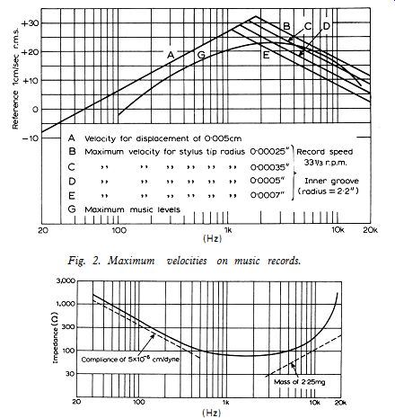
Fig. 2. Maximum velocities on music records.
Fig. 3. Maximum mechanical impedance required to track music records with maximum modulation, at a playing weight of 1.5g.
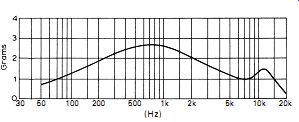
Fig. 4. Minimum playing weight for music levels with maximum modulation.
The lead zirconate crystals operating in flexure are supported at the rear end by a stiff block of plastic and an additional damping member is placed amidships, this also acts as the stylus cantilever support. The sections of the crystals are mutually perpendicular and 45° to the horizontal.
The analog is shown in Fig. 6. The cantilever stylus is driven from the record, and the mass M1 and compliance Cm1 are respectively the dynamic mass and the restoring force of the stylus itself. Normally the compliance between the stylus point and the compliant members driving the crystals is zero, therefore any shunt effect of motion to ground can be neglected. At the driving point the motion splits into two, and drives two identical crystal elements. Because the back support of the crystal is soft compared with the stiffness of the crystal as a whole there is appreciable motion over the whole of the crystal, and it is therefore more amenable to analysis if we split the crystal mass and put clamping impedances at the center and rear end of the crystal. The compliance and loss resistance at the crystal driving point is the compressional compliance of the coupling member between the stylus and the crystal, whilst the compliance and resistance at the remote end of the crystal is the clamping member. It will be seen that the series masses of coupling members will form resonant circuits which modify considerably the high-Frequency crosstalk-indeed because of the multiplicity of resonances analysis is approximate only.
Resistances represent the losses deliberately introduced into the system in order to make the steady state response of the cartridge as smooth as possible.
The force developed across the compliances of the crystal itself is converted into electrical energy by means of the transducer action, the e.m.f. being generated in series with the electrical capacitance of the crystal. It is the finite value of this capacitance which limits the output voltage at low frequencies when the cartridge is terminated in a practical value of resistance. The series mass between the cantilever and the crystal is the total mass of the coupling member. The other half of the circuit represents the load imposed at the driving point from the other crystal. Here, the reflected dynamic mass of the other channel coupling member is reduced because it is operated in flexure rather than in compression, whilst the compliance is very materially increased.
The low-frequency crosstalk separation is, to all intents and purposes, the ratio of these two compliances. Connected in parallel with this latter compliance is the complex impedance presented by the other crystal and its supports; it forms various resonant circuits at different frequencies and if the impedance at this point rises unduly it will be reflected in increased crosstalk.
During this analysis it is assumed that one channel only is being driven, but as both channels are symmetrical and identical, the analysis can be considered to be fairly rigorous. Because the cartridges are high impedance devices, a common ground connection can be used without introducing any substantial increase of crosstalk due to common ground impedance.
It will be appreciated from the foregoing that a rigorous analysis of this type of cartridge is very difficult, and it is usual to rely on "know- how" and empirical trial and error rather than to design the cartridge from basic piezo-electric and mechanical constants.
Compared with a single channel cartridge, it will be appreciated that the effective dynamic mass referred to the stylus must be greater than that of a single channel unit of the same crystal and stylus dimensions by virtue of the reflected impedances of the unwanted channel. Because the impedance is complex, the impedance changes rapidly with frequency, and is responsible for the wide variations in crosstalk, especially in the upper frequencies. Whilst, theoretically, the mechanical impedance of the twin channel cartridge should not be appreciably greater than that of the single channel (because of the de-coupling effect of the transmission members) in point of fact for a given sensitivity it is usually found that the mechanical impedance is about 50% greater than that of an equivalent single channel cartridge.
The external mechanical constants of this cartridge are compliance at 30 Hz, 5 × 10^-6 cm/dyne. Effective tip mass at 10 kHz, 7.5 milli- grams, playing weight 3 to 4 grams. Fig. 7 shows the response of this cartridge. It is not claimed to be high fidelity but gives an acceptable performance with domestic equipment.
As can be expected, the mechanical input impedance varies with frequency, as shown in Fig. 8. The rise at low frequencies is due almost entirely to the stiffness of the mounting and damping parts. The various drive members and supports are usually moulded from plasticized copolymers of vinyl chloride and acetate or other thermo-plastic material. The elastic constants of these plastics vary rather widely with temperature and both the output and compliance decrease with increasing temperature, as shown in Fig. 9. Be this as it may, about 90% of all twin channel cartridges presented to the public today are crystal or ceramic.
To summarize: A crystal cartridge has the prime advantages of low cost, ease of manufacture, and a high output voltage, which are precisely the requirements for transducers in the domestic reproducing field. To date, all crystal cartridges are of the 45-45 sensing variety, that is, the two elements are sensitive only to forces in the direction of their required plane, and no "sum and difference" crystal cartridges have yet appeared on the market.
Magnetic cartridges
Magnetic cartridge cartridges are fundamentally different from crystal in that the output voltage is proportional to the velocity of the armature and by inference to the velocity of the record groove modulation, whereas crystal devices produce a voltage which is proportional to the force applied to the crystal and, to a first approximation, to the amplitude of the modulated groove.
In order to achieve wide frequency response and low playing weight, the dynamic mass and the restoring force of the moving system must be minimal. At high frequencies of the order of l0kHz, accelerations in excess of 1000 g are experienced at high modulation levels, thus for playing weights of the order of 1.5 grams the maximum dynamic mass referred to the stylus point should be of the order of 1 milligram.
The majority of magnetic cartridges are of the moving magnet variety, although because of patent restrictions variable reluctance systems using the same mechanical configuration as that of the moving magnet (but using an external polarizing magnet) are now appearing on the market in increasing numbers. The overall design considerations and performance are approximately similar to those in the moving magnet design although it is possible in theory at least to reduce the mass moment of inertia (and hence the mechanical impedance at high frequencies) by substituting a thin walled tube in place of the solid rod used in moving magnet systems. The point of no return is quickly reached because of magnetic saturation of the subsequent very small cross-sectional area of the armature.
The magnetic circuit consists essentially of two pairs of pole pieces arranged symmetrically around the center line of the armature with cartridge coils wound over the yokes connecting opposite pairs of poles.
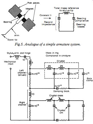
Fig. 5. Analog of a simple armature system.
Fig. 6. Analog of a crystal stereo cartridge.
The armature is usually a small cylindrical magnet about 0.030 inch diameter by 0.1 inch long cemented to a thin walled aluminum or dur-aluminum tube approximately 0.3 inch long and carrying a miniature diamond tip at the front end. The assembly is supported by a compliant hinge at its center of gravity and in some models a tie bar, usually 0.002 inch diameter stainless steel, is connected to prevent longitudinal motion. By suitable proportioning the dimensions of the tie bar it can also be used as the major restoring force, the plastic collar then providing central support and damping. The hinge can be one of a variety of elastomers, either copolymers of polyvinyl chloride or polyvinyl acetate; butyl plus neoprene rubber is sometimes used, as have been some of the polyurethanes. Silicone elastomers have not been very successful because of their low internal damping. The success (or failure)
of the cartridge is intimately bound up with this bearing design. The bearing is highly stressed in one direction due to the force developed by the playing weight-it is well known that most types of elastomers have a non-linear relation between stress and strain under these conditions. Additionally, hysteresis shows itself as distortion in the middle to high frequencies, At low frequencies the armature system vibrates about the center of the plastic bearing but it is very rare for the inertial center of gravity to coincide; the result of this is that with increasing frequency the effective mass increases, thus reducing tracking capabilities at high frequencies.
The static mass of this system is between 8 and 20 milli grams depending on the particular design and the dynamic mass at 10 kHz in the best designs can approach 1.2 to 2 milligrams. The static compliance varies between 5 × 10^-6 cm/dyne and, in extreme cases, 40 × 10^-6 cm/dyne, but because of the deliberately introduced mechanical damping (due to losses in the plastic hinge and sometimes by the addition of silicone or other grease) the mechanical impedance can be made almost wholly resistive between limits of 100Hz and 10kHz.
Clearance between the magnet and the poles is about 0.15 thou and because of the efficient magnetic circuit, generally using Mumetal or other high permeability materials, leakage flux is extremely low and from a magnetic point of view the system is extremely efficient. The sensitivity is generally of the order of 1 to 2 millivolts/cm/sec., although some recent Japanese cartridges have been produced with five times this output. The development of this elegant type of cartridge is due to Schmidt of Elac, Kiel, Germany, and has been extensively copied throughout the world.
Because of the magnetic symmetry, mutual induction between the coils is small and crosstalk arising from this factor is usually less than - 40dB whilst overall crosstalk varies between about - 10dB or - 15dB at the extremes of the frequency band (20 Hz and 20 kHz) improving to a maximum of about -30dB in the mid frequencies say, 500 Hz to 3 kHz. This crosstalk is due almost entirely to unwanted modes of vibration of the armature system. As an example, increasing the stylus length by only 0.01 inch can increase crosstalk caused by torsional vibrational modes by 15dB in the mid-upper frequency range. Not with- standing the technical criticisms, the performance of the best examples of moving magnet type cartridges are impressive.
The field strength (and hence sensitivity) of the variable magnetic field transducer, whether variable reluctance or moving magnet, is limited by saturation of the armature or the pole pieces and by the "negative compliance" due to the pull of the steady magnetic field on the armature. If the field exceeds a critical value determined by the static compliance of the armature restoring force it will result in the armature being attracted to one of the pole faces and hence no music! It is this negative compliance which generally limits the sensitivity of the cartridge, requiring coils of several thousand turns of fine gauge wire to produce a usable output.
Moving-coil cartridge
The moving-coil cartridge suffers none of the disadvantages listed above.
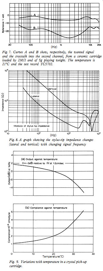
Fig. 7. Curves A and B show, respectively, the wanted signal and the
crosstalk into the second channel, from a ceramic cartridge loaded by
2M-ohm and of 5g playing weight. The temperature is 21°C and the test
record TC5702. (Hz)
Fig. 8. A graph showing the stylus-tip impedance changes (lateral and vertical) with changing signal frequency.
Fig. 9. Variations with temperature in a crystal pick-up cartridge.
If the magnetic field is linear and this condition is not difficult to achieve, the output will be strictly a function of coil velocity with no inherent generated distortion. Because of the absence of negative compliance the magnetic field can be increased to the limit and field strengths of the order of 15 kilogauss instead of a few tens or hundreds (Hz) of gauss are possible. In addition to increasing the output the signal to noise ratio is improved proportionately. The secret of success is in the design of the coil and the support system.
The most popular moving-coil cartridge uses a coil former in the form of a rectangular plate 2 mm square × 0.5 mm thick wound with four coils each with ten turns symmetrically placed about the center line.
Thus each generator consists of two coils in series; rising perpendicularly from the center plate is an aluminum tube cantilever about 7 mm long Temperature(°C)
Fig. 10. Diagrammatic representation of Toshiba C100P cartridge cartridge.
Fig. 11. frequency response curves for photo-electric cartridge. carrying the stylus at its free end. The rear end of the coil is flexibly mounted on to a steel tube which forms one pole of the magnet. The other pole in front of the coil is bored to take the cantilever and its protecting tube. The flexible mounting carries a damping block and is arranged to prevent fore and aft movement. There is, however, some torsional movement which shows as a minor resonance in the 7 kHz to 9 kHz region. The ratio of cantilever length to coil dimension is 7:1, giving a mechanical ratio of 50:1, and this results in an extremely low mechanical impedance at the stylus tip. Static compliance is of the order or 20 × 10^-6 cm/dyne, but because of mechanical damping the resistive component becomes pre-dominant between 100 Hz and 3 kHz, and approximates 40 mechanical ohms. Stylus resonance is at 26 kHz giving a calculated mass of 1.24 milli grams. The coils are low impedance, about 2 ohms, and a matching transformer is used to raise the voltage sensitivity to about 2 millivolts/cm/sec.
The best examples of the magnetic cartridges (both variable field and moving coil) described above can generally be produced to give a flat frequency response with velocity from 20 Hz to 10 kHz ± 1dB and 10 kHz to 20 kHz within ± 2dB. Crosstalk will generally approximate 25dB between 400 Hz and 5000 Hz, gradually deteriorating to 10dB or 15dB at the extremes of the frequency range. With lower priced units the frequency response is somewhat more variable, generally being characterized by a "suck out" of a few dB between 5 kHz and 15 kHz, the extreme high frequencies being restored by the stylus/record resonance.
"Strain Gauge" Cartridge
Recently a number of novel types of transducers have made their appearance, the first using a "strain gauge" transducer which unlike magnetic and piezo-electric cartridges is not a generator but operates by modulating a d.c. current supplied from an external source in sympathy with the mechanical information. The transducer proper is a tiny doped silicon element, 0.020 × 0.008 × 0.004 inch, similar to the base material of modern transistors. It is cemented to a plastic beam which in turn is driven through a flexible member by the stylus. For stereo use two such members are used, and the general assembly is very similar to that of the modern ceramic cartridge. The modus operandi of the transducer is that the resistance changes when subjected to a force across the driving points. The magnitude of the resistance change has a linear function of the applied force thus providing that the current through the element is constant the transducer is inherently distortion-less. The element is fed with a constant current and the resultant voltage which is proportional to displacement is applied to the amplifier through a coupling capacitor. Thus to a first approximation the response is similar to that of a crystal or ceramic cartridge.
The art in designing this type of cartridge is to so proportion the dimensions and the material of the drive back clamp and damping members as to give a mechanical transfer that is the inverse of the record amplitude characteristic, at the same time taking into account the fact that the mechanical impedance of the transducing element is several hundred times greater than the permissible stylus tip impedance.
The semiconductor transducer by virtue of its small size has a major advantage over the ceramic element in that resonances associated with it are outside the audio frequency spectrum (the average ceramic transducer has at least one major resonance in the mid-upper range) although resonances can and are introduced by other parts of the mechanical system.
The virtue of this type of cartridge is that because the transducer is a modulating element the electrical output power can be considerably greater than with "generating" types of transducer. Comparison between the high quality moving coil and this type of cartridge may be instructive. The moving coil cartridge requires a playing weight of 1.9 grams at a velocity of 20 cm/sec. at 1 kHz and produces an output of 800 millivolts from a source impedance of 2 ohms. Thus the input power is 2.7 milliwatts and the output power 0.32 milliwatts giving a conversion efficiency of 0.012 percent. A representative strain gauge cartridge requires a playing weight of 3 grams at a velocity of 20 cm/sec. at 1 kHz and gives an output of 120 millivolts from a source impedance of 400 ohms. Thus the input power is 4.2 milliwatts and the output power is 36 milliwatts and the overall efficiency is 1.16 percent.
Neglecting the electrical input power, the overall efficiency of this type of cartridge is approximately one hundred times as great as its ceramic counterpart! Distortion is commendably low, and signal to noise ratio more than adequate, but frequency response and crosstalk are inferior to the better magnetic units and because the response of the system is flat to d.c., motor rumble and low frequency feedback can be troublesome unless a rumble filter is fitted to the amplifier.
Photo-electric cartridge
During 1968 a new type of cartridge (or more correctly a new version of a pre-war type of cartridge) made its appearance, namely the photo-electronic cartridge. Fig. 10 shows a sketch of the system. The diamond stylus is placed at one end of an aluminum alloy tube 0.02 inch diameter × 0.25 inch long. The remote end of the tube supports a small flag--approximately 0.1 inch square × 0.002 inch thick. Pierced in this flag are two slots, 0.062 × 0.008 inch. The slots are mutually perpendicular and 45° to the horizontal. Behind the flag is a fixed screen with two similar slots and behind the screen are two photo transistors complete with miniature focusing lens each approximately 0.62 inch diameter. The moving assembly is supported by a compliant hinge approximately 0.040 inch in front of the flag under operating conditions the two pairs of slots overlap by 50%, displacing the stylus tip around this mean position will vary the amount of overlap and hence the total quantity of light received by the photo transistor and finally the output voltage developed by it. The lamp is fed from a stabilized d.c. power supply and the outputs from the photo transistors are taken through a correcting amplifier to the normal hi-fi amplifier.
Like the strain gauge and ceramic cartridges, this is a displacement type of cartridge in which the output is proportional to amplitude rather than to velocity. The frequency response is shown in Fig. 11, and it will be seen that the main resonance occurs at approximately 15 kHz, whilst at frequencies above 20 kHz the cartridge exhibits two resonant modes, one at 28 kHz in which the output drops to practically zero, and the other with a sharp peak at 35 kHz. These two resonances are probably connected with the dynamics of the light valve system.
Distortion at middle and low frequencies is quite low, being less than 1% at 2 kHz but increasing to 6% at 5 cm/sec. at 10 kHz.
This brief survey of currently available cartridges of necessity only skims the surface of technical development; considerable engineering skill is being constantly applied to the problems outlined above, and although the possibility of novel forms of transducer are remote, detailed improvements of established designs are continually appearing, thus automatically outdating any survey.
References:
1. United States Patent No. 1,520,378.
2. British Patent No. 394,325.
3. F. V. Hunt, J.A.E.S., Vol. 3, No. 1, pp. 2-18.
4. S. Kelly, Hi-Fi News, Vol. 2, pp. 339-342.
5. S. Kelly, Wireless World, June & July 1954.
(adapted from: Wireless World , Dec. 1969)
Also see:
Simple Class A Amplifier--A 10-watt design giving subjectively better results than class B transistor amplifiers.