The development of the electron tube and its associated communication circuits was not the work of any one scientist. Rather it was the cumulative result of the researches, discoveries, and inventions of numerous investigators. Actually, to trace the very beginnings of certain important discoveries, which later led to fruitful results, would necessitate a discussion beyond the scope of this guide. However, for all practical purposes, modern radio art may be said to have had its beginnings toward the end of the last century when, in 1883, Thomas A. Edison was experimenting with his newly invented incandescent lamp.
The Edison incandescent lamp may be regarded, in a sense, as the forerunner or prototype of the modern electron tube. Edison noticed that the carbon wire filament of these first incandescent lamps burned out at the point at which the filament entered the glass bulb. Looking for an explanation, he inserted a second conductor or plate into the lamp (this is basically the structure of the diode, or two-electrode tube of today), and recorded in his notebook that this dead end wire or plate, when connected through a current meter to the positive side of the battery, showed a flow of current ( FIG. 1) across the space between the filament and the plate. Normally, such an arrangement constituted an open circuit; therefore, current flow, according to the knowledge of electrical circuits at that time, was regarded as an impossibility, for here was an open circuit. Edison could find no satisfactory explanation for this phenomenon, which became known as the Edison effect.
An accurate and epoch-making explanation of the Edison effect was advanced in 1899 by a British scientist, Sir J. J. Thomson. He presented the theory that small, negative particles of electricity, called electrons, were emitted by the filament in Edison’s lamp as a result of operating it at incandescence or white heat. He said, further, that these electrons, because of their negative charge, were attracted to the positively charged plate. Thus, as long as the filament was heated to the proper temperature, electrons would flow from it to the plate. This movement of electrons constituted a flow of electron current, and the electron stream was the means by which the gap was bridged across the intervening space between the filament and the plate, thus closing the circuit.
Thomson’s findings came to be known as the electron theory. Briefly, this theory views the atoms of all matter as being composed of infinitesimally small, individual negative particles, or electrons, held within the atom by the attraction of a central nucleus of positively charged particles called protons. Under suitable conditions, as by the application of heat to a substance, some of the electrons within the substance could be liberated. This extremely important theory gave great impetus to subsequent research and led to great developments in electron tubes.
Equipped with this knowledge, other scientists explored further. The next significant development of far-reaching importance was the work of J. A. Fleming, an English scientists, who designed the first practical electron tube. Fleming observed from Edison’s work that when the plate connection was made to the negative rather than to the positive side of the battery, the current was zero ( FIG. 2). This property provided the basis for the operation of the electron tube as a rectifier; that is, as a device for the conversion of alternating current into direct current. Fleming, cal ling his modified version of Edison’s two-electrode lamp a valve (the term still used for the electron tube in England), thereby provided a superior detector to supplant the comparatively insensitive crystal detector.

FIG. 1. Circuit of Edison’s 2-electrode tube.

FIG. 2. With plate connected to negative side of battery, current through
tube is negligible.
Fleming’s valve was a two-electrode tube. For several years it was the only electron device in use. At this point it seemed that the progress of wireless communication had reached its practical limit, a limit determined by the existing methods and devices used for transmitting and receiving radio signals. The most powerful transmitters could transmit signals to receiving sets more than several hundred miles away, but the reception of such signals was undependable. The range and the dependability of radio communication could be increased only by the development of some method by which the weak signal could be amplified. A tube developed by Lee DeForest in 1907 supplied this needed means of amplification. Later improvements of this tube have made possible the reception of radio signals millions of times too weak to be audible without amplification.
DeForest, by inserting an extra electrode in the form of a few turns of fine wire between the filament and the plate of Fleming’s valve, made the tube an amplifier. DeForest called the third electrode the control grid. It provided the desired amplification by virtue of the fact that relatively large plate current and voltage changes could be controlled by small variations of control-grid voltage with out expenditure of appreciable power in the control circuit. De Forest called his three-electrode tube an audion, a designation superseded in present-day usage by the term triode ( FIG. 3).
TUBE TYPES
Each kind of electron tube is generally capable of performing many different functions, and therefore initial classification of these tubes is not based on functions, but upon their physical construction ( FIG. 4). The envelopes or housings are made of glass or metal or, in a few isolated cases, of both materials. The absence or presence of air or other gases in the envelope distinguishes the two fundamental classes of electron tubes. In the vacuum tube, all gases have been removed; in the gaseous tube, after all air has been removed, a small amount of mercury vapor or inert gas is placed within the envelope.

FIG. 3. Construction of DeForest’s 3-element tube, or triode.

FIG. 4. Representative electron tubes.
In all electron tubes, one electrode, called the cathode, is the emitter of electrons. The cathode must be heated to cherry red or to incandescence before the electrons are freed from its surface to move across to the second electrode, or anode. In vacuum tubes, sometimes called high-vacuum or hard-vacuum tubes, the cathode is in every case—except the photoelectric tube—heated by some external source of power, and these tubes, therefore, are not distinguished as to type of cathode. In gaseous tubes, sometimes called soft tubes, a further sub-classification is made into hot-cathode and cold-cathode types. In the first type, the cathode is heated to the proper temperature for emission by some external source of power; in the second type, the gas within the tube is ionized, and then the cathode is bombarded by positive ions which raise the cathode to the correct emission temperature.
Both vacuum tubes and gaseous tubes of either the hot- or cold-cathode type are further classified as to the number of active elements or electrodes contained inside the envelope. The simplest of these, described above, contains two elements and is known as a diode. A tube which contains three elements is known as a triode, and a tube with four elements is called a tetrode. If it contains five elements it is a pentode. In each instance, the type classification indicates the number of elements in the tube. In the following sections each of these tubes is illustrated and the differences between them fully explained.
Diodes
The simplest type of electron tube is the diode. It consists of two elements or electrodes, one of which is an emitter of electrons and the other a collector of electrons. Both elements are enclosed in an envelope of glass or metal. Although this discussion revolves around the vacuum diode from which most of the air has been removed, it should be understood that gaseous diodes also exist. The term diode refers to the number of elements within the tube envelope rather than to any specific application. In this connection, the complete electron-emitting system is treated as one element. Different names are applied to the diode to indicate the specific function of the tube in any particular electrical circuit. As one example, the diode can change alternating current into direct current; it is then a rec4fier, and the tube is named accordingly. Therefore, when discussing the basic diode, reference is made to the tube as a type, rather than to any of its applications.
The electron collector is called the plate and the electron emitter is called the cathode. Although the latter term more specifically applied to the indirectly heated type of emitter, whereas the directly heated type of emitter is referred to as the filament, the term cathode usually is used regardless of the method of heating. This usage is not so odd as it may seem, since the majority of tubes in use today are of the indirectly heated type.
In directly heated tubes, the filament is of the general construction illustrated in FIG. 5, showing two typical filamentary cathodes. The type shown at the left is known as an inverted V, and that on the right as an inverted W. The filament is held in place within the tube envelope (glass or metal) by means of suitable metal supports firmly resting in the glass stem of the tube. It is suspended from the top of the tube by a metal support which allows for the expansion of the filament wire when heated. The filament voltage is applied across the prong terminals of the filament in the tube base. FIG. 6 is a cross-sectional view of a simple diode tube, showing the internal construction, tube base and wiring.
In indirectly heated tubes, the cathode-heater design can be either of the two common types shown in FIG. 7. The heater wire is usually either U-shaped, as shown on the left in A, or it can be twisted throughout its length, as on the right in A. In indirectly heated tubes, the cathode is an oxide-coated cylindrical sleeve, usually of nickel, which enclosed the heater wire. The heater is insulated from the nickel sleeve by an Alundum coating on the heater wire or by passing the heater wire through fine parallel holes in an Alundum tube. In directly heated high-power tubes, the cathode heater is constructed of tungsten and thoriated tungsten, since high voltages tend to destroy oxide-coated cathodes.

FIG. 5. Directly heated filaments and schematic symbol.

FIG. 6. Cross-sectional view of simple half-wave diode of filament type.
The plate is usually of cylindrical construction, although frequently it has an elliptical form. Usually it surrounds its associated emitter, as in FIG. 6. The metals used for the diode plate (and the plates of most other tubes) usually are nickel, molybdenum, Monel Metal, or iron. A tube which contains one emitter and a single related plate is identified generally as a half-wave rectifier. Another name for tubes of this kind is simply diode.
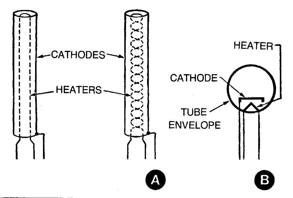
FIG. 7. Indirectly heated emitter and schematic symbol.
Triodes
The invention of the triode or three-element tube, was one of the most important steps in modern electronics. Up to 1907 the diode was the only electron tube used in the primitive wireless communication systems of that time. In that year Forest disclosed his third element, an electrode which was added to the diode and so formed the triode. Not only did it modify the diode, but it opened a new era in communication facilities. DeForest’s third element made present-day radio communication in all its forms a practical reality.
The emitter and the plate as used in the diode appear also in the triode. They retain their functions as a source of electrons and a collector of electrons, respectively. In the space between them, and located nearer to the emitter, is placed the third element, commonly called the control grid.
FIG. 8, illustrating the organization of the cathode, control-grid, and plate electrodes of the triodes, is an example of the oval-shaped form of grid, and shows how the grid surrounds the emitter on all sides. The plate electrode is seen enveloping the control grid. Other examples of triode construction exist, but they do not differ greatly from this.
The dimensions and the shape of the electrodes used in triodes as well as the physical spacing between the electrodes, differ in accordance with the intended uses of the tubes. Since these are related to such details as the values of plate voltage and plate current, the elements of triodes used in transmitters generally are larger than those used in receivers.
The internal structure of the triode seldom is completely visible through the envelope. When the envelope is made of metal the reason is obvious. When the envelope is made of glass the view of the inside usually is obscured because of the opaque coating formed by the getter when the tube is flashed—that is, heated to a high temperature. The getter is a substance that is placed within the envelope for the express purpose of absorbing any gases that may be liberated from the electrodes during initial operation. This keeps the vacuum created in the tube as high as possible. Magnesium is widely used as a getter, but other materials, such as barium, zirconium and phosphorous, also can be used.
The opaque deposit formed by the getter appears as a thin film on the lower half of the inside surface of the glass housing. The top usually remains transparent and some visual inspection of the electrodes inside is therefore possible. This is the usual means for determining whether the electron emitter is incandescent. In the larger transmitting tubes the getter coating usually does not obscure the metal parts inside the tube.
Tetrodes
Although the triode is an important device in communications, its use in amplifying systems is limited in some respects. The principal reason is the interelectrode capacitance between its electrodes, especially the capacitance between the control grid and the plate. As the frequency of operation is increased, the grid-plate capacitance affords an easier path for the transfer of energy back from the output to the input circuit. This action is most pronounced in a resonant system in which the grid and plate circuits are tuned to the same or similar frequencies. The result is that triode tubes seldom are used as amplifiers without recourse to special neutralizing systems to counterbalance the undesired feedback.
Neutralization is not wholly satisfactory. The higher the frequency of operation, the more critical is the adjustment. Sometimes it is impossible to neutralize properly over the entire band. Above all, neutralization is a critical adjustment and, frequently, a bother some one. Its use was reduced by the development of new tube types which obviate neutralization by greatly reducing the interelectric grip-plate capacitance as a feedback path.
In addition to the problems of feedback, the triode does not satisfy all the amplifying needs encountered in receivers, transmitters, and related apparatus. The physical relationship among the electrodes of the triode is such as to set unsatisfactory limits on the degree of amplification that can be achieved in a practical lube. At one time this posed a serious problem for design engineers because progress in communication depended on increasing the amplifying capabilities of equipment.

FIG. 8. Construction of triode, showing cathode, control-grid, and plate
arrangement.
The answer was found in two types of tubes. Both are based on the triode but represent modifications of the original three-element electron tube. One of the versions is the tetrode or four-electrode electron tube, which contains an electron emitter, two grids, and a plate. The other is the pentode, which contains five electrodes, an electron emitter, three grids and a plate.
The development of electron tubes since the early 1920’s resulted in more than just the multi-electrode tetrode and pentode. Other tubes which have been developed are various combinations of diodes, triodes, tetrodes and pentodes in the same envelope. These are identified by the general name of multiunit tubes.
The four-electrode tube contains all the electrodes of the triode (with generally similar functions) and, in addition, a fourth electrode. This is the screen end. As a rule, the four-electrode tube is called a tetrode, although upon occasion it is referred to as a screen-grid tube.
The physical organization of the tetrode ( FIG. 9) does not differ too much from that of the triode. In A, the screen grid of the tetrode (type 48) is rectangular in shape. The plate is fine-shaped for heat dissipation purposes. In B, the outer screen grid is a perforated-metal structure of circular shape (type 32), located between the glass envelope and the plate electrode. The inner screen grid is oval and is located between the control grid and plate. There is variation in the shape of the grids; in some instances a helical form is used. The functioning of the electrodes is fundamentally the same regardless of the shape.
C and D show external views of two tetrodes. The tubes are substantially alike in appearance, but differ in one respect. The practice of using pins in the tube base as connecting points to the electrodes inside the envelope is followed in the tetrode, but an exception is the use of a metal connecting cap on the top of the tube. Tubes which have electrodes connected to portions of the envelope in addition to the base are called double-ended tubes. If all the electrodes appear as pins or prongs in the base of the tube, they are called single-ended tubes. In some tetrodes designed for use in receivers and similar low-power equipment, the cap illustrated in C affords electrical connection to the control grid. The plate, screen- grid and heater (or filament) junctions are made through the tube base pins. In some higher-power tubes, such as are used in transmitters, the cap furnishes electrical contact with the plate electrode, as in D. The remaining tube electrodes terminate at the base pins. The reason for cap connections to the control grid or to the plate, as the case may be, is the desire to reduce the capacitance between the connecting pin terminations of the control grid and the plate.
It is common practice to use the full names, such as control grid and screen grid, but for tube schematics it is advantageous to designate these electrodes in abbreviated form as G1 and G2. The smaller number is assigned to the grid which is closer to the cathode, this being the control grid. Therefore, G2 represents the screen grid. These notations are included in two schematic representations ( FIG. 10). The old tube symbol, in A, finds little use in modern literature. B shows the modern tube symbol. It also is interesting to note that abridgement of the words screen grid to the single word screen, as meaning the same thing, is practiced regularly. When illustrated schematically with operating voltages applied to all the electrodes, the tetrode appears as in FIG. 11. The main difference between the tetrode and the triode is the screen circuit and the source of its operating voltage. In normal use, the screen is made positive relative to the cathode by receiving a voltage from source Ebb, which also supplies the plate voltage. In the majority of in stances, the DC screen voltage is appreciably less than the DC plate voltage.

FIG. 9. Physical construction of tetrodes.

FIG. 10. Tube symbols for tetrode.
Pentodes
The pentode is a five-electrode electron tube. It contains an emitter, three grids and a plate. The grid closest to the cathode, G1, is the control grid; next is the screen grid, G2; and the third, located between the screen grid and the plate, is the new suppressor grid, G3. The construction of a metal-type pentode is shown in FIG. 12. Symbolized, the pentode is shown in FIG. 13.
Functionally speaking, the action of the emitter, control grid, screen grid and plate in the pentode are the same as in the tetrode except that, whereas the tetrode suffers from negative-resistance effects, the pentode is free from these because of the action of the suppressor grid.
In external appearance some pentodes resemble the tetrode. This similarity is so great, even to the use of control-grid, or plate caps on the top of the tube envelope, that identification by visual inspection is difficult. Three receiving-type pentodes are shown in FIG. 14. The envelope of a pentode may be glass, as in A, or metal. A departure from the tetrode appearance is the acorn-type tube shown in B. This is a comparatively small tube requiring a special socket and having wire extensions serving as the tube pins. Another physical feature of the acorn pentode is the location of the plate connection at the top and the control-grid connection at the bottom of the envelope. These are stiff wires which protrude through the envelope. Another type of miniature tube is shown in C.
Multi-grid Tubes
Tubes which have more than three grids commonly are referred to as multigrid tubes. For instance, if a grid is added to a pentode, a six-electric multigrid tube results. This tube is known as a hexode. The schematic symbol for an indirectly heated hexode is shown in A of FIG. 15. Other multigrid tubes are the heptode, shown in B, which contains five grids, and the octode, in C, which has six grids. In these tubes, as in the basic types, the grids are designated in numerical order starting with the control grid, as shown.
The hexode is an experimental tube and is never manufactured commercially. Heptodes, also known as pentagrid tubes because of their five grids, are used mostly in frequency converter or mixer circuits. When a heptode is used as a frequency converter, two voltages having different frequencies are each impressed on a separate grid of the tube. Heptodes also are used as volume compressors and expanders. In these applications the gain of an amplifier is controlled automatically. Just as the heptode, the octode also is used as a frequency converter.
Multiunit or Dual-Purpose Tubes
A multiunit or dual-purpose tube is one in which two or more individual tube-element structures are combined within a single envelope. As a result, compactness, economy and more satisfactory operation for certain purposes are achieved. The most commonly used multiunit tubes, known as duo-diodes and duo-triodes, combine two diode or two triode elements. Frequently, a single common cathode is used which supplies electrons to both sets of elements in the multiunit tube. Occasionally, an electrode of one set of elements is connected internally to an electrode of another set of elements.

FIG. 11. Circuit representation of tetrode.
 FIG. 12. Physical Construction of pentode.
There are many types of multiunit tubes, used for a wide variety of purposes. The schematic symbols of the most common ones are shown in FIG. 16. The tube whose symbol is shown in A can be used as a full-wave rectifier, an FM (frequency-modulated) discriminator, or a combination detector and AVC (automatic volume control) rectifier. The diode-triode, in B, can be used as a diode detector and a triode amplifier. The duo-triode, in E, is used as a push-pull amplifier, two amplifiers in cascade, or as a special type of complex-wave generator. The triode-hexode, in L, and the triode heptode, in M, are used as mixer-oscillators superheterodyne receivers.
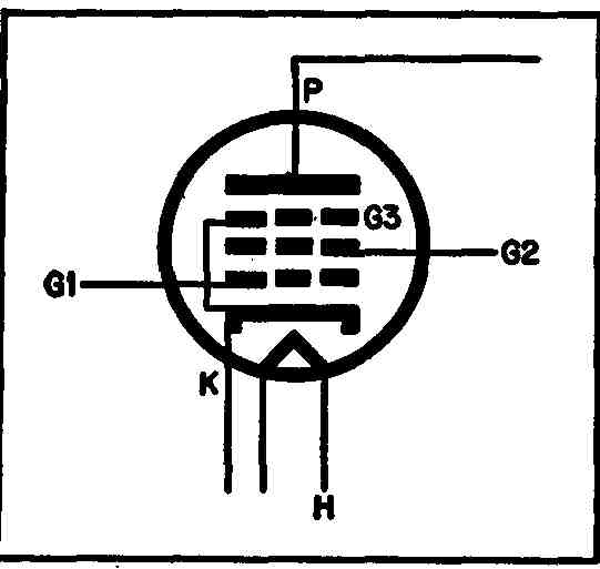
FIG. 13. Symbol of pentode.

TBL. 1. Examples of multipurpose tubes in receivers.
TBL. 1 lists typical examples of multipurpose tubes to be found in receiving-type
equipment. The letters in the first column refer to the symbols used in FIG.
16.

FIG. 14. Different types of receiving pentodes.

FIG. 15. Schematic symbols of multigrid tubes.

FIG. 16. Tube symbols for multiunit tubes.
Magic Tuning Eye
Electron-ray indicators ( FIG. 19) are widely used in radio receivers to indicate proper tuning. Most indicator, or magic eye, tubes contain two sets of elements, one of which is a triode amplifier. The other section is a cathode-ray indicator.
The electrons emitted by the cathode strike the conical plate, or target. This target is coated with a fluorescent paint that glows under the impact of the electrons. A small wire electrode called the ray-control electrode is parallel and dose to the cathode. It deflects some of the electrons emitted from the cathode, producing a shadow on the target. This shadow is wedge-shaped, and the angle of the wedge varies with the voltage on the ray-control electrode. The plate of the internal triode amplifier is connected to the ray-control electrode, and therefore the shadow angle varies with the negative voltage applied to the grid of this triode. When the ray-control electrode is at the same potential as the target, the shadow closes completely. If the ray-control electrode is less positive than the plate, a shadow appears which is proportional in size to the difference in voltage. Since the voltage on the electrode is the same as that of the internal triode plate, the shadow angle increases with a more positive grid voltage.
SOCKETS FOR TUBES
The various types of electron tubes just discussed all must have some means of applying potentials and making connections to the various electrodes within the envelope. The external leads take the form of tube prongs, pins or caps. Usually, a group of prongs or pins is built into a tube base. The base material often is Bakelite, although other insulating materials are used. Sometimes the connecting leads take the form of pins which are built into the tube envelope itself. Occasionally, metal caps are bonded to the tube envelope, and the tube electrodes are connected to these caps through the envelope. The specific method used depends on the particular tube involved.
The early triode receiving tubes used a four-prong base. Two of these prongs were connected internally to the filament, and the other two were connected to the grid and the plate. The two filament prongs were slightly larger in diameter than the other prongs, so that the tube could be inserted properly in a corresponding four-hole socket. It is necessary to insert the tube properly so that the proper operating voltages can be applied to the correct electrodes. Unless some such method is used to key the tube, it can be damaged by improper placement in its socket. Other methods have been used to key the four-pin base. One method involves the use of a small metal projection on the tube base which permits the tube to be inserted in its socket in only one manner. Another method is to arrange the base pins in such a pattern that the tube can be inserted into its socket in only one way.
With the advent of more complex tubes, it became necessary to add more connecting pins to the tube base. The five, six, seven, eight and nine-pin bases were introduced. All of these bases are keyed by means of special fittings on the tube base which permit the tube to be inserted in the socket only one way ( FIG. 17).
One of the most widely used of these multipin bases for receiving tubes is the eight-pin or octal base. In this base all the pins have the same diameter, and they are spaced. However, at the center of the base is an insulating post which has a vertical ridge. This acts as a key or guide pin which fits in a keyway in the tube socket. Thus, the tube can be inserted in only one way. The original idea of the octal socket was to have similar electrodes of any type of tube connected to the same pins, so that some degree of standardization would result. If any of the pins are not used they are left off the base, or no connection is made to them.
A variation of the octal base is used with lock-in receiving tubes. The base of such tubes also has eight pins. However, the contact pins are sealed directly into the glass envelope and no insulating base is used. The bottom portion of the envelope is fitted with a metal shell and a metal key or guide pin. This guide pin has a vertical ridge like the one used in the octal base. A groove around the bottom of the locating pin fits into a spring catch in the socket. This holds the tube firmly in the socket.
Another variation in the base of receiving tubes is used with miniature glass tubes. These tubes are used in modem electronic equipment because of their small size and many other desirable characteristics. Contact pins of these tubes are sealed directly into the glass envelope. Either seven or nine pins generally are used. Because of the additional spacing between two of these pins, the tubes cannot be inserted improperly in their sockets. FIG. 18 illustrates six different types of electron-tube bases and their corresponding sockets.
Transmitting and special-purpose tubes use sockets and methods of connection which are subject to considerable variation. Some small transmitting tubes use a base structure similar to that used for receiving tubes. However, the larger types use special connections and terminals which are not at all standardized. Special high-frequency tubes use connection methods which conform with their special requirements. Cathode-ray tubes may use conventional octal sockets or sockets which have more than eight pins. A few commonly used bases for these tubes are the magnal (eleven-pin), duaodecal (twelve-pin), and the diphetal (fourteen-pin).
A standard system has been set up for numbering the base pins of the common tube bases. The pins are numbered consecutively in a clockwise direction looking up at the bottom of the tube base. When fewer than eight pins are required, the unnecessary ones are omit ted and the spacing and the numbering of the remaining pins are unchanged. In the octal and lock-in-types, pin 1 is the pin directly clockwise of the ridge on the guide pin, as in FIG. 17. In the miniature types, pin 1 is the clockwise pin of the two widely spaced pins. Other designations are shown in the figure.
Some attempts at electrode connection standardization were made by electron-tube manufacturers. These were only partly successful, because of the tremendous variety of tubes manufactured. A good many receiving tubes, however, do show a degree of uniformity in pin connections worth noting. For example, in the four-pin base, pins 1 and 4 usually are connected to the filament, pin 2 is connected to the plate, and pin 3 is connected to the control grid. In the five-pin base, pins 1 and 5 frequently are connected to the heater, pin 2 is connected to the plate, pin 3 is connected to the control grid, and pin 4 is connected to the cathode. When a five-pin base is used for a pentode tube, it is common practice to make the same connection as above except that the screen grid is connected to pin 3, and the control grid is connected to a grid cap at the top of the tube. The suppressor grid is connected internally to the cathode. In the six and seven-pin bases, pins 1 and 6 and pins 1 and 7 frequency are used as the heater connections. In the octal base, pin 1 usually is connected to the metal envelope or internal shield, pins 2 and 7 are connected to the heater, pin 3 is connected to the plate, pin 4 is connected to the screen grid, pin 5 is connected to the control grid, and pin 8 is connected to the cathode and the suppressor grid.

FIG. 17. Common electron-tube bases, showing arrangement of pins.
In the lock-in tube base, pins 1 and 8 usually are the heater connections. It must be emphasized that the wide variety of tube types makes it impossible to adhere rigidly to these pin connections.
HOW TUBES ARE NUMBERED
Every electron tube is identified by a number or a combination of numbers and letters. In 1933 a systematic method of designation was developed. So many different types have been introduced since that time that it has become impossible to always stick to the system that was set up.
The type number of a tube is divided into four parts. First, a number consisting of one or more digits designates the filament or heater voltage. Second, one or more letters designate the type or function of the tube. Third, a number designates the number of useful elements in the tube. Fourth, one or more letters designate the size or construction. For example, the type 2A3 is a power triode which requires a filament voltage of about 2 volts (actually 2.5 volts). It is an amplifier tube and has three useful elements. The fourth part of the designation is omitted. The type 5Y3-G is a duo-diode which requires a filament voltage of 5 volts; it is a rectifier (letters from U to Z are used for rectifiers) and has three useful elements. The letter G indicates that the tube has a glass envelope. The type 50L6-GT requires a heater voltage of 50 volts, is a beam power amplifier (the letter L is used for such tubes) and has six useful elements if the heater and cathode are considered separately. The letters GT indicate the use of a glass envelope somewhat smaller than the conventional size.
Because of the thousands of different types of receiving tubes that have been manufactured, there are probably more exceptions to this system of designation than there are tubes which follow it completely.
For an explanation of the standard system for numbering base pins, refer to Sockets for Tubes in this Section.
DATA AND USES OF THE TUBE MANUAL
Manufacturers of electron tubes have available listings of their particular tubes with the characteristics and technical descriptions. Several such publications do exist, known as tube manuals. The largest tube manuals (RCA, GE), which include several hundred pages or more, list only receiving-type electron tubes. When tube manual is referred to in this Section, we mean the receiving tube manual. The Section includes an excerpt from the 1948 RCA Receiving Tube Manual. This old edition, of course, is no longer in print.
Although no two of these tube manuals are identical, they all contain more or less the same type of information. Some older manuals were so designed that pages describing new tube types could be inserted to keep the guides up-to-date. Now manuals are revised and reprinted from time to time.
The tubes are listed according to the numerical-alphabetical sequence of their type designations. The schematic symbol of each tube, showing the base-pin connections to the various electrodes, is given. A brief description of the tube is included in some manuals as an introduction to the tube characteristics. Next, the physical specifications are designated. These include information concerning the dimensions of the envelope, the type of base and sometimes the preferred mounting position.
Following the physical specification, the electrical ratings are given. These include information regarding the filament or heater voltage and current, as well as the maximum electrical ratings of the tube. Maximum plate and screen voltages, maximum plate and screen dissipations, and peak heater-to-cathode voltage are in eluded. In addition, the interelectrode capacitances of some types are listed. If the tube has other modes of operation—for example, a pentode operated as a triode or a pentode operated in push-pull— additional ratings and electrical specifications frequently are given.
 FIG. 18. Receiving-type electron-tube bases and corresponding sockets.
Next, typical operation of the tube is shown. Figures for the following are often included: typical electrode voltages, required value of cathode bias resistor, peak signal voltage, typical electrode currents under conditions of zero and maximum signal, required value of load resistance, power output and total harmonic distortion. In addition, values of amplification factor, transconductance and plate resistance are supplied. If the tube commonly is operated under different conditions, a complete set of typical operating values frequently is included. For example, in one tube manual, maximum ratings and typical operating values are given for the 6L6 (beam power amplifier) under the following operating conditions: single- tube class A amplifier, single-tube class A amplifier (triode connected), push-pull class A amplifier, push-pull class AB1 amplifier, and push-pull class AB2 amplifier. Ratings also are given for most of the foregoing, using fixed bias or cathode bias.
Following the typical operating values is a section dealing with specific applications. Special installation notes having to do with the particular tube type also may be supplied, and unusual features of the tube are discussed.
Finally, one or more families of curves depicting the operation of the tubes are shown. Usually, these curves are the average plate characteristics for various values of grid voltage. Sometimes, one or more load lines are drawn on the characteristic curves. In some tube manuals, average transfer characteristic curves are shown, along with curves that illustrate the variation in plate resistance, transconductance and amplification factor at various electrode voltages.
If the particular tube listed happens to be a rectifier, ratings or curves are given which apply to use of the tube. The maximum peak inverse plate voltage and the maximum peak plate current are given, as well as the voltage drop across the tube at certain values of plate current. The output current for various AC input voltages and types of filter circuits is designated. Curves frequently are shown which give the DC output voltage and load current for various input voltages and filter circuits.

FIG. 19. Cutaway view of 6E5 electron-ray indicator.
Many tube manuals supply additional information. A section dealing with general tube and circuit theory may be included. Some times the common tubes are classified as to their use and characteristics. Frequently, a section of the tube manual is devoted to the design of resistance-coupled voltage amplifiers. This section usually consists of tables for the commonly used amplifier tubes. The tables include information concerning the proper combination of plate load resistor, grid resistor, screen-grid resistor, cathode-bias resistor, and coupling and bypass capacitors for various values of plate-supply voltage. The output voltage, voltage gain and sometimes the percentage of distortion are also included under the various conditions outlined in the table.
Finally, the tube manual may contain circuit diagrams which illustrate some of the more important applications of the tubes listed in the manual. Some manuals provide information on obsolete or seldom encountered types, as well as on panel and ballast lamp specifications.
The tube manual provides a listing of the characteristics and socket connections of the electron tube. In servicing electronic equipment, it frequently is necessary to trace circuits, check components connected to various electrodes of tubes and measure tube electrode voltages. Because of the wide variety of electron tubes used in receivers and because of the general lack of standard base connections, it is often necessary to refer to a tube manual for socket connections. Remember that all views of tube bases or sockets are bottom views, unless otherwise indicated.
The normal operating voltages shown in the manual serve as a guide for servicing. You can compare the operating voltages given for a particular tube in the manual with the voltages measured in the equipment. If an electron tube is used for a special application, the operating voltages may not be similar to those shown in the manual. However, the measured voltages should not exceed the maximum ratings given and the filament or heater voltage should certainly correspond to the value designated in the manual.
The average plate characteristic curves have several uses. They show the operating conditions of the tube with various electrode potentials. These can be used to compare the actual operation of a tube in a circuit with the proper average operation. In addition, the curves serve as a basis for many useful calculations. A load line is constructed on the family of curves for the particular value of plate load used. By means of this load line and the curves shown in the manual, the power output and the percentage of distortion can be determined. These are determined by direct graphical methods; that is, actual values are read from the curves and these values are substituted in simple equation which show the power output and distortion. The curves are also used for design purposes. A given set of electrode potentials is assumed, a load line is drawn and calculations are based on the curves. These calculations show whether the plate dissipation of the tube is exceeded, and whether the power output and the fidelity are adequate. The transfer characteristic curve can be used to determine the operating range for tubes used for detection or for AVC action. Conversion characteristic curves are used in the design of converter stages, and diode load curves are useful in designing electron-tube voltmeters or AVC systems.
The tube manual permits a comparison between tubes. Comparative characteristics of several beam-power tubes, for example, can be examined to determine which tube fits the specific application required. In addition, physical dimensions of tubes can be found. This information is important in the mechanical design and construction of a piece of electronic equipment.
The section of the manual dealing with the design of resistance-coupled amplifiers gives specific component values that can be used to achieve certain results.
In addition to the preceding, some tube manuals contain an excellent section on theory and application of electron tubes. Illustrations frequently are included to show the internal construction of various types of receiving tubes.
ORIGIN OF RECEIVER INPUT
The purpose of a receiver is to convert the electromagnetic wave, from the transmitter, into energy usable by the human ear. Before entering into a discussion of the manner in which the receiver accomplishes this, you might find a brief review of the origination of the transmitted wave advantageous. FIG. 20 illustrates the block diagram of a basic transmitter and the nature of the input and output energy of each section.
The input to the transmitter is in the form of sound waves, which are produced by voice, musical instruments, etc. These sound waves range in frequency from about 20 cycles per second (hertz) to about 20,000 cycles per second. The microphone converts the sound waves into an electrical signal which varies in frequency and amplitude in accordance with the original sound. Because the electrical signals from the microphone are very weak, they are fed to the modulating section (audio amplifier), which increases the amplitude to a level suitable as an input to the power amplifier.
In the RF unit, the power amplifier has two inputs. One input is the audio signal from the modulator, and the other is the constant amplitude radio frequency signal from the oscillator. In the broadcast band, the channel frequencies for various transmitters will range from 535 kHz to 1605 kHz. The output of the oscillator is called the corner frequency. In the power amplifier, the audio signal (intelligence) is impressed on the carrier. The output of the power amplifier is a modulated RF signal, which is then fed to the antenna.
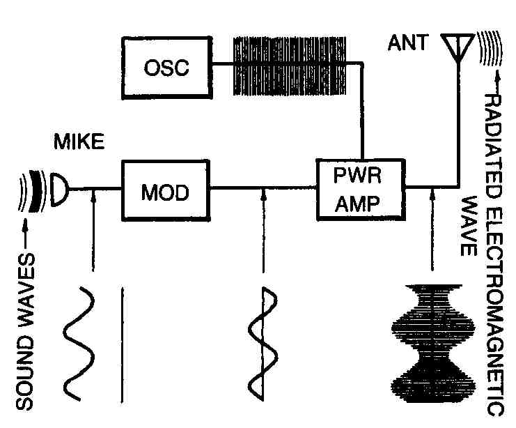
FIG. 20. Basic transmitter.
The antenna radiates the modulated RF signal in the form of electromagnetic waves. This electromagnetic wave will now be used as the input to the receiver.
FUNCTIONS OF A RECEIVER
A receiver must perform certain basic functions in order to be useful. In order of their performance, these functions are reception, selection, detection, AF amplification and reproduction.
Reception involves having the transmitted electromagnetic wave pass through the receive antenna in such a manner as to induce a voltage in the antenna.
Selection involves being able to select a particular station’s frequency from all the transmitted signals that happen to be induced in the receiving antenna at a given time.
Detection is the action of separating the low-frequency intelligence from the high-frequency carrier.
The AF amplification involves amplifying the low-frequency intelligence (audio in the case of a radio) to the level required for operation of the reproducer.
Reproduction is the action of converting the electrical signals to sound waves which can then be interpreted by the ear as speech, music, or whatever.
The ability of a receiver to reproduce the signal of a very weak station is a function of the sensitivity of the receiver. In other words, the weaker a signal that can be applied to a receiver to still achieve the same value of signal output, the better is the sensitivity rating of that receiver.
The ability of a receiver to select and reproduce a desired signal from among several closely spaced stations, or from among interfering frequencies, is determined by the selectivity of the receiver. In other words, the better a receiver is at differentiating between desired and undesired signals, the better is the selectivity rating of the receiver.
FIG. 21 shows the block diagram of a simple receiver that will perform all the functions required of a receiver. Also illustrated are the functions performed by the various sections of the receiver. The input to the receiver is the electromagnetic wave propagated from the antenna of the transmitter. This wave will pass through the antenna of the receiver and induce a small ac voltage. The section of the receiver formed by the antenna and L1, perform the function of reception. L1 is the primary of the input transformer, and the voltage induced in L1 is coupled to the secondary, L2. L2 and C1 form a tuned circuit with C1 being variable to permit tuning across the broadcast band. Thus, the tuned input circuit performs the function of selecting a specific frequency from among those present in the antenna circuit. The output of the tuned circuit is a modulated RF signal.

FIG. 21. Simple receiver block diagram.
This modulated RF signal is then fed to the detector circuit where the function of detection (rectification and filtering) is performed. The output of the detector circuit is a weak audio signal. The audio signal from the detector is too weak to satisfactorily operate a speaker; therefore, it is fed to an audio frequency amplifier to increase its amplitude. The output of the AF amplifier is fed to the speaker, which performs the function of reproduction—converting the electrical signals back to the form of the original input to the transmitter. (In this case, we’re referring to sound waves).
DIODE DETECTOR
The first widely used receiver, the crystal set of fond memory, was exceeding simple, yet it had all of the functions depicted in FIG. 21 save amplification. Its circuit diagram is shown in FIG. 22. There’s something strangely fascinating and appealing about a de vice that is so simple and yet can pull sounds out of the air that originated many miles away.
The crystal detector was invented in 1906 by two Americans, H.H. Dunwoody and G.W. Pickard. The crystal was a hunk of quartz or galena. One connection was made to the base of the crystal, the other crystal connection was made to a sensitive spot—which one found by trial and error—by means of a short and very fine wire, which was called a cat’s whisker.
Up until about 1920, most radio receivers were homemade crystal sets. Crystal sets were manufactured as home entertainment instruments for several years thereafter. In 1922, such a set sold for about $25. Eventually they were replaced in the home-entertainment market by tube-type radios, but they were made as toys for quite a number of years longer. In fact, the construction of crystal sets is still an attractive divertissement for experimenters.
The function of a radio receiver is to intercept a small percentage of the radio-wave energy radiated from the antennas of transmitters and recover the original intelligence contained in it.
The transmitter of a radio station may have an output power on the order of thousands of watts, and the voltage on the transmitting antenna may be on the order of thousands of volts. However, the value of RF energy intercepted by the receiver depends on many factors: the distance between the transmitter and the receiver, the location of the receiver (in a valley, on a hill, behind a building, etc.), the type of receiving antenna used (directional, high gain, etc.), orientation of the receiver antenna, the power of the transmitter, and the type of terrain over which the signal passes on its way to the receiver. Therefore, after taking all of these factors into consideration, it is not surprising to find that usually the receiving antenna intercepts only a few microwatts of power, and the voltage induced in the antenna is measured in microvolts.
In FIG. 22 the antenna performs the function of reception. Selection of the desired signal is accomplished by adjusting the variable tuning coil, L1. The crystal detector (CR1) rectifies the signal, and the capacitor (C1) filters the RF component of the detected signal. The audio component of the signal is then passed on to the earphones, which perform the function of reproduction by converting the electrical signal into sound waves. Later, the crystal was sometimes replaced by a vacuum-tube diode.

FIG. 22. Crystal set schematic.
It was difficult for a family to enjoy a radio broadcast when only one person at a time could use the earphones. This problem led, by popular demand, to another function being added to the receiver— audio amplification. Now the set produced enough power to operate a speaker, and everybody could hear the reproduced sound waves at the same time. Reception was still difficult, and as the broadcast spectrum began to fill up with stations, it became increasingly more difficult to separate one station from the other. It was discovered that the addition of RF amplifier stages not only increased the sensitivity of the set (allowed reception of weaker stations), but also its selectivity (allowed better discrimination between adjacent stations).
In the search for improved reception, engineers added 3,4 and sometimes 6 stages of tuned radio frequency amplification to the receivers. This led to increased problems in tuning and neutralization.
Many of the problems of the trf receivers were reduced or eliminated by the introduction of the superheterodyne principle of reception, and today practically all radio receivers use this principle. The tuned RF amplifier is not necessary to the operation of a superheterodyne receiver, but one or more RF amplifiers are included in higher quality receivers where better reception is desired.
All electron tubes have the characteristic of unilateral conductivity. Consequently, any one of them can serve as a rectifying device. Combined with a filter, a triode—for example—can serve as a detector in the same manner as the diode detector.
Having no grid, a diode cannot amplify a signal. As a matter of fact, the output taken from a diode stage is less than its input. This disadvantage is overcome by using a tube with a grid, such as a triode or pentode. The signal is not only detected, but is also amplified in one stage. In early receivers, this arrangement was necessary because of the lack of RF amplification. As much gain as possible had to be achieved.
The operation of the grid-leak triode detector ( FIG. 23) is as follows: the signal voltage applied to the grid of the triode tube is alternately positive and negative; grid current flows during the half cycles in which the grid is positive with relation to the cathode; during the negative half cycles, no grid current flows; as a result, a unidirectional pulsating direct current flows through Rg. Capacitor Cg serves as a filter to smooth the RF pulses. A DC voltage is produced across Rg, and this voltage varies at an audio rate just as in the case of the diode detector.
The AF voltage across the grid resistor now can be used as a signal voltage for the triode amplifier. As a result, an amplified AF signal appears in the plate circuit of the grid-lead detector. Capacitor C is an additional RF filter.
The grid-leak detector operates as a square-law device. A square-law detector is one whose AF output voltage varies as the square of the RF input voltage. In the diode detector, by comparison, the output varies directly with the input.
The development of higher-gain RF amplifiers led to the re placement of the grid-lead detector by the half-wave diode detector. The diode detector distorts the AF signal much less than the grid-leak detector.
In 1912, the American inventor Edward Howard Armstrong conceived the notion of taking part of the RF output of the triode and feeding it back to the input for further amplification. The enhanced input, in turn resulted in a much stronger output than was obtainable with an ordinary triode detector. Because of its simplicity, sensitivity and selectivity, the feedback or regenerative detector of Armstrong was popular with experimenters for many years. When radio manufacturing began in earnest in about 1920, the regenerative circuit was at the height of its popularity. A few years later, it was succeeded as the sensation of the radio world by the neutrodyne receiver. In 1922, a one-tube regenerative set sold for about $80.
The regenerative circuit is mainly of historic interest. It is little used anymore, though it is still the most sensitive circuit possible with a triode. The regenerative detector was the first important use of the triode. Between the invention of the triode by DeForest in 1906 and the invention of the feedback circuit in 1912, the application of the triode had been in limbo. Some non-feedback triode detectors had been built, but they offered little improvement over other detectors. The regenerative principle was later to prove important to transmitters as well as receivers. In fact, the regenerative oscillator is the basis of the transmitters used today.
When high sensitivity and selectivity are the most important factors to be considered, a regenerative detector may be used. However, the linearity as well as the ability to handle strong signals without overloading is very poor.
A grid-leak detector may be modified to operate as a regenerative detector, as indicated in FIG. 24. Because an amplified RF component is present in the plate circuit of the grid-leak detector, regeneration can be obtained by connecting a coil (L2), known as a tickler coil, in series with the plate circuit so that it is inductively coupled to the grid coil (L3).
With an RF signal across L3, an RF component of plate current flows through L2. L2 is connected so that the voltage it induces in L3 is in phase with the incoming signal voltage applied to the grid. Thus, the voltage gain of the stage is increased.
It is important that the voltage fed back by the tickler coil be in phase with the incoming signal voltage. Otherwise the feedback will be degenerative and the amplification will be reduced. Furthermore, if the coupling between L2 and L3 is too great, oscillation will take place. For receiving code signals, oscillation is desirable in order to produce an audible beat tone. However, it is not desirable for voice or music reception because of the objectionable squeal from the beat tone. The regenerative detector is the most sensitive triode detector circuit possible when it is operated just below the point of oscillation.

FIG. 23. Circuit of grid-leak detector.

FIG. 24. Regenerative detector.
TRF RECEIVER
The tuned radio frequency receiver, generally known as the trf receiver, consists of one or more RF stages, a detector stage, one or more trf stages, a reproducer and the necessary power supply. A block diagram of a trf receiver is shown in FIG. 25. The waveforms that appear in the respective sections of the receiver are shown above the block diagram.
The amplitude of the AM signal at the input of the receiver is relatively small because it has been attenuated in the space between the transmitter and the receiver. It is composed of the carrier frequency and two sideband frequencies. The RF amplifier stages amplify the waveform, but they do not change its basic shape if the circuits are operating properly. The detector rectifies and removes the RF component of the signal. The output of the detector is a weak signal made up only of the modulation component, of the incoming signal. The AF amplifier stages following the detector increase the amplitude of the AF signal to a value sufficient to operate the loudspeaker or earphones.
The plain trf receiver was popular with experimenters in the early days, and with manufacturers throughout the 1920s. It was gradually replaced by the neutrodyne and superheterodyne circuits. One of the problems with trf receivers was a tendency of the RF stages to break into oscillation when operated at high gain. As in g Armstrong’s detector, the regeneration was intentional and controlled so it could be kept below the point of oscillation. In trf receivers, the regeneration was unintentional and occurred within the triode itself. At first, the only way to control it was to limit the amount of amplification in each stage and to use several stages.
In 1922 the neutrodyne receiver became popular. This was a trf set with additional circuitry, invented by L. Alan Hazeltine, that counteracted the self-oscillation tendency of the triode RF amplifier. Neutrodynes were still popular in the mid-1930’s. The neutrodyne was the most popular of all radio sets until the superheterodyne came along to gradually replace it. It offered a high-performance, low-cost alternative to the $250 trf sets then on the market.

FIG. 25 Block diagram of a trf receiver and waveforms.
SUPERHETERODYNE RECEIVERS
The superheterodyne (or superhet) receiver was invented by Edwin Howard Armstrong in 1918. It was introduced by RCA in 1924 and has been the standard receiver ever since. In 1927, Westinghouse manufactured a superhet that could be plugged into ordinary electrical outlets (which were often 32 volts), eliminating batteries. Between 1924 and 1927, RCA kept the superhet circuit to itself, but by 1927 the radio market was too enormous for even a few giants to hold, so RCA began to license the superheterodyne to many other companies. How radio grew up in the Roaring Twenties is evidenced by the growth of RCA sales: from $1 million in 1921 to $11 million in 1922 to $51 million in 1924 to $87 million in 1928.
The essential difference between the trf receiver and the superheterodyne receiver is that in the former, the RF amplifiers preceding the detector are tunable over a band of frequencies and in the latter, the corresponding amplifiers are tuned to one fixed frequency, called the intermediate frequency (IF). The principle of frequency conversion by heterodyne action is here employed to convert any desired station frequency within the receiver range to this intermediate frequency. Thus, an incoming signal is converted to the fixed intermediate frequency before detecting the audio signal component, and the IF amplifier operates under uniformly optimum conditions throughout the receiver range. The IF circuits thus may be made to have uniform selectivity, uniform high voltage gain, and uniform satisfactory bandwidth to contain all of the desired sideband components associated with the amplitude-modulated carrier.

FIG. 26. Block diagram of a superheterodyne receiver and waveforms.
The block diagram of a typical superheterodyne receiver is shown in FIG. 26. Below corresponding sections of the receiver are shown the waveforms of the signal at that point. The RF signal from the antenna passes first through an RF amplifier (preselector) where the amplitude of the signal is increased. A locally generated unmodulated RF signal of constant amplitude is then mixed with the carrier frequency in the mixer stage. The mixing or heterodyning of these two frequencies produces an intermediate-frequency signal that contains all of the modulation characteristics of the original signal. The intermediate frequency is equal to the difference between the station frequency and the oscillator frequency associated with the heterodyne mixer. The intermediate frequency is then amplified in one or more stages called intermediate-frequency (IF) amplifiers and fed to a conventional detector for recovery of the audio signal.
The detector signal is amplified in the AF section and then fed to a headset or loudspeaker. The detector, the AF section, and the reproducer of a superheterodyne receiver are basically the same as those in a trf set.