CORRECTION
Richard Schroeder's Capacitor Checker article (4/ 78, p. 16-22) developed a few gremlins. The circuit pattern does not easily match the standard trimmer resistors normally used. The author adapted two vertical types with an extra wire attached to the center terminal to reach the holes provided, forgetting to mention this in the article.
Readers may do the same with R32 and R33 or mount them off board. The second problem concerns the recommended Workman .2 ohm 1W resistor, R1. The unit is not a 1% but a 10% as manufactured by Workman. The author had several and selected for best value. He points out that this unit controls the accuracy of the 10k, 1k and 10tF ranges and is therefore somewhat less critical. All is not lost, however. ElectroValue sells a .22 ohm IW resistor whose tolerance is within 1/ 20th of an ohm. We have found these units quite a lot better than advertised. The author tells us that the .220hm value is actually much closer to the value needed to make the string consistent and produce accurate results. -Ed.
KT88 VS. 6550
THE GREAT KT88/ 6550 controversy still rages! I have settled it, in my own mind at least, as the result of some recent careful tests and over 12 years experience with an amplifier of my design.
1. Using a Dynaco A-441 output transformer (100 watt, 4,300 ohms P-P impedance), in a no feedback circuit with an essentially distortionless (op amp) driver stage and regulated screens, the following I discovered:
a. THD of both KT88 and 6550 can be kept under 1% at full power with appropriate adjustment of AC and DC balance.
b. KT88's put out about 1/ 2dB more power before clipping.
c. Distortion at any power level is exquisitely dependent on idling current: too little and crossover distortion occurs; too much and severe high power distortion occurs. Optimum seems to be near manufacturers recommendations: 50-57 mA per tube.
d. The distortion components of the KT88 and 6550 are mainly third.
e. The 8417 in a similar circuit has much more gain and requires much less drive; but it has a very strong fifth harmonic component to distortion, and could I could not get below 1% THD.
2. When I closed the feedback loop, the THD went down as predicted. However, because of its higher gain the 8417 had more effective feedback and in some configurations had a much poorer stability margin.
3. I have used 6550's with 100k grid resistors for many years with no thermal stability problems. I do use individual 10 ohm resistors in each cathode for current sampling and increased stability.
4. Proper AC and DC balance are crucial to low distortion operation, as is quiescent idling current.
5. In summary, I think it a tossup between KT88 and 6550; however, because of its higher dissipation ratings I generally prefer KT88.
The 616GC is not even in the same league for 100W operations.
The 8417 is an excellent choice when the driver stage contributes significant distortion and should not be stressed. Simply plugging an 8417 into an existing circuit may lead to stability problems, particularly with reactive loads. You can solve this, of course, by designing the circuit especially for the 8417.
My test instruments were a Morrey oscillator and a Hewlett Packard 302-A wave analyzer.
BERNHARD F. MULLER; Milan, MI 48160
MK III QUESTIONS
I AM INSTALLING the Boak power supply and bias adjustment mods in a pair of Dynaco Mk III's, and I have a couple of questions.
I've just received some info on KT88's, which I wanted to pass on to you. I'm not partial to either KT88 or 6550, nor unfortunately am I knowledgeable in electronic theory. I just like getting the best sound I can, and also enjoy building kits, and doing projects from scratch as long as there are plenty of pictorials or diagrams. But give me no more than a schematic, a parts list and a paragraph of instructions, and I must pass.
Questions: In your response to letters in TAA, 4/ 78, p. 52, you mention use of relay to delay power application and prolong tube life etc. I can understand this. In page 8 of KT88, Application Report, they mention using a thermistor even for a tube rectifier. I would like to use a relay or thermistor, but exactly where do I put it, and how does it get hooked up? A little diagram, and perhaps a part number?...
Are you planning any further Mk III mods? I have the Audio Dimensions mod, which beefs up the 525 volt cap-I can see beefing this up or replacing (I have no idea how old my units are), but would prefer to add an outboard section rather than drill up the chassis to cram in more caps. I have AD instructions-not the actual mod. My units do have the new PC board with Black cat capacitors. I don't see the worth of metal films on this board unless the unit is custom tuned to a particular 6ANS, something I can't do. I'd appreciate any help and comments.
HANK OLSON Eatontown, NJ 07724
James Boak replies:
To answer your first question, a really thorough design would include both a relay and thermistor, as these address completely unrelated problems. As you have doubtless observed, a light bulb almost always burns out, if it's going to, when you first turn it on.
This is because tungsten, in common with Ni chrome and many other metals, has a strong negative temperature coefficient of resistance. The result is that a cold light bulb draws five times the current of a hot one.
Exactly the same phenomenon occurs in the heaters of the tube cathodes: a large surge of initial current decreases as the tube warms up. In order to keep this surge from
----------------
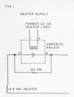
Fig. 1. 6.3 vac HEATER SUPPLY
-------------------
... destroying the heater, a thermistor with the opposite coefficient is placed in series. Then, as the resistor heats from internal dissipation, its resistance falls, keeping a more or less constant current through the heater. This is a well-tried technique used in broadcast equipment and other places where the cost of tube replacement is very high. The only reason not to include it on every tube design (indeed in every light bulb) is cost.
Note that the use of the thermistor I propose above is not the same as that proposed by the Genalex brief; they in corporate a thermistor in place of a relay in the high-voltage line. My thermistor would have a resistance of about 2 ohms cold, and about .2 ohms or less when passing about 4 amps (after reaching a steady state). I do not have a good commercial number for this part, as I have not used thermistors extensively.
Another solution to this problem is to apply heater power through a resistor and short the resistor after 30 seconds or so with a delay relay. Fig.1 shows a circuit for such a scheme, along with part numbers.
The delay relay is easily installed and ...
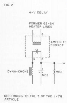
---------- FIG. 2. REFERRING
TO ARTICLE ...
-----------
... should present no problems; it is small enough to go below the chassis if required.
The purpose of the HV delay is to allow the cathodes to reach full emission before drawing current.
If you want to beef up the capacitor, several good ones are available which can be squeezed in below the chassis. Sprague makes a 600 volt, 20 F item; two of these in parallel with C1 give a big improvement in energy storage. Simply connect them from pin 8 of V3 (as shown in Fig. 3 of my article) to ground.
You might also use two larger caps in series. You can buy some reasonably sized 250 uF, 350V ones, which would provide about 12% F of storage. Unless you plan to run the amp at full power with less than 60Hz as the predominant frequency, however, the excess energy storage is just a waste beyond about SF.
As a final note, have you considered RCA’s 7027A? It is a pin-compatible replacement for the 6550, with some features to recommend.
You must be sure that pin 6 wasn't used for anything on the KT88 (it's not connected on the KT88, but is on the 7027A). Aside from that, the tube is a satisfactory replacement in the circuits we are considering, judging from the specifications. I haven't tried them yet, but I hope to obtain some soon. They are not quite as husky as the KT88's; but then, what is?
DON'T MODIFY OLD AMPS!
MY RECENT INTEREST in TAA has been to see if I had missed anything of importance in power amplifier design from having been away from it for a good many years. I have concluded that what I have missed is the "losing of the art." I was horrified to read Eisenson. His suggested modifications to older amplifiers would degrade their performance more often than improve it.
I was also horrified to see the AR (Dell) "metamorphosis'' of the Dyna Stereo 70 in Issue 4, 1977, p.4. Without a detailed analysis, it is enough to say that using seven tubes to do the job that Dyna did with two is a beautiful illustration of the smart-ass school of engineering. The basic circuitry of the Dyna amplifiers (ST70, Mark III, etc.) is impossible to improve on by any significant amount, and any improvement, except by way of parts exchanges and power supply modifications, will not come from circuit changes but from the use of a better quality output transformer, which would make possible elimination of the frequency compensating elements that are ancillary to the basic circuit.
I was interested to see the circuit for the much revered Marantz Model 9 in Issue 1, 1977, p.44. This design lost the ''elegance of simplicity' that Marantz had in what I think was his first preamplifier, the 20-40 unit brought out about 1956 (see Audio, Aug. 1956).
I have settled on the basic configuration but have not yet worked out in detail the design for a tube amplifier I want to build-mainly because I have not found a source for output transformers. Partridge and Gardner's either of whom could easily produce state-of the-art transformers, are now only doing quantity production for OEM's. Do you have anyone with a stock line of very high quality transformers? I recently decided I wanted a headphone amplifier for temporary use, as I had given up the Kenwood 700 series to a daughter. I was going to build one from English modules, but just as I was about to proceed on this I stumbled across an old H.H. Scott model 200 (6GW8's). 1 have been progressively modifying it-mostly by cutting out components, after changing to triode circuitry and it sounds pretty good. What is more, even with output of about half its original 12 watts per channel, it does a fair job of driving two old high efficiency speakers: a Jensen G610 and a Simplex theatre speaker. If the present slight trend back to more efficient speaker systems continues, the tube may rise again.
JOHN W. McCONNELL, Carmichael, CA 95608.
PASS: IS IT CLASS A?
I MUST DIFFER with Nelson Pass in calling his high quality, conservatively rated power amp (TAA 4/ 78, p.49) a 40W Class A amplifier. It is Class A for any load up to 3.2A; at that point it becomes a Class AB unit. This occurs above about 40W with a resistance load; but with a load presenting considerable capacitance or inductance to the amplifier the Class A wattage rating should be considerably reduced or not used at all.
The amp's excellent performance results not from magical "Class A" operation, but rather from the use of high quiescent current and multiple output devices. Looking into the amp's output the load sees transistors operating from about 1-2A, a much smaller range than the typical 50 mA to about 4A in conventional AB amps. The result is simply far more linear output characteristics.
I wonder whether the bias current could be reduced considerably without much performance loss? The benefits might be worth it. For instance, the power supply and heatsinks could be considerably smaller; or the peak-output could be raised while maintaining the same dissipation.
MARK C. SHULTS; Madison, WI 53711
MR. PASS REPLIES:
I AM SORRY to disabuse you of your notion, however the amplifier operates in Class A mode up to 40 watts into 8 ohms regardless of the reactivity of the load, be it capacitive, inductive, resistive, or any combination of these. At currents beyond the Class A rating, the amplifier operates in Class AB, which is standard operation for any push-pull Class A circuit in existing literature.
If you test, you will also find that reduced bias dramatically increases distortion.
MONEY SAVERS
I am writing this in reply to your comment to Mr. Jakowczyk in Letters TAA, 2/ 78. Yes, positive regulators are cheaper than negative ones-ten cents cheaper at the retail level.
But now, in order to use the chassis as the heatsink, you need two sets of mica insulators, etc. If you used a positive and a negative regulator, the cases of each would be at ground potential and would not require insulation. Also, two separate windings would not be required, allowing a much wider choice of transformers. (By the way, Meshna # TR-33416VCT x 2 @ 1A for $1.75 is an ideal one for doing it your way.) Further if you want to talk cheaper, how about skipping the $30 kit from Old Colony and using the existing PAT-S regulator board? Remove the voltage dropping resistors, substitute the regulators (pos. & neg. regulators, using the chassis as a heatsink), add a couple of tantalum caps for stability, and you have just done for about $5 (including Meshna's transformer and the more expensive negative regulator), that which Old Colony's kit does for $30, including the 'cheaper' regulator.
Some time ago in the Letters section, a method was described to measure inductance using lissajous figures on a scope. Here is an easier way: Resistance in an inductor varies by frequency. By putting an inductor and a resistor (non-inductive metal or carbon film) in series across an oscillator and varying the frequency until the voltage drop across both is the same, the exact inductance can be determined. Similarly, by pre-determining the inductance desired and selecting a frequency and resistance accordingly then winding an inductor until the voltage drops equally across the resistor and inductor, a high-accuracy inductor may be wound.
Accuracy is limited only by the resistor's tolerance and the accuracy of your oscillator.
Meter accuracy is not critical because the measurement is relative, not absolute.
Because I wind many coils, I use a simple jig with a DPDT switch to go back and forth between the resistor and inductor. Polarity of the meter should be maintained relative to the oscillator.
Can you identify a retail source for those nifty little stakes you use on some of your circuit boards? (H.H. Smith, Co. is the maker but we know of no retailer.-Ed.)
K. S. SCRIBA; APO San Francisco, 96270
We are always aware that builders can buy surplus cheaper for many items than buying kits from Old Colony, and we hope those who can do so will. OCSL does not sell "'surplus"' items or seconds. OCSL is a convenience for those who can't find the parts they need, and OCSL's parts buyer cannot order and stock parts for the love of it. He must be paid. -Ed.
LIPSHITZ TO CURL
I find I am in almost total agreement with John Curl's second and third paragraphs (TAA 1/79, p.49), and I hope my push for accurate RIAA equalization is not misinterpreted-I simply believe it to be one of the main causes of audible differences between components, differences which the underground audio press usually misunderstand and which are relatively easily avoidable by good engineering. Our comments in response to the Jung/ White letters (this issue, p.52) should further explain my reasoning.
If phono preamps do indeed run into slew rate limiting when fed with the ultrasonic tracing and pinch distortion components which a moving coil cartridge’s wideband electrical system lets through, I wish Mr. Curl would make his measurements available to us. Certainly the phono preamp should be designed to digest such ultrasonic garbage (not present in the original mike signal) without sending audible intermodulation, and preferably also without sending it on to subsequent stages. Not having tested Mr. Curl's two preamps
R Letters myself, I cannot even try to explain the audible differences he believes exist between them. I strongly encourage him to conduct a double blind comparison test, as outlined in our letter on pp.52-3, and report back on the outcome.
STANLEY P. LIPSHITZ University of Waterloo Waterloo, Ontario, Canada
VORHIS + JUNG = PLEASURE
I AM ONE of the many pleased readers who have modified the PAS following David Vorhis' article in Issue 2, 1976, p.21, but am proceeding to go the full route up to the SP3Al. Vorhis' article and TAA in general make me glad I have stuck with my old PAS through the solid state revolution.
Has anyone used the tone controls in Walt Jung's article in Issue 1, 1975, p.22, in a PAS/ SP-3A-1 conversion? I would like to hear any comments.
RICHARD M. JOHN Fincastle, VA 24090
HAILS HALL
I SUGGEST Orchestra Hall in Minneapolis as a "current example of a building where scientific principles and proper priorities combined to give us a good building” (Issue 2, 1976, p.42). (Correspondent Smith includes excerpts from Time, 4 Nov. 1974, and one of the country's best critics, Harold C. Schonberg of The New York Times, praising Orchestra Hall. -Ed.| It is ironic that those scientific principles suggest that the great concert halls built long ago, following tradition as to shape, building materials, and interior finishing, are about as good as what we can build now. At least we have the satisfaction of knowing why a hall sounds as it does, and further proof of the "soundness'' of musical tradition.
TOM SMITH Minneapolis, MN 55408
FM: LIMITERS, EQUALIZERS
AFTER READING ROY TRUMBULL'S guest editorial heralding “The Decline and Fall of FM" (TAA 4/ 77, p. 3), I have several observations.
The first pertains to the use of a limiter (as opposed to other types of audio processing devices) in FM broadcasting. The proper function of this device is to prevent over deviation (overmodulation) of the FM carrier. Such protection is necessary for three reasons: receiver distortion, spectrum conservation, and the FCC.
In currently-designed receiving equipment the trend is toward the use of highly selective lumped crystal or mechanical filter networks in the IF strip to improve adjacent-channel rejection in crowded signal areas. To avoid the loss of the outer sidebands the bandwidth of the transmitted signal should be carefully controlled. In addition, if the linear frequency -to-voltage conversion range of the receiver demodulator is exceeded, its output may saturate or become random (as in the case of an unlocked PLL), resulting in sharp increases in harmonic and IM distortion and crosstalk levels.
From a spectral point of view, 100 channels, each 200kHz wide, are available for broad casting. Although the bandwidth of an FM signal is theoretically infinite, in practice it is usually determined by the number of significant sidebands (generally 1 percent of carrier amplitude or greater), which in turn depends upon the amount of deviation and the modulation frequency. Thus it follows that to prevent interference to adjacent-channel stations and thereby make the best use of the available space, these two latter quantities should be controlled.
As a part of its Automated Transmitter System (ATS) docket, the FCC has clarified its interpretation of the rules concerning overmodulation. As a result, licensees can expect to see tighter enforcement of the rules.
All these factors indicate the use of a limiter in FM broadcasting is appropriate, and indeed necessary. Unfortunately, much of the limiting equipment available to the broadcaster has been designed to standards well below what most of us would consider to be 'high fidelity.'' This situation is changing, however, and current equipment is available with vastly improved performance.
To the purist there remains the problem of loss of high frequency response. FM limiters, to be effective, must utilize a limiting characteristic which follows the inverse of the 75 microsecond pre-emphasis curve. The problem lies in the fact that the compression is not reversible at the receiver.
As for the use of other audio processing devices in the chain, one may certainly say discretion is the order of the day. For example, certain formats such as ''beautiful music'' and rock do not seem to require a transmission channel with wide dynamic range, while others (notably classic) do. The processing needs to be geared to the type of programming, which means several different setups may be needed in varied format situations.
Most stations which use processing find it desirable because their signal becomes just a bit brighter, cleaner, and louder than the com petition. Such effects are not lost on the listening public, and since advertising rates are determined by audience size they become important in a competitive market. The signal-to-noise improvement, incidentally, is just as helpful in the primary service area as it is in the fringes.
In order to see how this might affect a local listener, let us examine what happens when a stereo FM station is operated with no limiting or processing of any kind.
In order to avoid overmodulation on high frequency transients (particularly common rock, disco, and jazz material), the modulation level must be set so mid frequency material (around 1kHz) peaks at about 15 percent modulation (not including pilot), due to the pre-emphasis characteristic. (Even so, relatively minor-sounding ticks and pops in recorded material will occasionally pin the monitor at 133 percent!) The average modulation level will be somewhat less--perhaps 10 percent. Now, if the listener is using a stereo receiver with 60dB of ultimate quieting (and many are worse), his average received SNR will be only about 40dB. Thus techniques which in crease the average modulation level can benefit all listeners.
The use of graphic equalization in broad casting is subject to the same arguments, both pro and con, as its applications in professional sound reinforcement and audiophile installations, where it is widely accepted. It solves some problems but can create others, as the editorial mentioned.
However, the broadcast engineer concerned about phasing in his system would do well to pay particular attention to his studio-to transmitter link, which is frequently a pair of telco lines.
Mr. Trumbull might be surprised to know that unfortunately not all FM exciters have 15kHz low pass filters in each channel. This endangers not only the pilot, which is generally protected with at least a notcher, but also the L-R subchannel region. Any high frequency distortion components reaching the exciter will be matrixed into both sub channels so both mono and stereo reception are affected. On the other hand, if the exciter is properly low-passed (a process which can introduce problems of its own-notably overshoot) it does not matter what harmonic components are present above 15kHz. If they are not transmitted, they are not received.
And that is that.
As for the low end response, most currently available transmitting equipment is capable of adequate performance. Using balanced transconductance modulation techniques in the stereo generator, an exciter could be constructed with response down to DC; however, such a device's utility would be questionable. Imagine having the carrier frequency jump 7S5kHz (or more, unless a limiter operating down to DC was available) every time an operator bumped a stylus or microphone or started up a cart (not to mention turntable rumble)! Broadcasting is an art, a science-and a business. Although we would all do well to remember that latter point, it does not imply that good engineering standards must be abandoned. Rather, it should be a challenge to use our creativity to ''shape the medium to the message." Instead of asking the government to set arbitrary standards for us, we should take the initiative and let the listener make the choice. Only in this way will we build an industry which is responsive to new techniques and public needs and which is incidentally cognizant of the worth of a good broadcast engineer. We may, in fact, be embarking upon the era of the recovery and resurgence of FM!
EDGAR C. REIHL Broadcast Consultant Evanston, IL 60201
OSCILLATOR/ANALYZER COMMENTS
WALTER MORREY PROVIDES a good hard look at the Heath 1G-1272 oscillator, and his digging and comments benefit us all. I believe, however, he overstates the case in picking on the BNC jacks.
As many have noted, phono plugs are designed for very limited connection and disconnection, one time preferred. They do have better shielding than double-banana plugs (typically without a shield), but reliability with usage is quite poor. BNC jacks and plugs are much higher in price, but not in total dollars for a small number of jacks. Keep in mind also that much test equipment is supplied with BNC jacks, and that BNC-to-phono jack adapters cost the same or more than BNC cables, if you make your own. Finally, I expect quite a few of us have found $40 for BNC cables but not $2000 or so for a Sound Technology unit.
Gloeckler's review of the Heath IM-5258 THD analyzer (Issue # 2, 1978, p. 45) is both succinct and informative. I agree emphatically with him on the poor human engineering in some areas. If nothing else, as Gloeckler points out, Heath should change the dB scale so its zero reference is full scale to match the harmonic distortion level set. Still, it works quite well for the money. With an external level monitor and control for setting 0.316 volts for the set level reference, the unit is fairly fast even for repeated tests or for getting HD vs. level data.
Fig. D in the kit report box (p. 48) shows the essential characteristics of THD measurements of a tape recorder output, as well as the true distortion values obtained with a spectrum analyze. Although the HD meter will not provide reliable figures below meter zero or thereabouts, the information obtained at the highest levels can be used to determine the 3rd harmonic distortion function. Note that in the figure the 3rd harmonic plot is very close to a straight line; so it is with most recorders and tape formulations.
Also note that this line is the asymptote for the THD curve, and it should be, for the 3rd harmonic is predominant generally in the tape recording process, and the signal is well above noise influences.
We can get fairly reliable '"date'' on low level 3rd harmonic distortion by this process:
(1) take THD data vs. record level starting from at least 3 per cent THD; (2) repeat the measurements for each dB reduction in record level; (3) if you can do so easily, record the distortion level in relative dB- for each dB reduction in record level, the distortion level should drop about 2dB (+ 0.5dB); (4) continue to take data until the reduction in distortion slows up, approaching the noise limitation with this approach; (95) plot the data in linear dB, distortion level vs.
record level; (6) match the upper, straight line portion of the points, and draw a straight line to perhaps -10 VU or so. The result is really fairly accurate and will allow com paring the performance with various tapes, bias settings, etc.
Those interested in additional discussion of these elements may refer to AES Preprint No. 1063, ''Spectrum Analysis of Tape Recorder Distortion," presented at the November, 1975, convention.
HOWARD A. ROBERSON
Pittsfield, MA 01201
FM DIVERSITY RECEPTION
IS IT POSSIBLE to devise a diversity system for FM reception? I base my belief on the idea that some FM stations have both vertical and horizontal transmitting antenna systems.
It should be possible to use vertically and horizontally polarized antennas at a receiver to achieve reception from long distances.
A possible configuration would include two antennas, two automatic gain-controllable RF preamplifiers, one FM receiver, and one hybrid matching transformer. The operation of the diversity systems depends on the vertical and horizontal reception paths reacting differently. The nice feature is that the antennae do not have to be a great distance apart as in space diversity.
My idea is that the signal paths create varying signals which are amplified by an AGC-able RF preamplifier for each path. The hybrid transformer combines the preamp's output and feeds it to an FM receiver. The AGC developed in the FM tuner is applied to the preamps and reduces the signal from the low signal path. The overall signal level should be 3dB better than a single antenna.
There should be noise reduction via the action of the hybrid transformer.
RICHARD MCCLEARY Jacksonville, FL 32210
PAT-5: LISTENING TESTS--AN ALTERNATIVE VIEW IN HIS RESPONSE (TAA 3/ 78, pp. 49-53) to a letter from Stanley P. Lipshitz, Walt Jung asked us to try the WJ] -1 phono stage design in comparison with the PAT-S and report on our experiences. In fact, he was kind enough to furnish us with closely matched resistors for the circuit of the modified phono preamplifier, and TAA's editor was equally kind in supplying the necessary JW-33 boards for the test.
We have now built these boards and con ducted the comparison test suggested. This report on the results will also furnish Dave White with replies to his questions (TAA 4/ 78, p.55).
To begin, let us explain how we conducted the test. We powered the JW-33 boards from a regulated -15V supply, and drove them from our Shure V-15 Type IV cartridge in parallel with the PAT-5 phono stages. Although this meant the cartridge was not optimally loaded, we did it to ensure that both phono preamplifiers were always driven with the identical signal, thus totally eliminating the effects their different input impedances could have had upon the cartridge's output as a function of frequency.
Having thus ensured no frequency response differences were being introduced by differences in cartridge loading, in our next step we eliminated the RIAA equalization differences between the two phono stages- specifically, the deviations of almost a decibel between the inaccurate equalization of the PAT-5 and the accurate J W-33. We fed the PAT-5 tape output into a modified Dynaco SE-10 octave equalizer. The equalizer output then went to the A/ B remote relay controlled switch box, where we could select either it or the JW-33 output and send it on to the higher level stages of our preamplifier (Apt/ Holman, with all filters defeated) and thence on to the power amplifier (modified QUAD 405) and loudspeakers (QUAD electrostatics). We had previously auditioned the equalizer on a straight wire bypass test and could not distinguish it from the bypass.
We fed the two preamps from a signal generator via an inverse RIAA network and adjusted the equalizer-an excruciatingly painful task-until the PAT-5 frequency response and gain matched that of the JW-33 boards to within 0.05dB from 30Hz to 15kHz.
Finally, we used another relay in the switch box to invert the polarity of the loudspeaker signals when the JW-33 was in circuit, thus compensating for its internal polarity in version.
As readers will have gathered, we thus arranged the test set-up so as to take into account both factors believed by S.P.L. in his letter (TAA 3/ 78, pp. 48-49) to be the primary causes of audible differences between ''good"' phono preamplifiers, namely frequency response differences caused by cartridge interaction and RIAA equalization errors, and polarity errors. If he was correct in his belief, the two phono preamps should now have sounded identical. The three undersigned took part in the listening test, which included a variety of records of all descriptions which we have come to rely on for showing up various system deficiencies.
These included discs which by measurement we have found to have exceedingly high slew rate (i.e., acceleration) modulations. We should also mention that the switch box uses hermetically sealed bipolar relays and it incorporates a randomizer circuit which enables the test to be conducted double blind, so that at each trial no one knows which preamps is "A'' and which is "B”.
Well, we started the test and lo and behold, we could distinguish between the two preamps. The differences were subtle, but we could reliably characterize the audible differences. So we rechecked the equalization accuracy and found it to be in error by 0.1dB over a single octave around 8kHz. We corrected this by further laborious knob twiddling--try it if you don't believe how difficult it is to achieve tenths of a decibel equalization accuracy! Further listening showed that we could still distinguish reliably between the preamps, but now their characteristic sounds had interchanged: i.e., the characteristics which we had previously heard from preamp “X” we now heard from preamp "Y''! At this point the differences
were extremely subtle, and the two frequency responses agreed to within 0.05dB from 30Hz to 15kHz, the lowest and highest bands on the equalizer.
If nothing else, the test up to this point had shown that extremely minute frequency response differences were detectable on an A/ B test-differences so small as to be in significant when no A/ B test is possible. In a flash of inspiration someone suggested we check the equalization above 1S5kHz, and indeed we found the two preamps still differed by 0.2dB at 20kHz due to the rolloff effect of a connecting cable's capacitance following a potentiometer on the output from the SE-10 equalizer. We eliminated this pot and used the equalizer's gain controls for gain equalization. The frequency responses were now within 0.05dB from 30Hz to 20kHz, and only 0.2dB different at 25kHz. Again we listened, and listened and listened-no difference! Try as we might, we could not now distinguish between the two preamps.
However, neglect to correct for their relative polarity inversion, or introduce a small frequency response deviation, and we could again repeatably distinguish between them.
So where does this leave us? We have demonstrated an ability to detect extremely small and subtle differences due to linear deviations between phono preamps--i.e., deviations in gain, frequency responses, and polarity-and have shown that (at least for this test set-up and the two preamps in question) when these linear differences are removed they become indistinguishable {from each other. This means whatever nonlinearities they exhibit are so small as to be inaudible when the linear deviations are removed, and certainly to be completely overwhelmed by the linear deviations when they are not removed.
Consequently, we can conclude the differences in the nonlinearities (which cause harmonic, intermodulation, TIM, and other similar distortions) present in ''good'' phono preamps are below audibility when the preamps are fed from a moving magnet cartridge (which electrically prevents ultrasonic tracing distortions above 30kHz from reaching the phono preamp). We thus believe we have demonstrated that the audible differences between the PAT-S and WIJ -1 phono sections (which most certainly are present-we have never claimed otherwise) are due entirely to their linear differences, specifically their frequency response and polarity.
Now let us be perfectly clear on one point.
On all objective criteria the WJ-1 is better than the PAT-S. Its RIAA equalization is exact and its nonlinear distortions of all kinds are much lower. Certainly it is a better design-on that there is no argument. But the reason it sounds different is its linear differences, and these are exactly equalizable as shown by our test. An A/ B comparison, either long or short term, will always show up such differences, even as little as 0.1dB, as we have seen. However, since no microphones or source material are achievable with such phenomenal accuracies, in the last resort these small differences are immaterial, although detectable.
Let us summarize our conclusion. Not all
'*good'' phono preamplifiers sound alike. The audible differences between them can be exactly accounted for by their linear differences (i.e., gain, frequency responses,
polarity), extremely small deviations in these parameters being audible if one has suitable source material which is not itself phase-garbled through multi-mike recording, if one uses loudspeakers of sufficient ac curacy not to obscure the differences (a tough criterion to meet!), and if one knows through experience what to listen for. These linear differences have little to do with circuit topology or configuration, but much to do with good engineering and RIAA equalization accuracy, something which a high price does not necessarily buy. Such equalization errors should ideally not be present to begin with, but can be eliminated by equalizing (i.e., "tone controls'), and in the final analysis are not of great importance relative to the program material available. On an A/ B comparison, however, they explain the differences heard between phono preamps.
We would be most interested in hearing from readers concerning our conclusions; but please be aware that, unless you go to the trouble of controlling all the variables in any test you conduct, your conclusions will be open to question. This applies to most of what you read in the "underground" audio press.
So if you want a reply, be sure to control your test fully and explain how it was conducted.
(Sorry about our conditions, but they are made in self-defense!).
STANLEY P. LIPSHITZ JOHN VANDERKOOY PAUL YOUNG University of Waterloo; Waterloo, Ontario, Canada Note: A reply from Walt Jung and Dave White will appear in the 3/79 issue. - Ed.
PANDORA HAD PROBLEMS, TOO
THE EDITOR PASSED ON some enquiries about the touch-switch selector module I showed in my custom control unit article (TAA 1/ 78,p.4), and I promised to do a short piece on its design, with a diagram or two. As the unit has been working for three years, I did not expect much difficulty in supplying guidance for those wishing to make their own versions. Alas, the little green men are too well established in this module for me to unleash the schematic on unsuspecting readers. Let me explain.
The circuit uses two IC's (SAS 560 and S70, originally designed for television touch tuning) to switch reed relays controlling the audio inputs directly to a mixer and at the same time light LED's to indicate the function. This has three advantages: the unused inputs are completely isolated by the reed contacts; the IC design allows a
'preference' input; and the connection is free from stray voltages.
I am now in a position, as the politicians say, to reveal the disadvantages as well:
1. The IC's are loaded to their maximum safe current and into an inductive load.
Therefore you cannot allow the rail voltage to surge.
2. Reed relays are usually make contacts, so you cannot ground the unused inputs to prevent breakthrough.
3. An interaction between the IC's, the reed coils, and smoothing components on the rail gives a ''buzz'' oscillation on the switched input under some grounding conditions.
4. Due to disadvantages 1 and 3, you can Letters switch only one input at a time; thus you lose a mixing facility.
Now I know disadvantage 1 can be solved by relay driver transistors and a zener or two; the interaction would also probably respond to a separate supply, and the breakthrough has not yet proven to be a serious problem. But unfortunately I have not the R&D time available to cure these and the other snags that will arise when I redesign- and enlarge-the board!
ALAN WATLING Colchester, Essex, England
TANTALUM CAPACITORS: YES OR NO? NO! WHAT I SAID (see Letters, Issue # 2, 1978, p.50) is what I meant: tantalums are not suitable for state-of-the-art designs.
The best designs will use DC coupling; but if you have to use capacitors, don't use Al aluminum or Tantalum types. Although I realize capacitors used in the signal path are often a practical solution to many problems (cost being one-add a capacitor and forget about DC offsets due to temperature drift, for example), what can be done to reduce the effects of non-ideal capacitors on the circuit and hence on sound reproduction?

FIG. 1
Take a look first at Fig. I, the 4. uF/ 50V tantalum capacitor line. The curve beginning at about 30kHz represents deviation from what a capacitor is. Inductance and equivalent series resistance prevent the impedance from continuing its descent: it actually starts to rise again. These curves, taken (by permission) from Siemens Capacitors Product Guide, are good, for tantalum capacitors; not all Ta caps are this good.
Now look at the 4. uF curve of Fig. 2. This shows the same values except in this case the voltage rating is 10V. As you can see, its performance is appreciably worse, becoming non-linear well within the audio range.
So the first thing we can do is use the high voltage ratings, not the minimum (and least expensive) that will serve.
Another way to improve a large value...
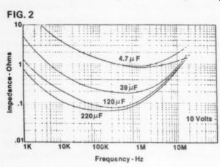
FIG. 2 impedance
...capacitor's circuit performance is to parallel | it with a smaller value, high quality type which will continue the impedance curve downward and offset the inductive component of large Ta capacitors. Suitable shunting capacitors are mylar, ceramic, polycarbonate, or polystyrene types.
Modifications to existing equipment such as bypassing power supply filter capacitors with high voltage tantalums, using polycarbonate or, better still, polystyrene caps in RIAA feedback networks, and bypassing large electrolytics make for dramatic sonic improvements.
Replacing Al or Ta types where possible helps immensely; but I like the saying, ''the best capacitor is no capacitor at all." State of-the-art audio design will be pushed a bit further by designs which can use a minimum number of caps.
D. Marsh
Berkeley CA 94550 y
PASS ON CAPACITORS
I WAS INTERESTED in Dick Marsh's letter on tantalum capacitors used as AC coupling in a signal path (Issue # 2, 1978, p.50) because I have some information of my own on the subject.
While the values of D and C will alter with frequency between 1 and 10kHz, such capacitors are generally seen as coupling with rolloffs at frequencies less than 10Hz.
Because the effect of such variations varies inversely with frequency, we find 50 percent variations in C at 10kHz for the amp concerned will result in a factor of .0001 of amplitude variation.
I have not found much evidence that D and C are problems in audio AC coupling;
however, tantalum capacitors will exhibit harmonic distortion as a function of signal amplitude and the RC time constant of the capacitor and resistor in the network.
Generally, I find that .001 percent 2nd harmonic distortion will appear at freq.(Hz) RC at an amplitude of 1 volt rms. At lower frequencies the distortion rises, and at higher frequencies the distortion vanishes. At the cutoff frequency we about .03 percent; thus tantalum capacitors should not be used for AC filtering in crossovers and such and are only suitable when their rolloffs are significantly low. For example, in the project amplifier the low frequency rolloff occurs at 1.5Hz, which will yield distortion on the order of 0.001 percent at about 10Hz or so at half power. Second harmonic at this amplitude and frequency is acceptable in this case;
however, lower capacitance values would bring higher distortion into the audio region and should be avoided. The paralleling of polycarbonate or similar high quality types unless they are as large in capacity; while they don't hurt, they do not seem to be of measurable value. The distortion is more or less independent of the bias voltage across the capacitor, and the capacitors work well E 2 without DC bias as long as the reverse voltage isn't excessive. Interestingly, cheaper aluminum electrolytics do not exhibit this phenomenon and I would say can be considered equally.
NELSON PASS, President
THRESHOLD CORPORATION
Sacramento, CA 95815
++++++++++++++
Also see:
Audio Aids, 1/1979, by readers Squires, Hill, Caldwell, Thompson, Winn, Hardwick, Moritko, and White
Build A Microphone Preamp (Audio magazine, Feb. 1979)