In addition to color tv receivers, most other consumer electronics and entertainment electronics items are a combination of both electronic and mechanical components. Both radio and audio circuits are combined in compact stereo tape decks, boom-box players, portable players, and telephone-answering machines. Electronic audio circuits are found in turntables and high-power amplifiers ( FIG. 1). Special video circuits are used in VCRs (video-cassette recorders). The automatic CD player, using electronic laser sensing, produces almost noiseless music with a dynamic range and accuracy never heard before.
Although electronic and mechanical movements have been used in consumer electronics products for many years, the beginning of the many new products to come in the years ahead has not even been seen. Electronics and mechanics are a powerful combination for making life easier and more comfortable in this busy world ( FIG. 2). Especially today, the electronic entertainment product is better constructed and more durable. However, when electronics and mechanics are combined together, sooner or later, breakdown occurs.
Required test equipment
To keep the electronic units in tip-top shape, a few basic test instruments are required. The beginning hobbyist often has a VOM (volt-ohm-milli-ammeter), DMM (digital multimeter), and noise generator handy for continuity, voltage, and resistance measurements. The intermediate hobbyist or electronics student might know how to operate the oscilloscope, audio signal generator, and external audio amplifier. The electronics technician should have a frequency counter, advanced digital multimeter, transistor testers, distortion analyzer, dual-trace scope, digital capacitor meter, test gauges, and test discs on the service bench to provide accurate and precise adjustments to audio and video products. A remote-control transmitter tester is a handy gadget to test those infrared- and ultrasonic-type remotes.

FIG. 1 Here the electronics technician is doing transistor tests of the AF
(audio frequency) amplifier transistor with the diode test of the DMM.

FIG. 2 This small Sony cassette player is only one of the many electronic
products that provide easy listening and entertainment.
VOM and DMM
From the beginning, the volt-ohm-milliammeter (VOM) has been the old standby tester of the electronic industry. Every electronic hobbyist or technician should have a portable VOM meter. Fairly accurate voltage, resistance, and current measurements can be made with the VOM pocket meter. Today the digital multimeter (DMM) has practically replaced the VOM ( FIG. 3). In addition to normal voltage and resistance measurements, the DMM can make accurate low-voltage and resistance measurements required for transistors and integrated circuits (IC). Open or shorted tape-head and motor windings are easily located in the tape, disc, and VCR player/recorder. With the additional diode test, you can check for an open or leaky junction of the suspected transistor on the DMM. The low-priced, pocket-type DMM is a handy tester that can solve most service problems related to electronic and mechanical operations.

FIG. 3 Checking a 2.5A (ampere) silicon diode with the diode test of the
digital multimeter. Besides accurate voltage and resistance measurements on
transistors and IC components, the DMM can also test diodes and transistors
in the circuit.
Noise signal injector
You can quickly locate the defective stage with the hand-held noise signal generator at both audio and RF (radio frequency) circuits of the AM/FM table and car radio. The signal can be injected at the oscillator and IF (intermediate frequency) stages clear through to the speaker because the generated harmonics can appear in the megahertz range. Simply inject the noise signal at the base and collector of each transistor until you hear the noise in the speaker. Then take voltage and resistance measurements. You can assume the IC component is defective if you hear a signal at the input and you hear no signal at the output terminal.
The dual-trace oscilloscope
Although the scope has appeared on the service bench for many years in TV servicing, the new dual-trace 45—100 MHz (megahertz) test instrument is ideal for video and audio tests ( FIG. 4). Both audio stereo channels can be checked at the same time, indicating weak, distorted, and intermittent components. The dual-trace scope can be used in AM/FM/MPX alignment procedures. Compact-disc signal tracing, alignment, and offset adjustments are critical tests made with the oscilloscope ( FIG. 5). Locating correct wave forms and adjustments in the VCR circuits requires a high-frequency scope.

FIG. 4 The dual-trace oscilloscope is the ideal test instrument for making
alignment and taking waveforms in the AM/FM/MPX, VCR, and compact-disc player.
Miscellaneous test equipment
The digital multimeter is the ideal instrument in taking critical voltage measurements, and the VTVM (vacuum tube voltmeter) is required in compact-disc and receiver alignment procedures. The audio-frequency oscillator generator is used in signal tracing and distortion tests with the critical audio circuits. A digital capacitor meter can locate the intermittent or open capacitor in audio or video circuits ( FIG. 6), and the frequency counter, distortion analyzer, and laser-power meter can help you perform critical adjustments in audio and compact-disc players. Although many of the miscellaneous test instruments are not required by the beginner or intermediate student, the electronics technician must be able to operate most test equipment in order to service today’s diverse assortment of electronic devices.

FIG. 5 Signal trace each waveform in the CD player to locate the defective
component.
Simple troubleshooting procedures
Before attempting to replace the defective component, consider a few concise trouble shooting procedures. The defective component can be located with a block or schematic diagram, voltage and resistance measurements, and accurate transistor or IC component tests. Try to isolate the defective stage with symptoms and the block diagram ( FIG. 7). After locating the defective stage on the schematic, take critical voltage and resistance measurements, and then perform accurate transistor and IC tests.

FIG. 7 Isolate the defective stage with the block diagram and then locate
the defective component with signal-tracing methods.
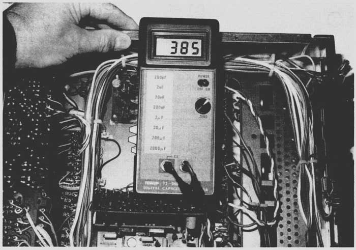
FIG. 6 The digital capacitance meter can quickly locate open or dried coupling
and filter capacitors in the audio circuits of electronic entertainment products.
How to locate the defective component
The open or leaky transistor and IC components are easily located with transistor and critical voltage measurements (FIG. 8). Usually the open transistor indicates a higher than normal voltage at the collector terminal. Remember, the open transistor under test can be shocked into operation when the test probes are applied to the transistor leads. Usually the leaky transistor shows a low-ohm measurement between at least two elements of the transistor. The diode and transistor tests of the DMM will quickly indicate a leaky or open transistor.
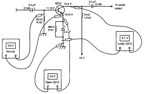
FIG. 8 An open or leaky transistor can be located using critical voltage
measurements on the collector and emitter terminals. The normal NPN transistor
should have a 0.6 V (volt) forward-bias voltage.
The defective IC component can be located with critical voltage measurements, signal-in, and signal-out test procedures. Usually, if the IC component has very low voltage on the supply terminal when an RF or AF (audio frequency) signal is injected at the input terminal, and there is no signal at the output, you can assume the IC or components surrounding the IC are defective. The same test applies when the signal is found at the input but none is found at the output terminal of the IC component. Critical voltage, resistance, and capacitor checks of components tied to the IC will locate the defective component.
The intermittent transistor or IC component can be located with critical, monitored- voltage tests, signal-in and out, and audio signal-tracing methods. Often, the intermittent transistor or IC component can be shocked into normal operation when test leads are applied to the component or nearby. Try to make the intermittent component fail by cooling or heating it. Use a few coats of spray coolant and heat from a hair dryer. RF and audio signal-tracing procedures can then locate the defective component.
Using the digital multimeter (DMM)
The digital multimeter is one of the most versatile test instruments designed in the past few years. Very low and critical voltage measurements made with the DMM can locate a defective transistor or IC or a leaky component. Usually, a quick low-voltage measurement between emitter and base terminals indicates if the transistor is defective ( FIG. 9). NPN transistor bias voltage is 0.6 V for silicon transistors and 0.3 V for germanium transistors. The junction of the transistor can be further tested with the diode-transistor test.

FIG. 9 The junction of a transistor can be tested in or out of the circuit
with the DMM diode tests. The base terminal (B) of the transistor is always
common to the collector (C) and emitter (E) terminals.
Improper or very low voltages on the IC component can indicate a leaky integrated circuit. Very low voltages on certain IC terminals might indicate a defective IC. If the supply voltage is very low on the supply voltage terminal, you can assume the IC is leaky. To perform the low-voltage measurement, remove one lead of the suspected bypass capacitor tied to the IC terminal. Now take another capacitor test. The signal-in and out test of the IC while it’s running red hot will locate the leaky or shorted IC component quickly (FIG. 10).

FIG. 10 Critical voltages on the IC terminals can indicate a leaky or open
component. Low voltage at the supply terminal (Vcc) often indicates a leaky
IC.
Voltage and resistance measurements with the digital multimeter
The digital multimeter is the ideal instrument to take critical voltage and resistance measurements for in-circuit tests. Besides reading very low voltages on a transistor, the bias voltage test will indicate if the transistor is defective. When no bias voltage (0.6 V) measurement is found between base and collector terminal of a silicon NPN transistor, you can assume the transistor is defective. If the collector voltage is higher than normal, with no emitter voltage, the transistor is open. Very low collector voltage with higher than normal base and emitter voltage might indicate a leaky transistor. The emitter voltage might be quite high if the emitter resistor is open.
Critical voltage measurements on the IC component might indicate a leaky or open IC ( FIG. 11). First, measure the supply voltage terminal of the IC component. Very low terminal voltage might indicate a leaky IC. Higher voltages on other elements of the suspected IC might indicate open internal components. If the supply voltage terminal is very low, remove the IC terminal with solder wick and take another voltage measurement at the pin. The IC component might be leaky if the supply voltage rises above normal. Now, take a resistance measurement of the supply IC pinto ground. A measurement of less than 1 k-Ohm indicates a leaky IC component ( FIG. 12).
Accurate resistance measurements of transistor and IC bias resistors might turn up an open or an increase of resistance. Take accurate resistance measurements between each IC pin and common ground and compare them with the schematic. If the resistance is fairly low, remove the suspected pin from the circuit and take another measurement. If the resistance measurement is now increased, suspect a leaky IC. Sometimes a leaky capacitor can be located with accurate resistance tests between IC pins and ground.

FIG. 11 When lower than normal voltages are found on the IC, suspect a defective
power supply or leaky IC. Remove the voltage supply pin from the circuit and
see if the voltage increases, indicating a leaky IC component.

FIG. 12 Remove the suspected leaky pin from the PC (printed circuit) board
wiring. Suspect a leaky IC if the resistance to chassis is less than 1 k-ohm.
How to test transistors in the circuit
Transistors can be checked in the circuit with accurate voltage measurements, a transistor tester, and a diode-transistor test with the DMM. Accurate forward-bias voltage measurement between emitter and base terminals might indicate if the transistor is normal. The normal silicon NPN type will have a 0.6 V bias, and the PNP germanium transistor will have a 0.3 V bias measurement. Several transistor packages are shown in FIG. 13.

FIG. 13 The normal NPN type transistor has a 0.6 V forward bias between emitter
and base, but the PNP germanium transistor has a 0.3 V bias.
There are many good transistor testers on the market that make in-circuit tests. The DMM diode-transistor test is accurate. Within minutes, you can test all the transistors of the audio channels. Remember, the base terminal is the common test point between NPN and PNP transistors. Place the positive test probe to the base terminal of the transistor and the negative probe to the collector and then the emitter terminal. A normal comparable resistance measurement will be found between base and collector and between base and emitter. If the measurement is very low, suspect a leaky transistor, and suspect a leaky transistor with a low measurement in both directions. You should have only one reading in the forward direction with a normal transistor. A measurement in both directions indicates a leaky one. Reverse the test leads for the PNP types. Place the negative (black) probe at the base terminal and take the same test. Of course, an open transistor will have no measurement in any direction.
Additional test equipment
In addition to the DMM, oscilloscope, transistor tester, tools, the audio signal tracer and sine-square wave generator can help locate the defective component. The sine-square wave generator with the scope as indicator will quickly locate a defective component producing weak or distorted audio. The audio signal generator can quickly locate a defective stage. Why not build your own audio tests instruments if you don’t have them on your service bench?
Audio signal tracer
The audio signal tracer can be constructed on a PC (printed-circuit) board or predrilled board. All small components can be mounted on the universal board with the transformer and speaker inside the cabinet. In fact, a small 5 or 6 inch speaker baffle can house all the components.
The audio amp circuit ( FIG. 14) consists of a high-impedance FET (field-effect transistor) (Q1) and audio output stage (Id). C1 should have a 450 V working voltage, to prevent breakdown in higher voltage amplifiers. Excessive picked up audio is controlled by volume control (R5). The signal tracer can be operated from a 12V dc source or ac regulated power supply. Capacitors C10 and C11 are wired in parallel to eliminate any ac hum in the amplifier circuits. All parts are available at most electronic stores.
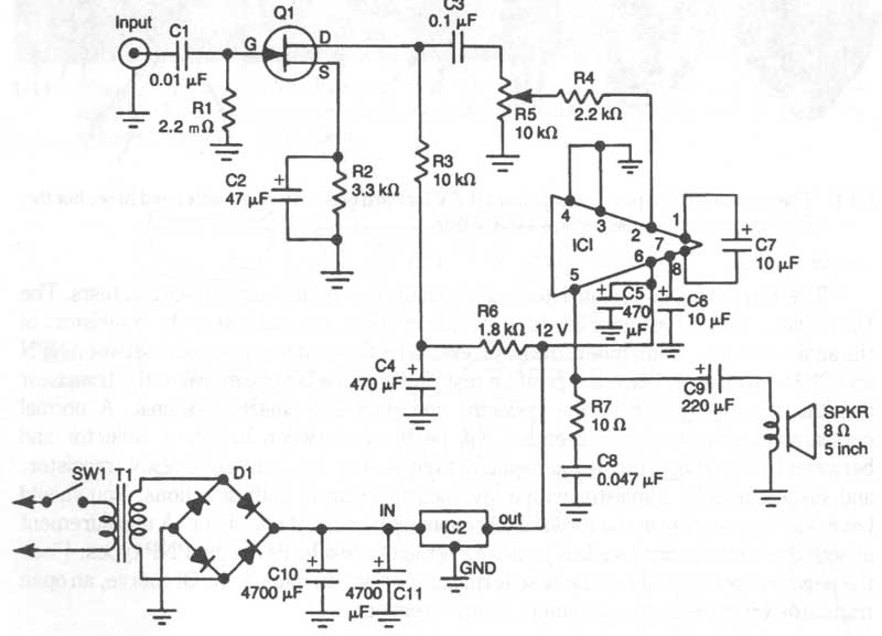
FIG. 14 The schematic diagram of the audio signal tracer with ac power operation.
Parts list for the audio signal tracer:
Miscellaneous: Speaker, ac cord, 4½ x 6 inch predrilled board, nuts, bolts, etc.
Sine-square wave generator
A 1CL8038 function-generator IC ( FIG. 15) produces a very stable sine and square wave for signal tracing. Although 1C8038 delivers sine, square, and triangle waveforms, only the sine- and square-wave terminals are used. These two waveforms are switched with SW2 to a common transistor (Q1). The output signal is taken from the emitter circuit of Q1 with R10. The small generator is powered by an ac regulated power supply.
After the unit is constructed and ready for testing, adjust R6, R8, and R9. Connect the scope input terminals to the function generator. Flip SW2 to the sine-wave position. Adjust R8 and R9 alternately for a good sine wave ( FIG. 16). Try to make the sine wave round at each end. Slightly touch up the output with R6.
Move 5W2 to the square-wave signal. Re-adjust R6 for a good square-wave signal ( Fig. 147). Slightly touch up RB and R9, making sure the sine wave is not distorted. Once RB and R9 are properly adjusted, the waveforms won’t change when the frequency is varied.
Parts list for the sine-square wave generator

FIG. 15 The schematic diagram of a sine-square wave generator operating from
an ac power line.

FIG. 16 Adjust R8 and R9 with a normal sine wave at the generator output,
indicating with a connected scope.
FIG. 17 Switch SW2 to the square-wave output and adjust R6 for normal square wave on scope. If needed, touch up R8, R9, and R6 for both normal waveforms.
SPDT (single-pole, double-throw) toggle switch
PF chassis, 14-pin IC socket, bolts, nuts, etc.
Too hot to touch

FIG. 18 A transistor or IC component that is too hot to touch often indicates
a leaky or shorted condition. Check for burned wire leads or connections at
the PC board.
Suspect a leaky transistor or IC component when it runs very hot (FIG. 18). Some power output ICs and transistors operate at a normally warm temperature. You might find a warm regulator transistor within the low-voltage power supply. All other transistors should not be too warm to touch. Sometimes with a change in the bias resistors or with an increase in the supply voltage, the IC or transistor will run warm. Often, a hot power-output IC or transistor is leaky or has a leaky driver or bias diode in the directly coupled input circuits. Most high-power audio amplifiers, output ICs, or transistors might operate warm with higher supply voltages. High distortion and weak sound can be caused by leaky power-output transistors or IC components.
How to signal trace the various stages
Signal tracing is another quick method for locating the defective stage and component. The noise generator, scope, and external audio amp can be used for signal tracing in the RF and audio circuit of any consumer electronics product. A pencil-type signal injector might quickly signal trace the radio circuits from antenna through to the speaker. The scope can check those missing waveforms of the VCR and CD player, and the external audio amp can be used to check the audio signal in radios, amplifiers, cassette-tape players, and CD-players. Also, signal-tracing methods can locate distorted and intermit tent circuits.
Troubleshooting amps without a schematic
When the unit is very old or imported, the schematic diagram might not be available. By all means, try to secure the exact diagram if possible. The next best thing is to obtain a schematic that is quite similar to the defective amp. Sometimes, it’s not possible to obtain any schematic that might help.
Survey the entire chassis or board for burned or broken components. Inspect the board for overheated components (FIG. 19). Check the output transistors or IC parts for burn marks. Often, the output components are mounted on heat sinks. Inspect the terminals for poorly soldered joints and overheated wiring.
If there is no physical evidence, start at the volume control and signal trace the audio signal in either direction. When audio is found at the volume control and not at the output terminals, signal trace towards the speaker until the audio stops. Use the good stereo channel to test the different audio components at different points in stereo amp circuitry.
Locate the correct audio output transistors or IC components mounted on heat sinks. Test for audio signal at the output components. Next, locate the driver transistor or IC. Often, AF or driver ICs have both channels in one component. If the audio is normal here and not at the output components, check for a defective component between the two. Usually, an electrolytic coupling capacitor is found between driver and output stage. Small-capacity coupling electrolytics have a tendency to dry up or open up.
Make a rough sketch of the input and output terminals of the IC output component. Simply trace the wiring to each driver or AF transistor. Sometimes a rough sketch can help locate the defective components ( FIG. 20). Only the input-output signal and supply voltage terminals are needed.

FIG. 19 Inspect the PC board for overheated transistors or bias resistors,
indicating leaky transistors.

FIG. 20 Draw a rough sketch of the output IC or transistor, indicating what
components are tied to the defective output audio channel.
Signal trace the input stages if the audio is weak or dead at the volume control. Start at the tape-head connections, with a cassette playing, comparing both stereo channels. Locate the preamp (preamplifier) transistor or IC component. When the signal quits, the defective component is nearby. Critical voltage and resistance measurements can quickly locate a defective transistor, IC, or coupling capacitor.
Identifying correct components
Sometimes transistors, ICs, capacitors, and various resistors are difficult to identify in an electronic chassis. The transistor might be marked with code numbers or with the actual type of transistor. If the numbers are smeared or you cannot see them clearly with a magnifying glass, replacement might be very difficult. You might find some IC components that have run quite warm, and the markings on the components are blurred or difficult to make out. Small resistors might be burned into or the color code might not be clear enough for correct replacement. In the new CD players, many of the chip components are ICs, capacitors, and resistors that might all look alike but have different code numbers ( FIG. 21).

FIG. 21 In DVD/CD players, the surface-mounted devices might all look alike.
Use a magnifying glass to check the various soldered leads, and check the manufacturer’s
service literature for the correct part location.
The defective part can be identified from the manufacturer’s schematic and layout charts in the service manual. In some cases, you might be able to service some units without the schematic, but with most repairs, the service manual is a must item and will save you a lot of time. You might find that you make tests in the wrong section of the chassis if you don’t have a schematic diagram. A good service manual will save you a lot of time and money. Service manuals can be ordered from the dealer, service depot, and manufacturer. Be sure to include the exact make and model number.
Parts substitution
No part operates or replaces better than the original one. The wrong size and shape can make the mounting procedure difficult in the case of universal replacements ( FIG. 22). Always replace with a component having the original part number whenever possible. Of course, the original part number might not be available for several months or not at all if the manufacturer is no longer in business. Then you must substitute another component for the defective one.

FIG. 22 Function and slide switches within the cassette player must be replaced
with the exact part number. They should be ordered through the manufacturer’s
dealer, distributor, service depot, or directly from the manufacturer.
Most universal transistors and IC components can be replaced in commercial entertainment units without any problem. Simply identify the part number and look up the universal replacement in a solid-state replacement manual. There are many solid-state replacement guides on the market, such as RCA, GE, Sylvania, Zenith, Motorola, Workman, and TAB Books. The universal replacement parts data might be included in Howard Sam’s Photofacts.
Capacitors and resistors can be replaced with other replacements except in special CD chip components. Make sure the capacity and operating voltage of the capacitors are the same or higher. Of course, your ear cannot hear the difference when replacing a bypass or coupling capacitor or 0.01 uF with a 0.015 uF capacitor. Likewise, a defective filter capacitor of 1000 uF at 25 V can be replaced with a 2000 uF of 35 V with better filtering action ( FIG. 23). Critical bias resistors should have the same resistance and the same or higher wattage rating.
If possible, replace the volume or tone controls with components having the original part number. You might find the universal replacement is too large and won’t fit. When the original is not available, you might have to replace it with a universal control. Make sure the control has a flat or knurled shaft. The resistance of the control should be quite close. For instance, a 10 k-Ohm volume control can be replaced with a 15 k-Ohm control without any problems. Of course, you might have to drill a larger mounting hole.
Transformer replacement should be made with the original component. This is not to say there are not universal transformers that can replace the defective one. Replacing with the original transformer is quick, the part mounts correctly, and the color-coded wires are the same. Sometimes, with universal replacements, you must drill new holes in the chassis. The biggest problem is to make it fit in the area where the old transformer was removed.
Before replacement
After locating the defective component, mark down where each terminal goes to the transistors. Make sure pin 1 is located on the board before removing the defective IC component, which is mounted flat on the chassis ( FIG. 24). Of course, power ICs with leads or terminals out of one side cannot be mounted backward. However, the IC that mounts directly into the PC wiring can be mounted backward, producing a damaged replacement and a chassis that does not operate. Sometimes additional parts on the board are damaged by using the wrong replacement.

FIG. 23 Most large filter-type electrolytic capacitors can be replaced with
universal types as long as they fit on the board and have the same capacitance
and operating voltage.

FIG. 24 Locate pin 1, index U, or dot pin number of IC or processor before
removing the defective component from the PC wiring. Installing the replacement
backward might damage the IC and other components.
Double check the mounting position of critical IC processors and CPU (central processor units) found in VCR and CD players. These many-legged components mount and solder directly on the flat side of the PC board. You might find chip-type devices in the CD player that mount into the wiring surface and are soldered at each end. Check for correct mounting and handling of these delicate chips.
Safety precautions
When working with electronic entertainment equipment, always remember that the ac power line and higher voltages are dangerous. Be careful in making voltage tests with the unit operating. Keep the metal chassis away from pipes and grounded metal with the ac/dc chassis. Service the defective device using an isolation transformer. Entertainment products with power transformers might eliminate the grounded chassis and are less hazardous to service. Always respect ac and dc voltage measurements and components when working on a hot chassis.
When handling or replacing IC processors, keep your body grounded to prevent electrostatic breakdown charges from damaging the new replacement. The wrist-strap device drains away the static electricity that builds up on the human body ( FIG. 25). Use extra care while servicing the CD player because the work table should be at the same ground potential as the player and test equipment. Be very careful not to stare at the laser beam while servicing the CD player. Replacements for the critical CPU processor and laser-optical assemblies come in a conductive bag to prevent electrostatic damage.
Soldering techniques
Some manufacturers prefer that the temperature from the soldering iron should be under 270°C (degrees Celsius) during servicing and replacing critical components on the PC board. Choose the regulated soldering iron for audio servicing ( FIG. 26). When soldering transistor or IC terminals, the battery-operated soldering iron is ideal. Today, larger servicing companies are using hot-air soldering techniques to remove and replace IC processors with surface-mounted devices. At present, hot-air soldering is quite expensive for the one- or two-person shop.
Don’t leave the soldering iron tip more than four or five seconds on the circuit board connections. Don’t apply force on the conductor when soldering or unsoldering. Use a long-nose pliers or clip-on heat sink to prevent damage to small transistor terminals. Prevent solder blobs by applying a small amount of solder. Clean out between all IC or transistor board terminals. Wash off with cleaning spray.
When not to touch
There are many sections of the complicated TV-chassis, high-power amplifier, VCR, and CD machines that even the electronics technician won’t touch. If you don’t have the correct equipment for making alignment or waveform adjustments, don’t touch those alignments or adjustment screws. Leave these repairs to the electronics technician who is a specialist in servicing these special sections. You might add a few costly items to the repair bill if you make a mistake.

FIG. 25 Wear a wrist strap when servicing or replacing critical CPU or IC
processors in VCRs and CD players.

FIG. 26 The regulated soldering iron is ideal when working on audio components
and PC boards.

FIG. 27 Don’t dig into critical circuits of the VCR or CD player unless you
have the correct test equipment and schematic diagram. Leave critical alignment
and adjustments up to the electronics technician, who specializes in these
repairs.
Of course, this does not mean you cannot make several hundred different repairs on these machines. Just stay out of difficult situations unless you have the know-how and correct test equipment. Don’t try to peak up the alignment screws within the AM/FM/MPX (multiplex) stereo section unless you have correct FM/MPX stereo alignment test equipment. Don’t dig into the VCR color circuits ( FIG. 27) on a player having poor color and try to make color-trap and oscillator adjustments without correct alignment equipment. Don’t try to improve CD music by making RF offset, focus offset, and tracking adjustments without a good oscilloscope and test disc.
Simply stay out of those critical and difficult sections if you know nothing about them, or don’t have the correct test equipment for them. Take the unit to those who are specialists in your town. Today, many electronic firms specialize in VCR and CD repairs. Take the unit back to the dealer where you purchased it or to the manufacturer’s servicing depot. Many manufacturers have a website or an 800 number to call for factory service; look for the number in the operation manual.
Also see:
Repairing the deluxe amplifier
. ===