
MANUFACTURER'S SPECIFICATIONS
IC-150: Frequency Response, High Level: +0.6 dB, 3 Hz to 100kHz with High Impedance Load. ±0.1 dB, 10 Hz to 20 kHz with IHF load (100 KOhm in Parallel with 1000 pF). Phono: ±0.5 dB from standard RIAA response curve. Phase Response, High Level: typically +1° to-7°, 20 Hz to 20 kHz with high impedance load; +1° to-12°, 20 Hz to 20 kHz with IHF load; Phono: typically ±5° additional phase shift, 20 Hz to 20 kHz. Total Harmonic Distortion: Essentially too low to measure. Intermodulation Distortion: Less than 0.01 % at 2.5 volts out; typically less than 0.002% at 2.5 volts out and less than 0.004% at 10.0 volts output. Hum and Noise, High Level Inputs: 90 dB below rated output of 2.5 volts. (Typically, 100 dB below rated output with IHF "A" weighted measurement). Phono Inputs: 80 dB below 10 mV input (typically 0.5 µV). Gain, Hi Level Inputs: 20.8 dB ±0.2 dB. Phono Inputs: Adjustable between 50 and 70 dB by means of input level controls. Rated Output: 2.5 volts. Maximum Output: 10 volts.
D-150: Frequency Response: ±0.1 dB 20 Hz to 20 kHz at 1 watt into 8 ohm load; ±1 dB 4 Hz to 100 kHz. Power Output at Clipping: Typically 100 watts rms per channel into 8 ohms, 180 watts rms per channel into 4 ohms. IHF Power Output: Typically 210 watts rms into 8 ohm loads; 400 watts rms into 4 ohm loads. IM Distortion: Less than 0.01% at 75W. THD: Less than 0.05% from 20 to 20,000 Hz, 75W. Damping Factor: Greater than 200 up to 1 kHz, 8 ohm load. Hum and Noise: 110 dB below 75 watts rms (unweighted band limited from 20 Hz to 20 kHz typically measures 119 dB). Load Impedance: 4 ohms or greater. Stable with all speaker loads. Input sensitivity: 1.19 volts ±2% for 75 watts into 8 ohm load. Input Impedance: 25 K-ohms. Power Response: +1 dB, 5 Hz to 20 KHz at 75 watts rms into 8 ohm load.
General Specifications
D-150:
Dimensions: 17 in W. x 5 1/4 in. H. x 8 3/4 in. D., 19-in. rack mounting hardware available. Weight: 24 lbs. with front panel. Price: $429.00: less front panel $399.00: optional cabinet available.
Dimensions: 17 in. W. x 8 3/8 in. D x 6 1/2 in. H. Price: $269.00; optional walnut cabinet, $33.00.
It is rare that the editors of AUDIO will review two important pieces of equipment produced by the same manufacturer in one issue. In the case of Crown's IC-150 stereo console and the matching D-150 power amplifier, the two units are so ideally suited to each other that to discuss one without fully evaluating its companion would be to do both an injustice. One of the few other stereo power amplifiers we have ever measured that could justifiably be used with the IC-150 control unit is Crown's higher powered DC-300, and since not everyone will even consider a 400 watt rms amplifier (or a price tag of $685.00, found on the DC-300) the D-150, at $429.00 plus the IC-150 at $269.00 form a combination at just under $700.00 that will appeal to the serious audio enthusiast who, very simply, wants the best specifications that have ever been incorporated in a preamplifier/amplifier component pair.
The IC-150 stereo console is shown in its optional walnut cabinet (Model 5-D), but it can be shelf mounted nearly as attractively without this optional extra. The brushed anodized aluminum and black front panel is relatively simple in layout, when you consider the flexibility of control functions afforded by the thoughtful layout. The top portion of the panel contains six knobs, two of which are really dual concentric types, and two push-push buttons. The rotary knobs include a seven position selector switch (two phono inputs, tuner, two auxiliary inputs and two tape inputs), a volume control, a balance control, a continuous control labeled PANORAMA and dual concentric BASS and TREBLE controls. The PANORAMA control acts somewhat like a MODE selector, except that its action is continuous. When rotated fully counterclockwise, normal stereo reproduction is afforded, with full separation. As you rotate the knob towards its mid-position, left-right blending takes place until a monophonic mix is achieved. Clockwise rotation of this control beyond the center point begins to restore stereo separation, this time in a reverse sense (that is, left and right channels become reversed) until, at the extreme clockwise position, full separation is restored. Thus, this one cleverly conceived control offers the advantages of a true BLEND control (a much needed feature which was popular on some equipment in the early days of stereo but which for some obscure reason was dropped from components more recently) plus the needed features of a conventional MODE switch. The two push-push buttons introduce loudness-compensation and serve to by-pass the tone controls when absolutely flat response is desired. The lower portion of the panel contains five rectangular push buttons which are also of the "push-to-make. push-to-break" variety and control such functions as TAPE 1 and TAPE 2 monitoring, low frequency filtering, high frequency filtering, and power on/off.
As can be seen in Fig. 1, all rear panel connections are made in a horizontal plane, but the designations are printed on the vertical back wall, making them easy to read. This arrangement has the additional advantage of avoiding any protrusions from the back of the unit. Starting at the left of the rear panel, we see an a.c. line fuse followed by five convenience a.c. outlets (of which four are switched and one, intended for your phono turntable or changer, is unswitched). A pair of terminal posts come next, and these are for the optional connection of a remote electronic muting switch, which will be described later.
There follow pairs of main and tape output jacks, pairs of tape input jacks and the necessary auxiliary, tuner and phono input jacks. The latter are associated with screwdriver-type level adjustments, which are to be set according upon your cartridge output.

Fig. 1-Rear panel of the Crown IC-150; Fig. 2-View from above the Crown IC-150

Fig. 3--IC-150 signal flow diagram.
Figure 2 shows the deceptively simple looking innards of the IC-I50. All major components of small dimensions are mounted on glass (G-10) printed circuit board which is firmly supported mechanically. The magnetically shielded power transformer can also be seen over to the extreme right of the photo. Figure 3, taken from Crown's instruction manual, is a signal flow diagram showing the sequence of events that an input signal undergoes from the input jacks to the outputs.
It should be noted, by the way, that the output impedance of the IC-150 is 600 ohms and, if terminated in that impedance (as would be the case in professional use), it will deliver a maximum output of 5 volts. With high impedance terminations (as, for example, when used with the matching D-150 power amplifier) maximum output will be as high as 10 volts rms.
The phono preamp circuit board contains a total of nine transistors (four per channel plus one voltage regulating transistor) and all resistors involved in the equalization feedback circuits are 1% tolerance components while critical capacitors have a tolerance of 2 1/2%! The electronics of the high-level input amplification circuits is built around two IC's, each of which contains the equivalent of 22 transistors and 14 diodes. In addition, there are 13 more bipolar transistors (nine of which are used in the phono preamp stages), one FET (field effect transistor), two zener diodes and eight diodes.

Fig. 4--Partial schematic of the muting circuit in the Crown IC-1 50
A partial schematic of the external muting circuit is shown in Fig. 4. When power is initially applied to the IC-150, the muting relay contacts tie the output to "ground." The muting relay remains unenergized until an R-C circuit charges and turns on the FET, which in turn energizes the relay and removes the short from the output. This process takes about five seconds, during which any turn-on transients are permitted to die out before the speakers are connected to the circuit. As can be seen in Fig. 4, removal of the "short" across the external mute terminals opens the emitter circuit of Q7 and prevents the relay from ever becoming energized. Thus, a remote simple SPST switch can serve to mute the system at any time from the comfort of your easy chair.
Electrical Measurements

Fig. 5--Frequency response, tone control range, and filter characteristics
of the Crown IC-150.
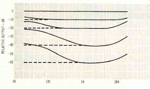
Fig. 6--Loudness-contour characteristics of the IC-150 at various settings
of the volume control with loudness circuits ON.

Fig. 7--IM distortion of the IC-150 as measured by the manufacturer. (Note
the expanded scale of percentages.)
We had no trouble plotting frequency response and tone control action (shown in Fig. 5), nor was filter response a problem (see same Fig. 5). Loudness contours are shown for various settings of the volume control when the "loudness" switch is depressed (see Fig. 6). We were able to measure hum and noise levels of approximately -93 dB below 2.5 volts output and equivalent phono noise (phono inputs shorted) at about .50 microvolts and to confirm RIAA equalization as being as close to perfect as our interpolation of fractions of a dB on our expanded scale a.c. VTVM would permit. However, when it came time to measure IM and THD, our test setup proved to be completely useless. As stated in previous reviews, we are rather proud of our new test equipment lower limits of 0.03% THD and 0.05% IM, but of what use are these new pieces of equipment when we are confronted with an IM figure (for 10 volts output) of 0.002%? In the interest of a complete report, however, we present Fig. 7, which is nothing more than a plot of the IM figures which appeared on the individual test sheet that accompanied our Model IC-150. Please read the scales carefully, as they are deliberately expanded beyond anything we normally show and, above all, feel free to take Crown's word for it, as we humbly do.
We shall reserve comment on our listening tests until after the discussion of the D-150 companion amplifier, since, as stated, all listening tests were done using both products hooked up together.
D-150 Power Amplifier
The D-150 dual power amplifier's optional front panel and walnut enclosure, again, need not be used except as dress items, since the power amplifier is fully enclosed as it comes and, in our view, somewhat more awe inspiring at that, as shown in Fig. 8. The major cover shown in the photo (which contains the serial identification label, etc.) is removable and, when removed, discloses the massive power transformer, as seen in Fig. 9. The photo also shows the pair of input jacks (phone jack type), above which are located a pair of screwdriver input level adjustments, and the speaker output terminals which utilize standard 3/4-in. center-to-center MDP terminals intended for the dual banana plugs normally associated with test equipment interconnecting cables. These are supplied in the accessory bag with each unit. Also included in the accessory bag are in-line fuse receptacles and cables which are strongly recommended as the right way to connect from amplifier output terminals to speaker systems, in the interest of speaker protection. A handy nomograph in the very complete instruction manual helps you to select the proper fuse size for your speakers based upon their impedance and their peak music power rating.
An "underneath the chassis" view of the D-150 is shown in Fig. 10 which discloses the driver and output transistors. Input stages and associated components are located on a p.c. board which cannot be seen in this view. The D-150 has two direct coupled amplifier circuits which employ a dual IC amp and silicon transistors in all amplifier stages. As Crown explains in their instruction booklet, the dual IC op-amp used is of extremely low noise type and has a large gain-bandwidth. As a result of its use as an input voltage amplifier, a maximum amount of feedback can be applied with resultant reduction of distortion to previously unattainable low values. At a typical full output of 75 watts (8 ohms), IM has been measured by Crown as 0.002%. By implication, THD might be expected to be approximately 0.0005% which neither Crown nor we could legitimately measure.
The output stages are essentially in a quasi-complimentary format. In this version of an output circuit, however, the driver transistors carry the bias current, while the output transistors serve only as boosters. The output transistors "sense" when the driver transistors are delivering significant current to the direct coupled loads and then takeover and deliver the required large load currents.

Fig. 8--D-150 amplifier with decorative panel and walnut enclosure removed.
Fig. 9--Close up of the D-150's power transformer and one filter capacitor.
Fig. 10--The D-150's entire chassis acts as a heat sink for the driver and output transistors.
The output circuit is protected by a V-I (volt-ampere) limiter which limits the drive to the output configuration whenever the output transistors are overloaded and acts instantly to relieve the overload, acting only so long as the overload exists.
In addition, a thermal switch is mounted on the chassis surface which protects the amplifier against insufficient ventilation.
If it becomes too hot, a.c. power to the amplifier will be interrupted until the temperature falls back to a safe level, at which time power is automatically restored. The excellently written and organized instruction manual details additional protection schemes which the user might incorporate external to the amplifier but these are primarily directed at speaker protection, since the amplifier itself is deemed "fail safe" under any conditions. Positive and negative power supplies (±45 volts) permit direct coupling to the loudspeaker and the voltage offset at the point of connection is guaranteed to be less than 10 mV. Filtering of each of the supplies is by means of a 9400 µF, 50 volt capacitor of massive proportions. The power transformer, incidentally, is suitable for 240 volt or 120 volt applications and is safe at any power line frequency from 50 Hz to 400 Hz.
D-150 Measurements

Fig. 11--Frequency response at 1 watt rms, 8-ohm load of the D-150.

Fig. 12--Power response, D-150.

Fig. 13--IM distortion characteristics, D-150. (Supplied the manufacturer.)

Fig. 14--Square wave presentations, A, output of IC-150 with 20 Hz applied;
B, output of IC-150 with 20 KHz applied; C, output of IC-150 and D-150 with
20 Hz applied, and D, output of IC-150 and D-150 with 20 KHz applied. (Note
that in all cases upper trace is signal source for comparison purposes to
output waveform in lower trace.)
Frequency response of the D-150 amplifier is plotted in Fig. 11. The-1 dB point (reference 1 watt, 8 ohm loads) was reached at 5 Hz on the low end and at 75 kHz at the high end.
Power response based upon 75 watts output per channel (clipping actually occurred at about 103 watts per channel, both channels driven, 8 ohm loads) extended to below any frequency we could measure (at 5 Hz, full power output was still obtained) and up to at least 30 KHz. A graph of this "straight line" is shown in Fig. 12. Hum and noise were measured at-120 dB with reference to 75 watts rms output, 8 ohm loads and is an unweighted reading (full 20 Hz to 20 kHz bandwidth). For those interested in startlingly small numbers, this means that the hum and noise power contribution to the loudspeakers is 75 x 10-'0 watts! (You may prefer to call this 75 pico-watts, or 0.000000000075 watts!) The real point is, YOU CAN'T HEAR IT-even with your ear glued to an efficient speaker system.
As for THD and IM measurements, we were again faced with the problem of test equipment. If Crown's claim of a theoretical THD of 0.0005% is correct (and we have no reason to doubt it), then we, along with Crown, have no way to measure it with presently available equipment. Evidently Crown does have an IM Meter capable of reading down to 0.001% and therefore presents a graph of IM versus power output which is reproduced in Fig. 13. Note that at 100 watts per channel into 8 ohm loads, IM distortion is approximately 0.005% and at 10 milli-watts power output (where any cross-over distortion would certainly show up if it were present), IM measured by Crown is just about 0.01%! A series of square wave photos were taken for both the IC-150 and the D-150 plus the IC-150 (operating together). These are presented in Fig. 14 with explanatory captions for each condition of measurement. The important thing to remember here is that the upper trace in each photo is our signal source while the lower trace is, in all cases, the output as observed from the IC-150 or the D-150. Thus, while not all the observed waveforms are perfectly "square," this arises from the fact that our source waveform is not always square either.
Notice, therefore, how closely the output always resembles the input waveform at all frequencies and conditions shown.
Fig. 15 simply represents the condition observed when the amplifiers are driven to clipping levels. At the moment the photo was taken, total power output was approximately 110 watts rms per channel and since both channels were being driven, the amplifier was pumping out about 220 watts of power into our purely resistive loads. Since our resistive loads used in all testing are rated at 100 watts each, we did not keep this up for more than the time required to set up the camera and take the 'scope photo.

Fig. 15--Scope photo of clipped 10 watt rms signal (per channel) from the
D-1 50 shows perfect symmetry of clipping and no evidence of "power
supply collapse."
Listening Tests
All our listening tests were done using the IC-150 and D-150 as an operating pair of components. Obviously, our speakers (which are low efficiency types selling at around $150.00 apiece) are the limiting factor in any listening tests using equipment such as this, but somehow, a new sense of transparency seemed evident. We know that this was not psychological projection because we brought in several experienced listeners who were not told the make or model of amplifier and preamplifier being used. Without exception, all these observers told us that these particular speakers (with which all were familiar) had "never sounded that good before. Now, we sincerely doubt if the IM figures of under .01% could be audibly interpreted as sounding better than, say 0.1% (which competitive equipment often achieves). Perhaps the unusually high damping factor (over 200 at all frequencies below 1000 Hz) was responsible for the audible difference. We're really not sure.
This much we do know, however: We monitored the signal delivered to our speakers and there were times when peaks of 90 watts were repeatedly delivered to the voice coil terminals. At all times the music was absolutely devoid of any audible distortion. We also discovered how important choice of source material becomes when you're dealing with equipment that is so perfectly "clean" in its reproduction capabilities. Evidently, less perfect amplifiers can often "mask" the deficiencies of certain types of poorly recorded material (we're speaking primarily of discs). There was, unfortunately, no single source of program that could fully utilize the dynamic range inherent in the IC-150/D-150 combination. That is, any signal source (FM, phono, tape) we tried invariably resulted in reproduced noise and/or hum that was greater than the inherent noise and/or hum which we didn't hear when listening to the equipment alone, with similar gain settings. If that sounds discouraging or suggests the question, "why buy something this good?", bear in mind that over the last decade, tape dynamic range, for example, has been improved by at least 10 dB or more. If such trends continue, it may not be long before you'll be able to feed a signal source to this superb preamplifier and amplifier that is as good as they are. If you want the very best control chassis and power amplifier we've ever tested in this power class and can afford the price, our endorsement of the Crown IC-150 and D-150 is completely given without any reservations (unless, of course, you feel you need MORE power, in which case there's always the Crown 300!)
-Leonard Feldman
(Audio magazine, Jan. 1972)
Also see:
Crown M600 Mono Power Amp (Nov. 1976)
Crown Power Line Four Amplifier (Apr. 1983)
Crown Macro Reference Amplifier (Equip. Profile, Jun. 1992)
Crown FM Two Tuner (Apr. 1982)
= = = =