What has widely been described as the "audio power race" began with the introduction, by U.S. Pioneer Electronics, of a new and very powerful receiver, their Model SX-1250, about a year ago. Not too long after that, Technics by Panasonic joined the race with their Model SA-5760. More than just "powerful receivers," both of these models offer a very high degree of control flexibility, a situation which suggests that the choice between a high fidelity system consisting of "separates" and one built around an all-in-one receiver is not as clear-cut as it once was.
Because these two receivers' specifications are so very close to each other, we decided to do a head to-head comparison test of the two units. However, during the course of evaluation, it became clear that when one deals with receivers in this price category, manufactured by two so-well-established names in high fidelity, a clear-cut, black and white verdict is not easy to reach. We are therefore attempting to give an objective, balanced report on the features and performance of each of these receivers, and let our readers use their own personal weighting systems to give relative importance to the features and performance, and thus decide for themselves which unit is the better. While the suggested retail prices of the two units differ by what seems like a substantial $100.00, as most readers are fully aware, the actual price you would have to pay for either of these receivers will depend upon the dealer with whom you do business, the amount of service provided by that dealership, the area of the country in which you live (some areas are noted for high discounts, others are not), and a host of other economic and business factors.
Front Panel Layouts
The front panel of the Technics SA-5760 has a large dial cutout, in which the actual frequency scales are printed against a light-colored, well-illuminated background, while the rest of the cutout area is framed in a contrasting dark background color. Within this dark area are framed to two tuning meters (signal strength and center of channel), as well as a series of function indicator lamps and the usual stereo indicator. A large tuning knob coupled to an effective flywheel tuning system is at the right, while at the extreme left of the darker area is an overload indication lamp which illuminates when the protection circuits have operated for any reason, such as the presence of a speaker short.
Calibration, on both FM and AM, is linear, with calibration marks provided for every half a Megahertz on FM. The lower section of the SA-5760 panel is equipped with a stereo headphone jack, located just below the power on/off pushbutton at the extreme left. Two speaker selector pushbuttons come next, followed by 11-position detented bass and treble controls which flank three pushbuttons. These last select bass turnover frequencies of either 250 Hz or 500 Hz, treble turnover points of either 2.5 kHz or 5 kHz, and defeat or bypass the tone control circuits when that is desired. Low- and high-cut filter buttons come next, followed by the balance control, and a 26-position attenuator type master volume control, calibrated in 2 dB steps from -40 to 0 dB. Five pushbuttons to the right of the volume control handle loudness circuits, 20-dB audio muting, FM muting, insertion of a sophisticated low-pass filter for FM tape recording (about which more later), and selection of stereo or mono listening mode. A rotary tape-mode switch comes next, with positions for tape monitoring of either of the two tape monitor circuits as well as copying from one deck to the other and vice versa. A rotary program selector switch comes next, and finally comes a phono impedance switch which selects 25k-, 50k-, or 100k ohm input impedance for both of the available sets of phono input circuits.
Pioneer's front panel is all light-colored, with frequency scales printed in dark letters upon a background color which matches the rest of the front panel. The FM frequency scale is linear, with calibration marks at every 200 kHz, while the AM scale uses the conventional non-linear frequency distribution. The two tuning meters are positioned above the center of these scales, while to either side of the meters are speaker indicator lights, stereo indicator, and program source indicating lights. A large flywheel-coupled tuning knob is located at the right.
Still within the framed dial area, and below the dial scales, are a series of pushbuttons, a phone jack, and microphone input jacks at the right. Three buttons take care of speaker selection, though only two sets of speakers can be selected at any given time. Two more buttons in this row take care of low and high frequency filter selection. The next two buttons take care of FM muting and selection of a circuit which permits you to audibly "tune" or orient your antenna for least multipath distortion on FM or stereo FM. The remaining five buttons in this group are used to select desired program sources. Microphone selection is made by depressing the Phono 2 button. When microphones are connected, the rear-panel phono 2 inputs cannot be used, though a second turntable may remain connected to them for use when the mike plugs are removed.
The lower section of the panel contains a power on/off switch, main and sub bass rotary controls, a tone-defeat toggle switch, main and sub-treble controls, balance control, and a master volume control with click-stop positions and calibration marks from 0 dB to-70 dB (plus "infinite attenuation"). All tone controls are also equipped with, fixed, repeatable, click-stop positions. Additional toggle switches interspersed between the rotary controls just mentioned include a loudness switch, a stereo/mono mode switch, a 20 dB audio muting switch, and four switches associated with the tape monitor and adaptor connection circuits found on the rear panel. One of these switches permits dubbing from one tape deck to another.
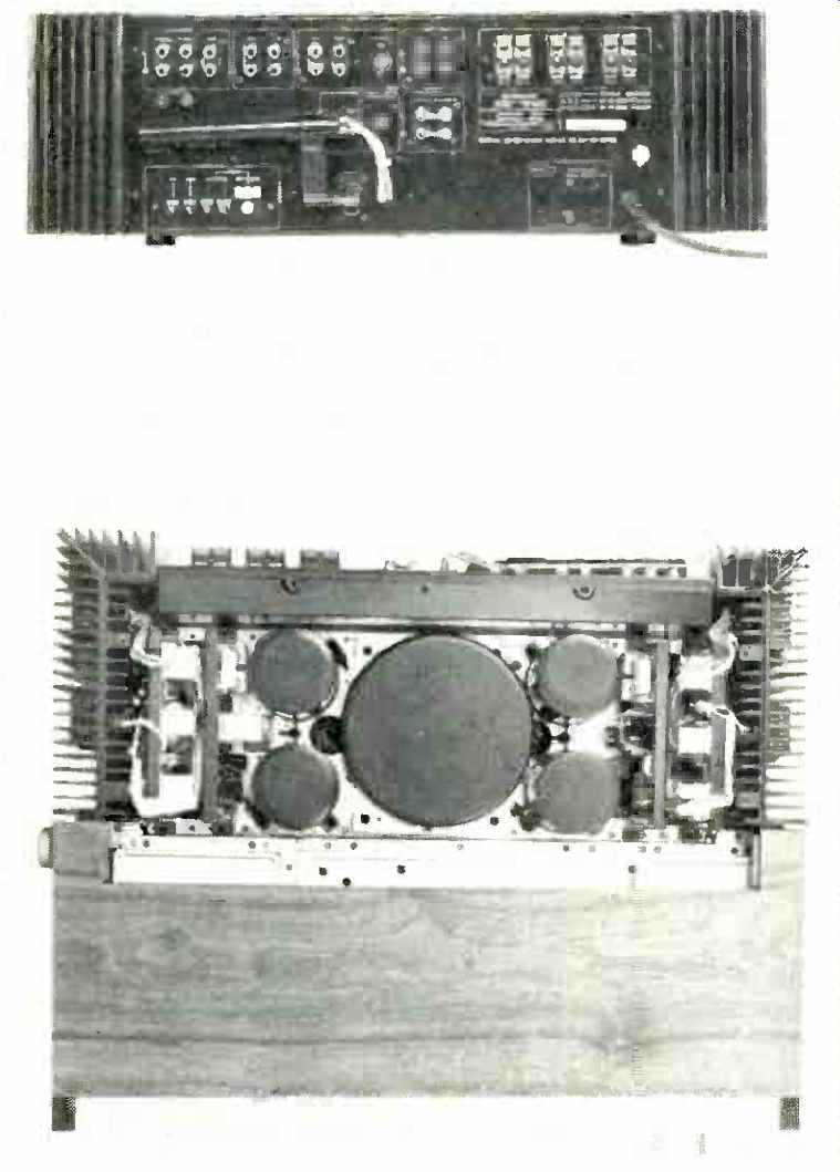
The rear panel of the Pioneer SX-1250 is equipped with input and tape output jacks (two sets of phono inputs are provided), and with an adaptor in/out combination of jacks that really constitutes a third "circuit interruption point" in the signal chain and is intended specifically for such add-on devices as noise reduction systems, expanders, graphic equalizers, etc. Ground terminals are located below the phono inputs. A DIN socket parallels the function of the Tape 2 in and out jacks. Spring-loaded speaker terminals permit connection of as many as three pairs of stereo speaker systems, though only two sets can be selected for listening at once.
Jumpers interconnect preamp outputs and power amp inputs and may be removed for separate use of these receiver sections. Antenna screw-terminals are provided for 75-ohm, 300-ohm, and AM external antennas. An FM-detector output jack is also provided for possible future use in connection with four-channel FM adaptors. A slide switch changes FM de-emphasis from 75 microseconds to 25 microseconds for proper Dolby FM listening (which requires the use of a separate Dolby decoder). One switched and two unswitched a.c. receptacles are located beneath the speaker terminals. A fully pivotable AM ferrite bar antenna near the antenna terminals completes the Pioneer rear panel layout.
Somewhat simpler in layout, the Technics rear panel has all its input and tape in/out jacks located at the lower left of the panel. Again, two sets of phono inputs are provided, as well as dual tape-monitor circuits. Antenna screw terminals for 75-ohm, 300-ohm, and external AM antennas are also located in this area of the rear panel, as are the pivotable built-in AM ferrite bar antenna and the four-channel "detector" output jack. At the opposite end of the rear panel are two a.c. convenience outlets (one switched, the other un switched), and two sets of spring-loaded speaker terminals which accept connections from "main" and "remote" pairs of speakers. A single ground terminal serves for both possible turntable grounds and for AM antenna ground return.
Circuit Highlights, Technics SA-5760
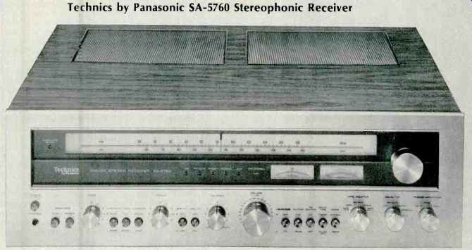
Above: Technics by Panasonic SA-5760 Stereophonic Receiver
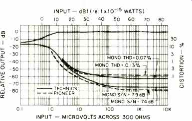
Fig. 1-Mono FM quieting and distortion characteristics for the Technics by
Panasonic SA-5760 and Pioneer SX-1250.
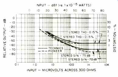
Fig. 2-Stereo FM quieting and distortion characteristics.
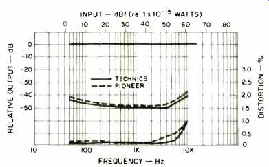
Fig. 3-Stereo separation and distortion versus frequency.
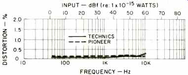
Fig. 4-Mono distortion versus frequency.
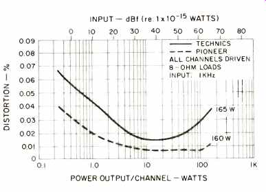
Fig. 5-THD characteristics (note expanded percentage scale).
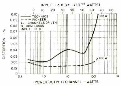
Fig. 6-IM distortion characteristics (note expanded percentage scale).
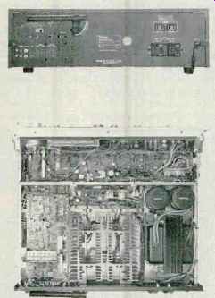
A view of the internal layout of the SA-5760 can be seen in the accompanying photo. A four-gang capacitor is used for FM tuning, while two additional gangs take care of the AM tuning circuits. Four-pole, dual-gate MOS-FETs are used in both the r.f. and mixer stages of the front end. The i.f. section (FM) uses six stages of differential amplification (combining three ICs plus discrete stages), along with two four element "flat group delay" ceramic filters. Control signal path (associated with the reed-relay operated, interstation muting circuit) is completely separate from the main i.f. signal path. A high-linearity ratio detector of Technics' own design provides the required linearity for low-distortion recovery of the composite stereo or mono audio signals.
Phase-locked-loop circuitry, combined with double-differential multiplex switching detection, is used in the stereo decoder section. The entire PLL circuit has been incorporated in an LSI IC. The audio stage, following the multiplex section, has been designed to withstand high levels of over modulation without introducing additional distortion.
The switch identified as Time Delay on the front panel activates a Chebyshev-type, low-pass filter for the elimination of sub-carrier output products. Interestingly, in our subsequent tests we were quite pleased to note that even when this sub-carrier rejection filter is inserted (as for taping FM programs, where high amounts of sub-carrier output beating with low-frequency tape bias oscillators might produce beats in the recording), frequency response of FM remained virtually perfect out to 15 kHz, while carrier leakage was attenuated practically down to residual noise level. In our opinion, Technics might well have left the filter in the circuit at all times, since response was so accurate with it in, but they obviously wanted to provide the option of perfect response to beyond 15 kHz for the purists who might object to a deviation from 75 µS curves by even a fraction of a dB at 15 kHz. All our tests were conducted with this special filter circuit in the "on" position, for with it off, sub-carrier outputs are too high in level (though, of course, inaudible) to make proper S/N and THD measurements. The AM circuitry is largely contained in a monolithic IC designed for that purpose, and includes a double tuned LC filter in the i.f. section.
The first stage of the preamp-equalizer circuitry is a differential amplifier with current-mirror load. A class-A amplifier follows, which in turn drives a single-ended, push-pull output circuit. Tone control circuitry consists of a three-stage, direct-coupled configuration with stabilized differential amplifiers in the first stage and single-ended, push-pull output circuitry in the final stage.
A differential amplifier is used as the first stage in each channel's power amplifier section, followed by emitter-follower stages. Pre-driver stages are constant-current loaded, class-A amplifiers, and a parallel push-pull design is used in the output stages, which are direct coupled. Power supply for the power stages features a pair of 22,000 mF capacitors for filtering the positive and negative voltages required in this output-capacitorless configuration. According to the manufacturer, the power transformer in this receiver alone weighs 22 lbs-and from the looks of it, we have no reason to doubt the figure.
Three forms of protective circuitry are incorporated in the SA-5760. A current limiter is activated in the event of a speaker short (or if load impedance drops below 2.0 ohms), and a relay opens, disconnecting speakers loads and lighting the front-panel alarm light. If a d.c. voltage (or a very low frequency a.c. signal) appears at the output, relays switch off all speakers, thereby protecting them. In addition, a five second delay upon turn-on prevents "pop" noises in the output, permitting all voltages to stabilize before sound is heard.
Circuit Highlights, Pioneer SX-1250
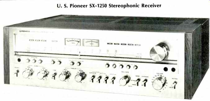
Above: U. S. Pioneer SX-1250 Stereophonic Receiver
Three dual-gate MOS-FETs are used in the front end of the SX-1250 (two in the r.f. amp section, one for the mixer). A five-gang variable capacitor is used for FM tuning, while a three-section capacitor is used for the AM section. The front end and the i.f. sections are both shield-covered, as can be seen in the accompanying photo. Four two-element, phase linear ceramic filters are used in the i.f. section. Active elements include two ICs for the differential amplifier and a large-scale integrated circuit. The stereo multiplex decoder section uses a phase-locked-loop circuit IC, along with a three-element, low-pass filter which reduces carrier products at the output. FM muting is accomplished by means of a reed-relay. AM circuitry is largely contained in a single IC. A three-stage, direct-coupled, single-ended, push-pull circuit in the preamp-equalizer section uses a dual polarity supply and a differential amplifier. Output stage of this section operates in the class-A mode. Dual polarity voltages are used in the tone control section supply. The tone control section also includes a class-A circuit as the input-buffer amplifier and a flat amplifier which employs an FET. As for the power amplifiers, they employ a two-stage, class-A, differential amplifier, push-pull circuit with a current-mirror circuit in the pre-driver stage. A three-stage, Darlington, direct-coupled circuit is used in the driver stages, followed by a parallel push-pull circuit in the output stages. A toroidal core power transformer has separate windings for the two stereo channel supplies, each of which is filtered by a pair of 22,000 mF capacitors.
Protection circuitry in the SX-1250 includes a power relay which helps prevent damage to speakers or transistors from power-related mishaps. The relay, located in the primary circuit of the transformer, helps to reduce the amount of inrush current which would normally flow when the unit is first turned on. Heat sinks are located along the sides of the unit, near the rear of the receiver, and each is thermally connected to its appropriate and separate power amplifier module.
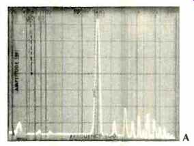
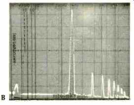
Fig. 7--Harmonic content of 1-kHz output signal, with receiver driven to clipping
(0.5% THD). A is Technics SA-5760, B is Pioneer SX-1250. Large peak is fundamental
1-kHz signal; peaks at right are harmonics. One vertical division is 10 dB.
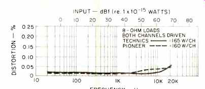
Fig. 8--THD versus frequency (note expanded scale).
FM Performance Measurements
Major monophonic performance characteristics of the FM sections of the two receivers can be compared by examining Fig. 1. IHF sensitivity was identical for both units (1.8 µV, or 10.3 dBf) as against the greater claim made by Pioneer, 1.5 µV (8.7 dBf). The 50-dB quieting point was reached with a signal input of 4.0 µV (17.23 dBf) in the case of the Technics receiver, 3.3 µV (15.6 dBf) for the Pioneer unit.
Mono THD reached a low of 0.13 percent on the Pioneer, 0.07 percent for the Technics receiver. Best S/N in mono was 74 dB for Technics, 79 for Pioneer.
Referring to Fig. 2, best stereo S/N measured 70 dB for the Technics unit, 75 dB for the SX-1250, while THD in stereo (at 1 kHz) measured 0.15 percent for both tuner sections. The 50-dB stereo quieting point was reached with a signal input of 30 MC (34.7 dBf) for the Pioneer, 33µV (35.6 dBf) for Technics. Capture ratio measured as claimed for both units (1.0 dB). Selectivity was exactly the 83 dB specified for the Pioneer, while in the case of the Technics it measured 82 dB, a bit better than claimed. We could not confirm readings for image, i.f., or spurious response rejection in the case of the Pioneer, since our measurement capability is limited to a 100 dB maximum for these specs. The i.f. and spurious rejection for the Technics unit measured at least 100 (again limited by our test equipment), while image rejection measured 85 dB, as claimed. AM suppression for both units was approximately 60 dB, as claimed.
Muting threshold for the Technics unit was set at 5.5 µV (20 dBf), while in the case of the Pioneer model muting threshold was measured as 2.4 MV (12.8 dBf). Switching from mono to stereo took place with an input signal strength of 5.0µV (19.2 dBf) for the Technics receiver, while 2.2 µV (12.0 dBf) was required for the Pioneer. Stereo usable sensitivity for the Pioneer measured 3.3µV (15.6 dBf), 4.0µV (17.2 dBf) for the Technics model.
Figure 3 compares stereo separation and stereo distortion for the two FM tuner sections and shows the Technics receiver as having slightly greater separation and slightly lower THD in stereo over most of the audio frequency band measured. In Fig. 4, a plot of mono THD versus frequency, results are extremely close, though this time Technics is slightly ahead except at the extreme high-frequency end of the spectrum measured (10 kHz). On our test samples, calibration of FM on the Technics model was just about perfect, while in the case of the Pioneer unit, calibration was off by anywhere from 0.3 Mhz to 0.5 MHz, with worst error at the low end of the dial.
Amplifier Measurements
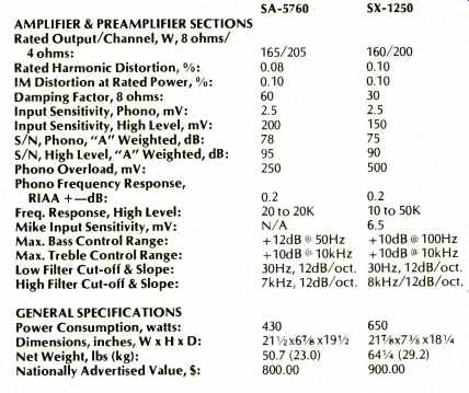
The power amplifier sections of each receiver easily met published specifications with regard to rated power output and harmonic distortion. The Technics unit delivered 188 watts per channel before the rated value of 0.08 percent THD was reached, using 8-ohm loads, both channels driven, while the Pioneer delivered 180 watts per channel for its rated THD of 0.1 percent. Figure 5 compares measured harmonic distortion within the specified FTC power range from 0.25 watts to full rated output. Note that the vertical axis has been vastly expanded in this figure (compared with our usual graphs of these characteristics in other test reports), so that the minute differences in distortion between the two units can be read and interpreted. In like manner, Fig. 6 compares IM distortion readings at relevant power levels for both receivers and, in this instance, differences are somewhat greater, particularly at the rated power of each receiver, where the Technics unit made its published specification of 0.1 percent, while the Pioneer unit did considerably better than claimed. Bear in mind that we are dealing with ultra-minute figures in both cases, since even at full output, rated IM is listed at 0.1 percent for both receivers.
In an attempt to learn of any further differences between the power output section of each receiver, we next increased the power output of each until a THD reading of 0.5 percent (well beyond clipping) was reached. Each output signal was analyzed by means of our spectrum analyzer which displays the various harmonics present in the output signal under these conditions. Figure 7A is a scope photo of the results obtained using the Technics receiver and shows even as well as odd harmonics present. Under the same test conditions, and with gain settings the same, the analysis was repeated for the Pioneer unit (Fig. 7B). We noted here that amplitudes of fifth, seventh and ninth harmonics were somewhat higher, but there were no significant contributions of even order (second, fourth) harmonics in the case of this receiver. Thus, while both receivers measured 0.5 percent THD for this "clipping" condition, the composition of the distortion components is seen to be quite different between them.
Figure 8 compares harmonic distortion at full rated output (160 watts for the Pioneer, 165 watts for the Technics) at different frequencies, and any differences observed are primarily at the high end of the audio spectrum, where audible significance is doubtful.
It should be noted that since each manufacturer quoted power output ratings for 4-ohm operation, as well as 8 ohm, we did measure power output capability for these lower-impedance loads. Under 4-ohm loads, the Pioneer unit delivered 245 watts per channel for 0.1 percent THD, while the Technics delivered 210 watts per channel for 0.08 percent THD, both well within spec. IM distortion at rated output (4 ohm loads) for the Technics unit was a bit higher than that for the Pioneer at its rated output, but the differences were rather insignificant in our opinion.
Preamplifier and Tone Control Sections
Phono input sensitivity for both units were within fractions of a millivolt of each other, with 2.2 mV (for full output) measured for the Pioneer and 2.4 mV for the Technics receiver. Overload in phono (at 1 kHz) occurred with an input signal of 560 mV in the case of the Pioneer, 260 mV for the Technics, both well beyond published specifications.
RIAA equalization was accurate to within 0.2 dB on both units from 30 Hz to 15 kHz, as claimed. The "A" weighted hum and noise in phono measured 78 dB for the Technics unit, 73.5 dB for the Pioneer. In high level service, hum and noise below rated output measured 85 dB for Pioneer, 92 dB for the Technics, while at minimum volume, residual hum and noise was down 98 dB below full output for the SX-1250, 95 dB for the SA-5760. Frequency response in which level inputs extended within 1 dB from 10 Hz to 53 kHz for the Pioneer unit, 10 Hz to 57 kHz for the Technics model. The microphone input on the Pioneer (Technics does not include a mike input on their model) had an input sensitivity of 5.0 mV for full output.
Pioneer and Technics deal with the problem of tone control flexibility in different ways. The Technics unit provides two turnover frequencies for both their bass and treble controls, while Pioneer offers separate "main" and "sub" bass and treble controls. In Fig. 9 we see a plot of the range of the Technics bass and treble controls when the turnover points are set to 500 Hz and 2.5 kHz (Fig. 9A), while in the case of the Pioneer, curves obtained using only the "main" bass and treble controls are shown in Fig. 9B. A second comparison of tone control action is shown in the scope photos of Fig. 10.
In this presentation, the 250 Hz and 5 kHz turnover points were selected for the Technics model (Fig. 10A), while in the case of the Pioneer unit (Fig. 10B), the "sub" or secondary control action was plotted. It should be noted that additional tone control ranges and settings can be obtained for the Pioneer unit by combined use of the main and sub tone controls, whereas in the case of the Technics model, either low frequency turnover could be used with either high frequency turnover setting to create additional overall response range or tone control action.
Low- and high-cut filter response was plotted for both receivers, and results are shown for the Technics SA-5760 in Fig. 11A, while those for the Pioneer unit are displayed in Fig. 11B. Cut-off points and slopes are virtually identical for both receivers.
In the case of loudness control action, Technics elected to provide increasing bass compensation at progressively lower volume settings, while Pioneer opted for both bass and treble compensation as the volume control is lowered with the loudness circuitry selected. Plots showing response of these circuits from full volume (0 dB) to -50 dB are shown in the scope photos of Fig. 12A and 12B.
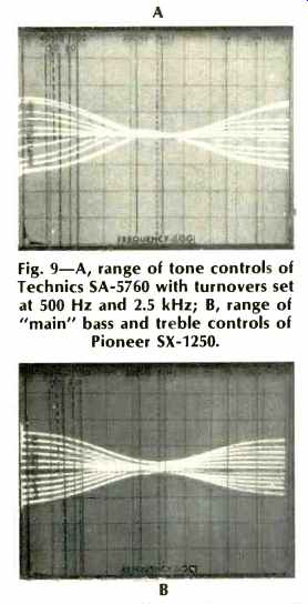
Fig. 9--A, range of tone controls of Technics SA-5760 with turnovers set at
500 Hz and 2.5 kHz; B, range of "main" bass and treble controls of
Pioneer SX-1250.
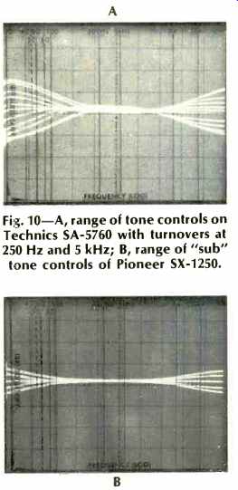
Fig. 10--A, range of tone controls on Technics SA-5760 with turnovers at 250
Hz and 5 kHz; B, range of "sub" tone controls of Pioneer SX-1250.
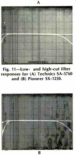
Fig. 11--Low- and high-cut filter responses for (A) Technics SA-5760 and (B)
Pioneer SX-1250.
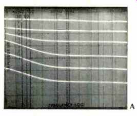
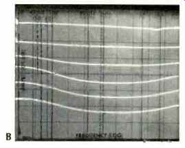
Fig. 12-Loudness control action for (A) Technics SA-5760 and (B) Pioneer SX-1250.
Using and Listening to the Receivers
When one considers the number of controls and features available at the front panels of both the Pioneer SX-1250 and the Technics SA-5760, one cannot but admire the formidable engineering talent that went into the design and layout of each of these products. The similarities in function are greater than the differences, but some differences do exist. The multipath audible-null feature, present on the Pioneer, is a useful feature and helps to orient FM outdoor antennas for best reception. On the other hand, the tape monitor/duplicate switching arrangement on the Technics panel is easier to use and easier to understand with its clearly noted separate positions (on a rotary switch) for dubbing or monitoring. The microphone inputs on the Pioneer, not available on the Technics model, may appeal to some users, though the chief advantage (in our opinion) of having mike inputs on a central component, namely being able to mix mike with other program sources, is not possible on the SX1250. Controls on both units are silky smooth and precise, especially those multi-detented master volume controls.
Need we mention that either receiver provides ample audio power for just about any loudspeaker system you might choose to use with it? In our listening tests you can bet that we were not able to drive either receiver into audible clipping to do so would have left us with a pair of destroyed speakers, we suspect, since the ones we used to listen with were rated at 100 watts). While the Technics unit lacks the switchable de-emphasis feature of the Pioneer SX-1250, inexpensive outboard adaptors are available for making this transition, should you wish to add a Dolby decoder to your system in' order to properly listen to any FM Dolby broadcasts in your area. Such an adaptor will just as easily plug into one of the two available tape monitor circuits of the Technics unit as into the specially labeled "adaptor" jacks included on the Pioneer SX-1250, though of course that would preclude permanent connection of two tape decks in the case of the SA-5760. After much listening to available FM signals in our area, we could frankly detect no difference in program quality when heard using either of the two receivers, which suggests that both of them are probably being limited by existing station practices and program quality. As for phono reproduction, it was tight and uncolored in both cases, with no evidence of overload even when the most dynamically recorded discs we own were played. The phono impedance selector on the Technics unit does offer a means for changing high-end response of some cartridges to suit individual listening tastes and would also provide a proper "match" if you happen to own a CD-4 cartridge that you are using for stereo purposes.
As we suggested at the outset, our main purpose in evaluating these two high-powered receivers was to describe and measure the performance of two remarkable products which would have been impossible to produce just a few short years ago. Most readers will clearly remember when receivers broke through the "100 watt per channel" barrier (it wasn't all that long ago), and here we are with a well-designed, excellently styled pair of receivers which, in four ohm load operation, actually deliver more than double that amount of power per channel.
Those of our readers who judge the merits of a product strictly on "specs" can have a field day rereading the two manufacturer's published specifications as well as the figures obtained in our one-sample-of-each measurements and studies. Other, less technically concerned readers, interested in owning a high-powered receiver such as the Pioneer SX-1250 or the Technics by Panasonic SA-5760, would do well to audition both units in person, to evaluate their own response to control features by hands-on operation of each.
-Leonard Feldman
(adapted from Audio magazine, Jan. 1977)
Also see:
A/V Receiver Roundup (Dec. 1992)
= = = =