
SHIFTY CHARACTERS
Let's continue last month's discussion of filtering, and focus specifically on the workings of digital filters. As we have observed, the analog output signal of a CD player is a pulse-amplitude-modulation waveform. The ultrasonic content of the signal is a series of image spectra which are duplicates of the original spectrum.
It is the anti-imaging filter's job to remove these duplicate images, leaving only the original spectrum. The summation of a low-pass filter's sin(x)/x responses to those individual impulses reconstructs the signal's waveform.
Rather than use an analog brick-wall filter to suppress ultrasonic image components after the signal has been converted to analog form, it is possible to process the digitized signal before D/A conversion, using a digital filter.
The underlying mechanism used in a digital filter is time delay. Surprised? Don't be. Delay can profoundly affect both analog and digital signals.
For example, a delayed analog signal added back to itself results in a wholly new frequency response-creating a comb-filter response. If a signal is delayed by time T and mixed with the original undelayed signal, cancellations will occur at odd multiples of the frequency f = 1/(2T). For example, a 1-mS delay will produce notches at 500 Hz, 1500 Hz, 2500 Hz, etc. This filtering technique produces no phase distortion whatsoever.
Briefly, this is what happens in a digital audio filter: Each input sample is multiplied by the sin(x)/x coefficient corresponding to its contribution to the filter's overall impulse response. The delayed multiplication products are summed together to produce the "filtered" output sample. Thus, the impulse response of an analog filter is digitally simulated. Let's consider a digital filter's operation in more detail.
Each sample point of a digitally filtered output signal is the sum of many filtered samples from just before and just after the sample point in question.
Such time shifts require a delay line.
Since the samples are digital, we may use a shift register with output taps after each delay element, as shown in Fig. 1. Input samples enter the shift register, the output of each tap is multi plied by a coefficient associated with the impulse response, and the product is summed with other products to yield the new output sample.
From a spectrum standpoint, the multiple delays yield overlapping notches in which all frequencies are attenuated. In a CD player's digital filter, the delays are specifically calculated to attenuate image spectra above the audio band.
The sum of many such multiplied samples yields low-pass filtered data.
To access many such samples, each time a new sample is input, the samples in the shift register are shifted one delay to the right, and the new sum of products is recalculated. Because of the movement of the samples across the shift register, this design is often called a transversal filter.
To recapitulate (and referring again to Fig. 1), assuming that data has al ready shifted through the filter, the T1 output sample is equal to the T1 input sample times the C1 impulse response coefficient, plus the T2 input sample times the C2 impulse coefficient, plus the T3 input sample times the C3 impulse coefficient, plus the T4 input sample times the C4 impulse coefficient. When the next new sample is entered, the previous samples are shifted one delay to the right to make room for it, and the calculation is repeated. In this example, each sample shifted through the filter requires four multiplications and four additions.
In practice, a number of considerations determine the design of an implemented filter. The analog signal is the sum of the sin(x)/x waveform resulting from each sample. The sin(x)/x waveform extends to infinity in both the positive and negative directions, so theoretically all of the values of that infinite waveform would be required in order to reconstruct the analog signal.
(In our example above, only four coefficients were used.) Fortunately for de signers of digital filters, we can find a point on the waveform where neglecting any further response results in a negligible error; a filter which disregards the response values beyond such a point is called a finite impulse response (FIR) filter. In some implemented FIR designs, perhaps 24 or 30 samples are summed.
The technique is almost successful; however, when a time delay is used, the signal is mixed with delayed copies of itself, spread over time. To perform this calculation without audible aliasing, the filter must operate at a rate faster than the disc's 44.1-kHz sampling rate. Additional samples must be created; this technique is often called oversampling.
An oversampling digital filter uses samples from the disc as input, then computes additional samples. Because additional samples have been generated, the sampling rate of the signal is greater (perhaps two or four times greater) than it was originally.
To achieve this oversampling, a transversal filter (an inefficient one, as we shall see) could be constructed so that each delay is one-quarter the sampling period. This would result in four times the number of output samples, with the filter calculating three new values for each input sample. This avoids aliasing. To provide enough impulse-response values to permit a good response after summation, perhaps 96 delay elements would be required.
In each sample period, the shift register would input new data four times, but only every fourth sample would be audio data from the disc. The other three intermediate samples would be zero, to reserve places for the extra values to be calculated a bit later.
Thus, only 24 of the 96 filter elements would contain non-zero data at this time. The filter would output data at a rate of 176.4 kHz, each new sample being the sum of 24 non-zero multiplications. The filter thus would calculate three new sample values at the locations of the zero input samples. however, this oversampling design is inefficient; the same result can be obtained with fewer delay elements.

Fig. 1 A transversal filter uses a shift register, coefficient multipliers,
and adders to produce a filtered output.

Fig. 2 A practical four-times oversampling transversal filter using 24 delay
elements and four sets of coefficients.
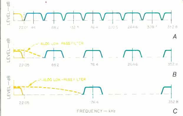
Fig. 3-The D/A converter's "staircase" output originally contains
an infinite series of images of the original signal's audio-band spectrum (A).
Digital filtering, with oversampling at two times (B) or four times (C) the
original sampling frequency, suppresses the images immediately above the audio
band. The remaining images are easily filtered out.
A more cost-effective approach is seen in Fig. 2. It shows the architecture of a practical four-times-oversampling digital filter, generating three intermediate samples between each input sample. The filter consists of a shift register of 24 delay elements, each delaying a 16-bit sample for one sampling period. Thus, each sample re mains in each element for an entire sample period. During this time, each 16-bit sample is multiplied four times by 12-bit impulse-response coefficients stored in ROM, with a different coefficient used for each multiplication. In total, the four sets of coefficients are applied to the samples in turn, producing four output values per sample. The 24 multiplication products are summed four times during each
period, and the summed products be come the output from the filter. The data is shifted one place, and the pro cess is repeated. Four times as many samples are present after oversampling, with new intermediate values calculated by the transversal filter.
Therefore, the sampling frequency has effectively been increased four times, to 176.4 kHz.
In summary, as the 16-bit audio samples pass through the filter, the samples are delayed by each of the 24 elements. As a result, after multiplication by the 12-bit coefficients and summation, the weighted average of a large number of samples is generated.
The values of the intermediate samples, obtained by the calculation pro cess, determine the filter characteristic; the bands centered at 44.1, 88.2, and 132.3 kHz have been suppressed, as shown in Fig. 3. These broad regions of suppression are the overlapping filter notches referred to earlier.
Our filtering goal, removing the image spectra from the vicinity of the audio band, is accomplished.
After the multiplications involved in oversampling, the word length is much longer than the original 16 bits. however, the output word cannot simply be truncated to 16 bits; this could increase distortion. A special rounding-off process, known as noise shaping, is sometimes employed. With noise shaping, a 16-bit digital filter can yield a dynamic range equivalent to that of an 18-bit system. Alternatively, some manufacturers employ those extra bits for bit-shifting, selecting the input to a 16-bit D/A converter from these 18 bits.
Following the digital filter, the data is converted back to analog with a digital-to-analog converter. Finally, the remaining band around 176.4 kHz (in the case of four-times oversampling) must be completely suppressed by an analog filter. This filter follows the converter, just as in players without digital filtering, but it is tame compared to brick-wall filters. Since the remaining band is so high in frequency, we can use a filter with a gentle, 12 dB/octave response and a -3 dB point between 30 and 40 kHz. It is a noncritical de sign, and its low order guarantees good phase linearity; phase distortion can be reduced to ±0.5° across the audio band.
In this example, we have focused on a four-times oversampling circuit.
Many CD players use two-times digital filters, in which the 44.1-kHz sampling rate is oversampled to 88.1 kHz. In such systems, the spectrum centered around 88.2 kHz is prominent and must be filtered out. Because this frequency is closer to the audio band, a sharper analog low-pass filter is required. For example, in some two times oversampling players, a sixth-order analog filter is used.
A digital filter design is thus an efficient method of accomplishing the task of anti-imaging without resorting to analog brick-wall filters. It alleviates the problem of phase distortion introduced by analog filters. A digital filter, as found in Compact Disc players, can have almost perfect linear phase response.
But what about digital audio recorders? What good is perfect phase linearity at playback, when every disc contains phase nonlinearity introduced by the brick-wall anti-alias input filters of the digital recorder? Well, oversampling can be used for input filters as well. But that's another story.
(adapted from Audio magazine, Jan. 1988)
= = = =