

Fig. 1-Frequency response, left (top) and right channels, with Digital Time
Lens off.

Fig. 2-Same as Fig. 1 but treble dips are 2.1 to with Time Lens on. Bass
2.3 dB at 3.1 kHz. Note peaks shown measure also treble peak just +2.3 to
+2.4 dB at 145 Hz, below 20 kHz.

Fig. 3--Spectrum analysis, 0 Hz to 50 kHz, showing 20-kHz tone (tall spike)
and spurious beat tone (small spike) at 24.1 kHz.

Fig. 4--THD vs. frequency at three signal levels.
= == =
Manufacturer's Specifications
Frequency Response: 5 Hz to 20 kHz, ±0.5 dB.
S/N Ratio: 96 dB. Dynamic Range: 96 dB.
Channel Separation: 60 dB. THD: 0.05% at 1 kHz.
Output Level: 1.9 V at 0 dB.
Number of Programmable Selections: 99.
Power Consumption: 26 watts.
Dimensions: 19 in. (48.3 cm) W x 3 7/16 in. (8.7 cm) H x 11 1/4 in. (28.6 cm) D.
Weight: 13 lbs. (5.9 kg).
Price: Approximately $649.
Company Address: 19210 33rd Ave. West, Lynnwood, Wash. 98036, USA
= == =
Leave it to Bob Carver to come up with a CD player designed to please both those who love CDs and those who still have reservations about their sound quality. Carver, one of the true innovators in the audio industry, has given us such "magical" signal-processing circuits as the Auto-correlator (a single-ended noise-reduction circuit), Sonic Holography (a space-expanding stereo system), Magnetic Field Amplification, the Asymmetrical Charge-Coupled FM Stereo Detector (for better FM stereo reception), and now, the Carver Digital Time Lens, intended to satisfy those who maintain that LPs sound better than CDs. The names o these audio innovations don't tell you much about what the circuits actually do. The fact is, though, that these circuits do what Carver intends, and they do it very well indeed. His newest, the Digital Time Lens, is no exception. But before get into that unit in detail, let's have a look at the way Carver has put together his first CD player, which, like his receiver, carries no model number-only the appellation The Carver CD Player (emphasis mine).

Fig. 5--S-N analysis with Digital Time Lens adding dither, both unweighted
(A) and A-weighted (B).

Fig. 6--Unweighted S N analysis, without added dither.
Control Layout
The player's front panel conforms in size and color to several other Carver products, featuring a 19-inch-wide front panel equipped with handles and finished in a subdued charcoal gray. Carver continues to insist upon using what I call "black on black" printed nomenclature on his front panels. It's almost invisible unless light his the panel a just the right angle. For a reviewer such as myself, this can be frustrating at times, as I strain to find the right buttons to push. However, for an owner of the equipment, who be comes accustomed to the various controls' positions, i should pose no problem. In fact, it makes for a very subdued-looking panel which fits in with home decor much better than some of the garishly inscribed panels I have seen.
Other than the two handles, there are no protrusions on the front panel whatever. The CD drawer at the left is opened by touching a square touch pad on the right of the drawer; it's closed either by touching that button a second time or by touching the drawer itself. The on-off button is located below the disc drawer. A pushbutton below the "Open/Close" button activates Carver's Digital Time Lens (about which I will have much more to say in a few moments). When the "Digital Time Lens" button is depressed, a light above it indicates that this circuit is in use. An LED display near the panel's center alternately displays track number or elapsed time within the track. When a disc is loaded into the disc drawer, the display first shows the total number of tracks on that disc and can then be switched to show total time on the disc. When you're programming, the display shows both the current track or index number and the current program slot--i.e., "16P 3" indicates that you've programmed track 16 as the third of the 99 possible program selections.
Although the display is really a simple numeric one, Carver has managed to program the eight-segment LEDs so that they also provide useful "alpha"-type data. When power is first turned on, the laser pickup does some searching, while the display blinks with a few dashes ("----"). If no disc is located, the word "dISC" begins to flash intermittently. When the door is opened, the word "OPEn" appears.
After your programmed selections have been played, or the programming is completed, the word "End" appears. Below the display are three small pushbuttons, labeled "Display" (for switching between elapsed time and track number), "Program" (for initiating program mode and storing each of the track numbers to be played) and "Repeat" (for programming repeat-play of a given disc or group of tracks that have been selected). Six more touch pads or buttons, to the right of the display, initiate play, track-by-track reverse or advance, stop/pause, fast-reverse and fast-forward (with muted but audible cueing). The track-by-track and cueing buttons are clustered in a square, for convenient shuttling between tracks and locations. These buttons have auto-repeat, so if you wish, for example, to jump ahead by 40 tracks, just hold down the track-advance ("+") button. The display will show track numbers advancing faster and faster until you lift your finger-"warp drive," Carver calls it, though slewing is more usual.
Loading a disc in the drawer and pressing "Play" will close the drawer and start the player. If you press "Open/ Close" instead (or simply nudge the drawer itself), the drawer will close and the player will scan the disc to locate its tracks, but play will not begin until you press the "Play" button.
You can begin programming a disc even before the drawer has closed. Press the "Program" button to get into the mode, then press the "+" button to advance to the desired track. If you overshoot, just press the "-" button.
(The forward and reverse buttons perform the same functions, but for index points, not tracks.) Pressing the "Program" button once again stores your selection, blanks the left (track/index number) side of the display, and changes the right side from "P 1" to "P 2" for your next selection.
There is no output-level control and no headphone jack.
The rear panel carries only the usual pair of output jacks and the power cord.

Fig. 7--Square-wave reproduction, 1 kHz.
Measurements
Because of the Digital Time Lens in this CD player, some of my usual measurements had to be taken twice. For example, Fig. 1 shows the normal frequency response of the player without the addition of the special circuit. It is flat to better than ± 1.0 dB to 20 kHz. The vertical scale in this graph and in Fig. 2 has been expanded to 2 dB per division, to show even slight deviations from flat response. Figure 2 shows what happens to the response when the Digital Time Lens is switched in. Note that the equalization circuit adds a bit less than 2.5 dB of boost at 145 Hz and just over 2 dB of treble cut at 3.1 kHz.
Harmonic distortion at mid-frequencies, for maximum recorded level, measured 0.0045%, rising insignificantly to around 0.006% at the bass and treble frequency extremes.
==========
THE DIGITAL TIME LENS--THEORY AND PRACTICE
Bob Carver, along with many others, was displeased by the sound of the earliest CDs and decided to find out why some didn't sound the same (or, some say, as good) as the LP versions of the same recordings. Unlike many who have complained about poor stereo imaging, lack of depth and strident, harsh treble and who have blamed the CD digital system itself-Carver was enough of a mathematician and engineering theorist to know that the system itself was inherently blameless.
After extensive comparison tests between LPs and their CD versions, which included time-synchronized playings of both types of record while measurements and observations were made, Bob Carver concluded that there were two major differences between certain CDs and their LP equivalents. The first had to do with stereo depth or separation. In any stereo program, the stereo effect is transmitted by the difference between left and right signals (L R), while the sum of the two signals conveys the mono information. Bob discovered that many CDs have less relative L-R information (compared with the quantity of L + R signal) than do the LPs of the same programs, at the same musical moment.
This difference is not great-often no more than 1 dB or so. In fact, in order to see it on an oscilloscope, Carver had to devise a special test circuit that would amplify the difference. A block diagram of that test circuit is shown in Fig. B1, just in case more ambitious readers want to duplicate Carver's experiments. The four-quadrant multipliers in Fig. B1 expand the output voltages instantaneously so that the Lissajous patterns obtained by connecting the left and right outputs to the vertical and horizontal inputs to an oscilloscope will be easier to interpret. The differences in patterns obtained are, in effect, raised to the second power and become proportional to the output power (rather than voltage) or energy into the listening room. (The matrix and de-matrix blocks in the diagram represent M-S encoding and decoding matrices.)
The next two figures show the Lissajous patterns obtained from the same instant of musical program in its LP (Fig. B2) and CD (Fig. B3) versions. In this type of Lissajous display, a straight, thin, diagonal line from the lower left to the upper right would represent a purely monophonic signal. The more stereo "difference" information there is, the more the line spreads out into an ellipse.
Notice that there is significantly more difference (L R) signal in the LP version of the music!
The second major difference between some CDs and their LP counterparts noted by Carver during his research was a difference in equalization, or the overall frequency response. Using a fine moving-coil cartridge to play the LP versions of certain programs, Carver noted that there was a slight boost in the mid bass region and a slight cut in the mid-treble region compared with the response obtained when playing the CD version of the same program. The average difference is shown in Fig. B4, where the straight-line response is arbitrarily taken as the response of the LP version, while the other curve shows the response of the CD relative to that reference response.
Carver's objective in designing the Digital Time Lens was to give the user the ability to introduce the converse of these two effects, at will.
That, essentially, is what he has done: If there is a deficiency of L R signal in some CDs, the user can interpose a form of matrix-de-matrix circuitry that will put back some extra L R signal. If there is overly bright mid-treble and somewhat diminished mid-bass in a CD, the user can add a little mid-bass and attenuate some mid-treble frequencies by means of a switchable circuit. The important thing about the Digital Time Lens, as Carver points out, is that it is switch able. There are some CDs that will not benefit from its use (says Carver) since they are recorded well and are musically pleasing. For those that do require the kind of compensation that the circuit provides, The Carver CD Player lets you introduce it. A block diagram of the Digital Time Lens circuit is shown in Fig. B5.

Fig. B1--Block diagram of circuit used to emphasize and view changes in
L - R)/(L + R) ratios.

Fig. B2-Lissajous pattern showing (L R)/ (L + R) ratio from an LP record.

Fig. B3-The same instant of music as in Fig. B2 but taken from the CD version.
Note the decreased difference (L R) content, as shown by the narrowed trace.

Fig. B4--Relative frequency response of a recording in its CD (lower trace) and LP (upper trace) versions, using the LP as a reference arbitrarily assumed as "flat."

Fig. B5--Block diagram of the Carver Digital Time Lens.

Fig. B6--Ultra-low-level (4-bit), 1-kHz signal, as reproduced by conventional
CD players.

Fig. B7--Same as Fig. B6, with dither added before D/A conversion.
There is one "block" in Fig. B5 that I haven't talked about yet, the one labeled "Random-Noise Dither Signal." Carver admitted to me that he is not sure whether this feature of his Digital Time Lens really provides an audible benefit, but he could easily demonstrate its theoretical desirability. (See also "Digital Domain," Audio, November 1984.) Without dither, very low-level signals are subject to very high distortion. Take, for example, Fig. B6, which shows the output of The Carver CD Player reproducing a 1-kHz signal at 90 dB below maximum recorded level, close to the CD system's noise floor. This waveform is typical of all CD players, and shows clearly the step-like approximation that defines the 1-kHz tone. The "steps" are clearly visible because, in digital terms, there are only four bits left at this low level with which to describe the waveform.

(left) Fig. B8--Spectrum analysis of waveform shown in Fig. B6 shows high level
of harmonic distortion components. (right) Fig. B9--With dither added, overall
noise level increases, but distortion components vanish below the noise floor.
By adding some random noise to such a signal, it is actually possible to reduce the high levels of distortion that would otherwise be present, by substituting lower levels of less-obtrusive, random ("white") noise. Figure B7 shows the same-90 dB, 1 kHz tone, this time with the Digital Time Lens circuit adding some dither noise. The noise is greater, but the step-like nature of the recovered signal has all but disappeared. In practice, the noise dither signal has been set about 12 dB above the system's noise floor.
That this really does represent decreased distortion is shown more clearly by spectrum analyses of the low-level (-90 dB) signals which were shown in Figs. B6 and B7. Without dither (Fig. B8), the fundamental, 1-kHz spike at the far left is joined by large spikes of harmonic distortion products at the right; the total harmonic distortion calculated from this display is 34%! With dither (Fig. B9), the noise has increased significantly, but the distortion (hardly visible, since it is now buried in the noise) has been reduced to a negligible 1% or less! Though he is not certain that this final element of his three-part Digital Time Lens circuit is essential, Carver related the following story, which dates back to his early days in audio, to explain why he included the dither signal. "A long time ago, when I got my Revox A77 open-reel tape machine, I made a recording of Bruno Walter's rendition of Beethoven's Seventh Symphony. Of course, there was tape hiss (no Dolby NR), and so it sounded clean, but noisy. One evening I had a damp log burning in my fireplace and it was venting steam, making a hissing sound just like the tape recorder. Also, from time to time it would make a faint crackling sound.
"I happened to turn on my A77 and was utterly flabbergasted. Beethoven emerged from a silky, pure silence! I've never heard a tape sound better; the music was so clean, so pure, so uncontaminated by tape noise or record-surface ticks and pops. I wonder what would have happened if I had put an opaque screen in front of my fireplace so no one could see the fire.
"The powerful memory of that experience is why I've put the dither signal in my CD player. It makes me feel safer-and better," Carver also told me that, while adding the dither may not do much at such low signal levels (the change in octave-to-octave balance and the adjustment of L + R/L R ratio is much more significant), the dither signal does trade distortion for noise.
But it's not an even trade-a little dither noise takes away a lot of distortion!
-L.F.
============
When I didn't use a band-pass filter for the harmonic distortion measurements, the readings were much higher-caused not by actual harmonic components but by the usual out-of-band component generated by the combination of a high-frequency test signal on my test disc and the 44.1-kHz sampling frequency of the CD system itself. This effect is seen in Fig. 3. The tall spike at left is the desired 20 kHz output, while just to the right is another signal. at 24.1 kHz (the difference between 44.1 and 20 kHz), which is only around 22 dB lower. I suspect that the high (though inaudible) amplitude of this spurious signal is caused by Carver's use of gentle, analog, output filters which roll off slowly above 20 kHz. He is able to use such gentle filtering because, like so many other makers of CD players these days, he has elected to use oversampling and digital filtering before D/A conversion.
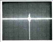
Fig. 8 Single-pulse test.

Fig. 9 Two-tone phase test signal (200 Hz and 2 kHz) with Digital Time Lens
off.
Figure 4 is a graph of distortion versus frequency for maximum recorded levels as well as for levels of-24 and -30 dB. At the-30 dB level, turning on the Digital Time Lens circuit resulted in higher distortion meter readings (not shown in the graphs). It was clear from 'scope observations, however, that this was not an increase in actual harmonic distortion, but rather the distortion meter's mistaking the added dither noise (see Sidebar) for new distortion components. The dither is about 82 dB below maximum recorded level, but that's only 52 dB below a-30 dB recorded signal. So, relative to such a lower level signal, the noise represents a level that is 0.25% of the signal level. And, sure enough, that's exactly the level of "distortion" that my distortion meter thought it was reading.
Output linearity was accurate down to-60 dB, within 1.0 dB. SMPTE-IM distortion measured 0.0025% at 0 dB (maximum) recorded level and 0.03% at-20 dB. The CCIR-IM (twin-tone) distortion was only 0.0037%; I could not detect any in-band distortion components during this measurement other than the basic, 1-kHz beat which constitutes the CCIR-IM component.
An analysis of signal-to-noise performance, both un weighted and weighted, is shown with the Digital Time Lens engaged in Figs. 5A and 5B. An analysis of unweighted S/N without the Digital Time Lens engaged is shown in Fig. 6. My tester would not plot an A-weighted S/N analysis for this condition, since the S/N was far over 100 dB. Reproduction of a 1-kHz, digitally generated signal (Fig. 7) was about as close to a true square wave as I have ever seen from a CD player that used digital filtering. The unit pulse test is shown in Fig. 8. Figure 9 shows a virtual absence of any phase error between a 200-Hz signal on one channel and a 2-kHz signal on the other. When there is zero phase shift between these two signals, the waveforms cross the zero axis in the same direction at the same time, and that is exactly what is happening in Fig. 9.
Figure 10 shows separation between channels with the Digital Time Lens deactivated. At midrange frequencies, separation was around 80 dB, decreasing to just under 60 dB at the extreme high frequencies. If you were to repeat my tests with the Digital Time Lens switched on, you would measure no more than about 15 dB of apparent separation! That's because when Carver increases L R content with this circuit he does so by adding out-of-phase right signal to the left channel and out-of-phase left signal to the right channel. Of course, a simple voltmeter can't tell that the opposite-channel content is out of phase, so you get a poor separation reading. In fact, when you listen to music with the Digital Time Lens on, separation and depth of imaging actually increase-which is one of the objects of this circuit.
Figure 11 (using the phase-check test signals used in Fig. 10) is an interesting 'scope photo in that it shows exactly what I have just described: The left signal with some right mixed into it and the right signal with some left mixed in.
Again, the waveforms appear to have a fair amount of crosstalk and, hence, poor separation. But careful study of the photo shows, in fact, that the "high-frequency" ripple on the low-frequency waveform is exactly 180° out of phase with the high-frequency signal on the opposite channel, while the low-frequency ripple seen "modulating" the envelope of the high-frequency signal is also 180° out of phase with the low-frequency signal of the alternate channel.
The Carver CD Player was able to track all but the last and widest section of the opaque wedge on my special defects disc. That is, it was able to overlook dropouts as wide as 800 microns. No problems were encountered in tracking the simulated dust spots, the greatest diameter of which was also 800 microns. Neither were there any mutes or skips when the laser pickup traversed the area of the disc that bore simulated fingerprint smudges. So, while The Carver did not do quite as well as some recent players that handled all of the defects on this test disc, it is not likely to give you any tracking problems unless you really mishandle your discs and cover them with scratches too wide for the player to correct. The player's resistance to external shock is very good, too.
Use and Listening Tests
In recent months I have tended to favor the sound of CD players that employ digital filtering, and The Carver CD Player is in this category. It almost goes without saying that the sound quality produced by this player was superb -- without the Digital Time Lens. So, what did the Time Lens contribute? I look upon this circuit as an option, one that can and should be used with certain CDs which seem to lack the depth that I feel belongs in a musical performance. You might argue that the equalization afforded by the Time Lens (to provide what some have described as a warmer sound) could just as easily be accomplished by judicious use of bass and treble controls, but that is not true. Look at Fig. 2 and you will agree that no simple bass and treble controls can create this kind of a response curve. A graphic equalizer might, but not everyone has a graphic equalizer or the ability to set it to this empirically derived curve.
As for myself, I almost wish that Carver had chosen to separate the equalization function of the Digital Time Lens from the (L + R)/(L - R) ratio manipulation, since some of my discs seemed to profit from the latter effect but suffer from the change in overall response. I would hasten to add, however, that many of my earliest CDs benefited from both effects (and probably from the dither noise, too, though--like Carver--I can't swear that I could hear improvement from that particular addition).

Fig. 10--Separation vs frequency.

Fig. 11--Two-tone phase test signal with Digital Time Lens on.
The important thing about Carver's Digital Time Lens is that you have control over it. You can turn it off if you don't need it, and you can turn it on for those discs that seem to sound better with it. I don't think anyone can fault Carver for giving us this option, and in fact I commend him for the extensive research which must have gone into the development of his latest audio innovation.
Whatever else you do when you audition The Carver CD Player, be sure to listen carefully to the Digital Time Lens for several minutes before you turn it off. Try such a slow NB test several times; it takes a bit of concentration to really appreciate what's happening. If, after all that, you don't like the feature, just turn it off. But I suspect that many owners of this CD player will use it selectively, putting little coded marks on their CDs that indicate whether they should be played with the Time Lens or not. I find nothing wrong with such an arrangement.
In emphasizing the Digital Time Lens feature, I don't want to overlook the basic CD player itself. It has a well-executed design which fits in nicely with Carver's growing list of fine products, and it is priced at a level that should make it affordable to a great many people who are ready for a good CD player.
--Leonard Feldman
(Source: Audio magazine, March. 1985)
Also see:
Carver Digital Time Lens Technology and Compact Discs (ad, Oct. 1986)
Discrete Technology LSI Mk. II Compact Disc Player (Nov. 1986)
= = = =