
Manufacturer's Specifications
System Type: Two way; sealed-box woofer, electrostatic tweeter.
Drivers: 10-in. (25-cm) woofer; three electrostatic panel tweeters.
Crossover: 1 kHz.
Nominal Impedance: 4 ohms.
Frequency Response: 44 Hz to 20 kHz, ±3 dB.
Practical Power Range: 20 to 250 watts.
Dimensions: 17 1/2 in. W x 10 1/2 in. D x 37 1/2 in. H (44 cm x 27 cm x 95 cm).
Weight: 50 lbs. (23 kg).
Price: $350 each.
Company Address: Epicure Products, 25 Hale St., Newburyport, Mass. 01950.
The EPI Stat 450 combines a conventional 10-inch woofer with an electrostatic tweeter array to produce an affordable system with exotic technology. Many audiophiles believe that only electrostatic speakers offer the ultimate in transparency and definition, and insist on using the principle in full-range configurations despite the resulting high cost, large size, and compromised bass performance. The Stat 450 avoids these drawbacks by using electrostatic panels only above 1 kHz, a range which they handle easily.
The technology of electrostatic loudspeakers may seem exotic, but it is not new. Electrostatic loudspeakers were invented in the early 1920s, before the moving-coil type with which we are most familiar. The early 'stats were not commercially successful because the insulator and diaphragm materials then available were unable to cope with the high operating voltages required.
The modern electrostat era began with the Janszen tweeter array in 1954 and the Quad full-range system in 1955. Since then, well-received systems have been marketed by Pickering, KLH, Dayton Wright, Acoustat, Infinity, Sound-Lab, Stax, Martin-Logan, and many others. The three panels used in the Stat 450 have a strong resemblance in size and construction to those of the innovative Janszen speaker of 33 years ago.
I find electrostatic loudspeakers intriguing because the underlying physics implies a natural compatibility between this kind of force generator and the air next to it. Consider that in a conventional moving-coil loudspeaker, the interaction of magnetic fields produces a force on an electrical conductor (the voice-coil). The dense copper- or aluminum-wire conductor tends to have a small surface area, which prevents it from transferring this force efficiently to the surrounding air in order to radiate sound. The moving voice-coil is therefore attached to a diaphragm (cone) whose size allows a more effective coupling. Sometimes a further acoustical transformer (a horn) is used.
The direct sound-producing action of the electrostatic force generator is a sharp contrast to the magnetic/cone/ horn system. The electrostatic loudspeaker is essentially a capacitor, one of whose plates is free to move in response to a changing electric field. The audio signal, amplified to around 1,000 V, produces the changing field; a thin conductive plastic film is the movable plate. Unlike a voice-coil, this plate is a surface, so it naturally couples to the air next to it.
So much for ideal theory. The electrostatic loudspeaker has plenty of difficulties in the real world. Amplifiers de signed for moving-coil loudspeakers are not optimum for the high-voltage, capacitive-load demands of an electrostat.
Fortunately, a transformer can be used to step up the voltage (one is used in the Stat 450), and modern amplifiers are tolerant of the capacitive loading. A low-current, high-voltage polarizing supply is also needed. It is ironic that the inherently high operating voltage of tube-type amplifiers is stepped down with an output transformer and back up again with the transformer in the electrostatic loudspeaker.
Direct drive from a tube amplifier would be a natural for an electrostat, but such systems are not available today as off-the-shelf items.
The related problems of directivity and large size must also be addressed in the design of electrostatic loudspeakers. The large radiating surface of an electrostat is dictated by practical electrode spacing and acoustic output requirements. If all portions of this surface move in the same direction, radiation will be directional when acoustic wave lengths are small compared to the size of the surface. Some electrostats combat this tendency with individual arrayed panels, curved construction, narrow vertical panels, or, in the case of the Quad ESL 63, a simulated point source.
Acoustic radiation from the rear of the panel is also a problem for electrostats, just as it is for moving-coil speakers. When wavelengths are long (low frequencies) compared to the size of the panel, front-to-back cancellation occurs. Even a large enclosure for the rear of the electrostat can produce an unacceptable air-spring stiffness. The most common solution is to do without an enclosure, letting the speakers be large in area but thin, so the panel acts as its own baffle. This technique has a secondary benefit: High frequencies radiated from the rear tend to be dispersed as they are reflected back into the listening area.
The Stat 450 has its own ways of maximizing the benefits of electrostats and minimizing the deficiencies. Polarizing voltage is obtained from a small d.c.-to-d.c. converter, located inside each cabinet and powered by a wall-plug transformer. The power requirement is very small, and no power switch is provided. The same circuit board, inside the cabinet, also carries the crossover and audio step-up transformer. This transformer is of modest size because it only handles signals above 1 kHz.
No attempt to control the front radiation pattern is evident in the Stat 450, other than an angling of the three vertically stacked electrostatic panels slightly upward toward the listener. Rear radiation from the three electrostatic panels is absorbed in a partitioned--off section within the cabinet, accounting for about 60% of the total internal volume.
The woofer portion is a conventional sealed-box type using a 10-inch driver with a special cone construction said to possess nearly ideal damping and stiffness properties.
The same closed-cell foam material which forms the half-roll surround at the cone's outer edge continues all the way to the cone's apex. On the cone proper, a clear, stiff, plastic material is laminated to this foam, producing a composite with the desired properties.
The tall and fairly light cabinet is finished in walnut-grain vinyl and has a detachable brown-cloth grille. Amplifier connection is made to spring-clip connectors in a recessed panel on the rear of the cabinet. While easy to use for zip-cord up to about AWG 12, these connectors will not directly accept the heavier gauge audiophile cables. The wall-plug polarizing-supply transformer has its own mini power connector on the same plate. A high-frequency level control and nameplate reside near the top of the attractively finished front panel. I suspect that this loudspeaker system will frequently be used without the grille attached, in order to show off the front panel's exotic look.
Measurements

Fig. 1-Magnitude of impedance.

Fig. 2 Complex impedance.

Fig. 3-One-meter on-axis frequency response, with 1.0 watt input into 4 ohms
(2 V).

Fig. 4-One-meter on-axis phase response.

Fig. 5 One-meter on-axis time response. Arrival at 4.3 mS is rear tweeter
radiation reflected off back of cabinet and passing through tweeter panel.

Fig. 6-Three-meter room response.

Fig. 7-Horizontal off-axis frequency response, front to rear.
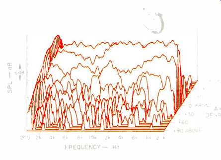
Fig. 8-Vertical off-axis frequency response, from below, up front, to directly
above speaker.

Fig. 9-Harmonic distortion products for the tone E1 (41.2 Hz).

Fig. 10-Harmonic distortion products for the tone A2 (110 Hz).

Fig. 11-Harmonic distortion products for the tone A4 (440 Hz).

Fig. 12-IM distortion on 440 Hz (A4) produced by 41.2 Hz (E1) when mixed in
one-to-one proportion.

Fig. 13--Power linearity at 10 and 100 watts. Reference is response at 1 watt.
This system's nominal impedance rating of 4 ohms is an appropriate one, even though the capacitive load of the tweeter brings it below this value at 20 kHz, as shown in Fig. 1. As can be seen in the complex impedance plot of Fig. 2, the upper frequencies lie primarily in the lower or capacitive half of the plot. The expected woofer and crossover resonances produce high impedance peaks with both capacitive and inductive phase angles. The sharp impedance peak at 65 Hz is due to the woofer's primary resonance. Its high magnitude is merely an indication of low mechanical loss in this system, which relies primarily on amplifier damping to control resonance. Other frequencies are harder to drive because they have a high positive or negative phase angle combined with a low impedance magnitude. however, even these more stressful points should be well within the capabilities of modern amplifiers.
Figure 3 shows the 1-meter, on-axis, anechoic frequency response. Audio's anechoic plots are made 1 meter out from the geometric center of the front panel, for consistency.
The low-frequency portion of Fig. 3 shows a bump in the bass response around 70 Hz and a 16-dB/octave cutoff below 50 Hz.
Figure 4 shows the 1-meter on-axis system phase response. The positive phase shift at extremely low frequencies (not shown) followed by a negative shift through the crossover range is a usual trend in a two-way system. The Stat 450 dives past-180° a little faster than usual and levels out at- 270° rather than continuing downward. A plot like this looks bad by amplifier standards, but if it is smooth and gradual, I believe it is not a problem to the ear.
Time response of the Stat 450 under the same 1-meter conditions is shown in Fig. 5. Although the primary sound arrival from the tweeter is very compact in time, it is followed by another arrival 1.3 mS later. This is the tweeter's rear radiation reflecting off the inside rear of the cabinet and passing out through the electrostatic panels. Neither the fiberglass in the compartment nor the panels themselves prevent this. This sound combines with the primary radiation to produce the regular peaks and dips in the response at frequencies above 1.5 kHz.
The 3-meter on-axis room response, shown in Fig. 6, includes room reflections that occur within 10 mS at a typical listening position. The relatively smooth portion be low 1 kHz is a tribute to the lack of floor-bounce interference from the low-mounted woofer. Higher mounting would cause the signal reflected off the floor to travel a significantly longer path to the listener than the direct sound, and the result would be cancellation at frequencies as low as 300 Hz. Low mounting forces the first cancellation notch to be much higher, and it allows the signal hitting the floor to possibly just be absorbed by a carpet instead of reflecting.
The upper range is affected by a side-wall reflection up to about 4 kHz. Above that frequency, the tweeter becomes sufficiently directional to eliminate this interference.
Figure 6 also shows the 3-meter room response measured 30° off-axis. While the plot is again relatively free of early reflection problems, interference notches and a general roll-off of the upper range are seen.
Horizontal directivity is seen in the "three-dimensional" plot of Fig. 7, showing frequency response from 200 Hz to 20 kHz measured at 6° intervals from front to back. Listening even 6° off-axis causes a noticeable loss in the upper octave. At 12° or more, the upper octave is just not there.
Vertical directivity is shown the same way in Fig. 8. Thirty one plots are made from directly below the speaker, up the front, to directly over the speaker. Again, high-frequency radiation is confined to a narrow angle.
Figures 9, 10, and 11 show the harmonics of tones at 41.2, 110, and 440 Hz (E1, A2, and A4) produced by the Stat 450 at applied power from 0.1 to 100 watts. The 41.2-Hz tone is below system resonance and may be considered at the edge of the effective range of the Stat 450. At high power, suspension or magnetic nonlinearities limit both ends of the cone travel, as indicated by the high third-harmonic content. The low percentages of upper harmonics indicate that this action is gentle and controlled. The higher frequencies, 110 and 440 Hz, have respectably low percentages of predominantly low-order harmonics, even at high power input. In sum, this is respectable linearity for a 10-inch woofer system.
Woofer linearity can also be evaluated by looking at Fig. 12, which modulation 440 Hz (A4) by 41.2 Hz (E1).
This is essentially a test of linearity at 41.2 Hz. As we might expect, the 440-Hz tone gets somewhat squashed when the 41.2-Hz tone strokes the cone to its limits. Ten-percent modulation of the 440-Hz tone occurs at 20 watts of combined input, and is audible, but at a high output level.
Power linearity, shown in Fig. 13, is a wide-band test for system power-handling and distortion. Frequency response measured at 1 watt is the reference. The response at 10 and 100 watts should be the same, but 10 and 20 dB higher. For clarity, only the differences in response (which ideally should be straight lines shifted up) are shown in Fig. 13.
Since the receiving analyzer tracks the swept tone sent out, distortion products are ignored. The Stat 450 does well at 10 watts input but shows some compression throughout the audio range at 100 watts. I would say this is reasonable performance considering the fact that the speaker's high sensitivity makes 10 watts quite loud.
Use and Listening Tests
The well-written instruction sheet that comes with the Stat 450 states that its high-frequency radiation is "rather directional." I agree with this statement because, at high frequencies, and particularly vertically, these are the most direction al speakers I have yet tested. Most of my initial setup efforts dealt with this characteristic, and eventually I achieved a reasonably successful setup.
I started by placing the Stat 450s out from the wall and angled inward toward the listening position, as recommended by EPI. Even with the high-frequency level control turned down, there was a tizzy top-end which prevented me from accepting an imaginary sound stage between and behind the speakers. In addition, image locations, for a centered listener, shifted with the slightest head movement.
Loudspeaker directivity can often be used to enhance the sense of a realistic sound stage over a larger listening area by rotating the cabinets even farther inward than one would usually expect. With this slightly "cross-eyed" orientation, a listener physically close to one speaker is more on the axis of the opposite speaker. This setup operates somewhat like an automatic balance control in that a channel level difference re-centers the sonic images. Applying this idea to the Stat 450s helped but was not the final answer. The high-frequency energy from the farther speaker would hit the listener, while the high frequencies from the near speaker would miss the listening position. Mid- and low frequencies were little affected by the angles used. The result was unstable image locations.
I even tried an extreme angle in which the speakers ended up looking more at each other than at the listener, and about 3 feet out from the wall. Like magic, the sound stage appeared; the highs were there, and image locations were stable! It turned out that the extreme angle projects each speaker's beam of highs across the room into the opposite wall, where it is reflected back to the listening position. To optimize the effect, I placed large, acoustically diffusing objects along the two side walls at which the speakers were now aimed. An audio equipment cabinet or a partially filled bookcase works very well as a diffuser. What I perceived was an unexpected sense of "air" and a widening of the sound stage on complex sounds like applause.
With the speakers 3 feet out from the wall behind them, the bass was a bit thin. After experimenting with positions closer to the wall, I ended up with the back of the cabinet about 1 foot out. Bass was now in balance but not as extended as I would like. Upper bass was smooth, but the midrange exhibited some unevenness. There was no sense of coloration, just a bit of aggressiveness in one octave and a bit of suppression in the next. Highs were extended and airy, as long as the listener remained seated.
The open sound and image locations of these speakers were more consistent with side-to-side changes in listener position than that usually found in front-directed setups.
Depth of sound stage was a bit shallow at times, and one's ability to differentiate between large hall ambience, club sound, and dry recordings was less than with some other good speakers. Selections from Sheffield's Drum Record were reproduced without a sense of strain or compression at quite respectable levels with the speakers driven by a 250-watt amplifier. Focus and sharpness of attack on this percussive material were somewhat lacking, however. Many listeners gave strong praise to the sound from the Stat 450s in the final orientation.
For the would-be electrostatic loudspeaker enthusiast who has never been able to afford a pair, the EPI Stat 450s provide an entry-level opportunity to indulge in this old but still-exotic technology.
-David L. Clark
(adapted from Audio magazine, Feb. 1987)
Also see:
EPI 601 Speaker Systems (Jan. 1973)
Epicure Model EPI-100 Speaker System (May 1970)
= = = =