by Victor Broclner [Vice President Engineering, H. H. Scott, Inc. ]
Horn loudspeakers are used whenever high efficiency is required and when special control is desired over directional characteristics. In a well-designed horn speaker, distortion is lower than in a direct radiator, at least towards the low-frequency limit of its range. Bass horns are capable of producing high sound pressure levels with a small cone excursion; because of this, both nonlinear and Doppler distortions are lower than in direct-radiator woofers. Direct-radiator speakers become more directional as the frequency increases. Horns can be designed to provide good directional patterns up to the highest frequencies.
The theory of horn speakers to be found in textbooks is highly mathematical, difficult to understand, and very abstract. It does not provide a good intuitive understanding of horn speaker operation. Popular books, on the other hand, tend to present ostensibly simple explanations that are really not much more comprehensive. What is mean by saying that a horn is an impedance transformer? How does a horn "load" a driver unit? When a speaker is loaded by a horn, doesn't the increased load reduce the diaphragm excursion? If so, why does the acoustic output increase? This article is an attempt to explain horn speaker operation in terms that provide both an intuitive and a quantitative understanding, without using advanced mathematics. It will be assumed that the reader has some acquaintance with electrical analog circuits for mechanical and acoustical systems, and with concepts such as radiation impedance, motional impedance, mechanical compliance, and the like. It is freely confessed that, in the course of the development, some shameless simplifications will be made. The following is certainly not represented to be a design manual.
[Leo L. Beranek Acoustics 1954 P. 124 Table 5.1 ]
Direct radiator speakers have low efficiency because there is a bad mismatch between the impedance of the mechanical power source and the air into which it radiates sound, except at resonance, where electrical mismatching reduces the output.
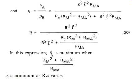
Fig. 1 is an analog circuit for a direct-radiator speaker in its middle frequency range in which losses are neglected. In this circuit, the acoustic output is the power produced in the radiation resistance RMA by the velocity v:
PA = V^2 RMA (1)
Over the flat section of the frequency response curve shown in Fig. 2, the motion of the cone per unit of applied force is determined almost entirely by the mass of the moving system:
V= F / 2 pi fm (2)
where v = cone velocity in meters per second
F = force applied by the voice coil, in Newtons
f = frequency, in Hertz
m = mass of the moving system (coil and cone) in kilograms
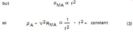
Equation (2) shows that cone velocity is inversely proportional to frequency. Figure 2 depicts this variation. The dashed curve shows how v2 varies with frequency. The radiation resistance, RMA, is a function of the square of the frequency, as shown by the dot-dash line. Now, referring to equation (1), the acoustic power output is derived as follows:
(3)
This is seen in the power-frequency response curve of Fig. 2.
Suppose the voice coil mass plus cone and air load mass equals .03 kg. At 400 Hertz, where the frequency response is flat, the reactance of the mass is
Xm = 2 pi fm = 6.28 X 400 X .03 = 75 mechanical mks ohms
This is the effective impedance of the generator. The load,
RMA = 1.57 w^2 a4 ρ o/c*
where ω 2 pi f
a = radius of piston in meters
o = air density in kg/m^3
c = velocity of sound in m/sec.
Simplifying: RMA = .0132 d^4 f^ 2 where d = piston diameter in meters (5)
for a 10-inch cone, d = .24 meter approximately
At f = 400 Hertz RMA = .0132 x (.25)^4 x 400^2 = 8.25 mechanical mks ohms
So a 75-ohm generator feeds an 8.25-ohm load. This indicates the degree of mismatch in a typical case of a direct radiator speaker.
Matching can be improved by reducing the generator impedance or increasing the load impedance. The reactive generator impedance can be cancelled out by resonating its mass with a compliance. This is what happens at the resonance frequency of a direct radiator. At and near this frequency, the impedance match is good, and the mechano-acoustic efficiency is high. However, the low mechanical impedance that occurs at resonance is reflected into the electrical circuit as a high impedance, as a result of which the speaker cannot absorb much electrical power from the amplifier, that is, if the speaker is well damped. If not, there is bump in the response curve at resonance. This is not the kind of efficiency we want.
The reactive generator impedance can also be reduced by reducing the mass, m. This is done in tweeters by using small, aluminum voice coils and very light cones. In wide-range speakers or woofers, there is a limitation to mass reduction because the cone must be sufficiently strong so as not to buckle or break up into modes. Another problem is that reducing the mass raises the frequency of resonance, below which the frequency response falls rapidly. It also reduces the Q of the moving system, since
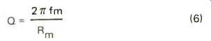
(6)
where Rm is the damping resistance. An over-damped speaker has a frequency response that falls off as the frequency de creases. All of these factors are undesirable consequences of excessive lowering of mass.
This leaves the factor RMA--the radiation resistance. Since RMA increases proportionally to the area of the speaker, it is a simple matter to make it larger. But increasing the size of the cone raises its mass; rather rapidly, in fact, because the thickness has to be increased as well to maintain adequate stiffness. This works to counteract the increased efficiency obtained by the larger cone. Also, as examination of the frequency response curve of Fig. 2 discloses, the point at which the high-frequency response falls off is lower the greater the cone diameter. For a theoretically perfect piston, the drop in response begins at f = 8600/d where d is the piston diameter in inches. Thus, a 10-inch piston begins to drop in response at 860 Hertz, a 15-inch diameter results in a 573-Hertz transition point, and so on---- downwards.
[It is not correct to couple steps together like this because there Is an Impedance mismatch, but in this case the end justifies the means. ]
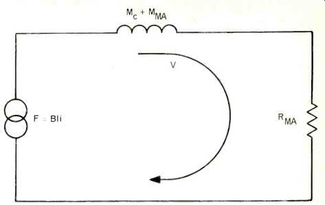
Fig. 1--Mechanical analog circuit of direct radiator loudspeaker with a constant
current drive. Frictional losses are assumed as zero. F = force exerted by
voice coil in Newtons; I = length of voice coil conductor in meters; i = current
in voice coil in amperes; me = mass of voice coil and cone in kilograms; mMA
= equivalent mass of air load in kilograms, and RMA = radiation resistance
in mks mechanical ohms.

Fig. 2--Calculated performance of piston as direct radiator.
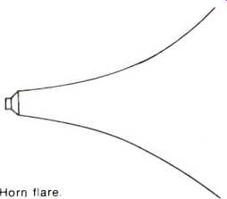
Fig. 3--Horn flare.
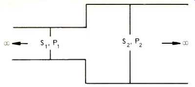
Fig. 4--Acoustic power transmission through stepped pipe. Si. S2 = cross-sectional
areas; Pi, P2 = power transmitted, and rP = P2/P1.
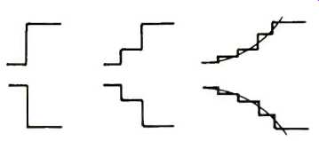
Fig. 5--Limit of successively larger numbers of steps of expansion of a pipe
for identical initial and final diameters.
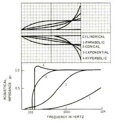
Fig. 6--Expansion rates of various types of horns. S = area at distance X
from throat; Sr = throat area. Parabolic: S= ST (1 + X/X0); Conical: S=
Sr(1 + X/X0)2; Exponential: S = SreMx; Bessel: S = Sr (X + Xo)M; Catenoidal:
S = Sr (eMx + e-Mx); Hyperbolic: S = Sr(cos H X/Xo + T sin X/Xo) 2. T is
less than 1.
Increasing Radiation Resistance
If we could somehow manage to persuade a cone to produce plane waves, the radiation resistance would be 407 mechanical mks ohms per square meter of radiating area. A 10-inch cone, with an area of .05 square meter, would then work into 407 x .05 or 24 ohms which is certainly more favorable than the 8.25 ohms calculated in the example given above. We know that sound that is not too high in frequency is propagated as a plane wave along an infinitely long pipe. We could presumably get better efficiency by coupling the speaker to such a pipe. However, we might not care to wait around until the sound emerged from the pipe! What about a very long, but not infinite, pipe? The load on the speaker would be favorable, but now, at the mouth of the pipe we face much the same situation as we had with the speaker radiating directly.
The only way around this problem is somehow to attain a larger area at the point of transfer of sound from the pipe to the surrounding air. Fig. 3 shows a way of doing this. The expanding passage employed is called a horn.
To determine exactly how a horn works even with simplifying assumptions, requires abstruse mathematical treatment.
However, there is a simplified approach which, although anything but rigorous, can convey a rather good idea of what goes on in a horn. Let us consider the propagation of a plane sound wave through a small pipe that feeds a larger one as shown in Fig. 4. Assume that both pipes are infinite in length. The acoustic resistance of the small pipe is 407 S1 mechanical mks ohms, S, being its cross-sectional area in square meters.
The large pipe has an acoustic resistance of 407 S2. The resistances are not matched at the junction, so some reflection takes place, and not all of the power is transmitted from one pipe to the other.
The ratio of power transmitted is where
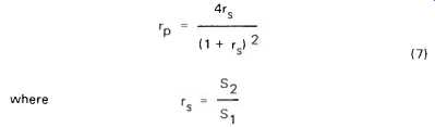
(7)
It is interesting to note that S2/S1 can be appreciably larger than 1.0 without a great deal of power loss. For example, a 1.5 to 1.0 ratio results in 96% transmission of the incident power. This suggests that it might be feasible to transfer power without excessive losses to a larger area by means of successive small steps of expansion,* as in Fig. 5. Calculations on increasing numbers of steps of expansion for a given ratio of S2 to S1 reveals a definite trend that can be seen in the following:
Table 1
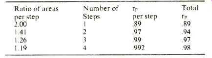
In all four cases, the ratio of output area to input area is 2.00 and it is evident that increasing the number of steps raises the efficiency of transmission. The trend appears to indicate that the limit of a continuous curve is 100% transmission. Now, if the far end of the pipe can be made large enough so that it produces plane waves, just as plane waves would be radiated by a large piston, the finite pipe behaves like an infinite pipe.
There is no problem at the far end, power is transmitted 100% along the pipe (except for frictional losses) and the desired increased load is obtained on the diaphragm of the driving speaker. The device we have "invented" is a horn; the end near the speaker is called the throat and the far end the mouth.
Horns: Infinite and Finite
The shape of a horn is expressed by a mathematical formula indicating the ratio of the horn cross-sectional area at a given distance, x, from the horn throat, to the area of the horn mouth. The most widely used horn is exponential:
S2/S1 =e^mx (8)
where S2 = mouth area
S1 = throat area
m = flare constant
x = distance from throat
In this type of horn, each increment of distance results in a constant ratio of areas:
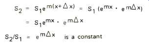
This is the type of horn we developed as a limit of the stepped pipe as the number of steps per unit distance increased indefinitely. Other useful horn shapes are Bessel, catenoidal, conical, hyperbolic, and parabolic. These are all shown in Fig. 6. The conical horn is the oldest form of artificial horn, seen in megaphones. The oldest natural form is approximately paraboloidal, consisting of a pair of cupped hands held before the mouth. Paraboloidal horns are used, in segments of different flare rates, to approximate horns of other expansion laws, in low-frequency horns. Many folded bass horns, which are usually made of wood, use a succession of short sections with a pair of parallel sides, the other pair expanding linearly. The area of such a horn section follows a parabolic law of expansion.
The hyperbolic and Bessel horns are families of horns, the exact curve depending on the values of certain parameters. The hyperbolic horn becomes exponential when T = 1, and catenoidal when T = 0. The Bessel horn becomes conical when m = 1.
Fig. 7 shows a comparison between the radiation resistance of a loudspeaker radiating directly into the air and the same unit working into an exponential horn. There is a large increase in radiation resistance at frequencies below the knee of the curve for the direct radiator, and none at all for high frequencies. The lack of improvement at the top end is not surprising when one realizes that a direct radiator produces virtually plane waves at high frequencies. These can be visualized as emerging as a beam from the speaker without being affected by the horn walls.
All of the curves go to very low values of radiation resistance as the frequency is decreased below a certain point. In an exponential horn, for example, the radiation resistance becomes zero when:
fc = me/4 pi (9)
where fc = cut-off frequency
c = speed of sound
m = flaring constant.
The radiation resistance does not actually go down to zero, but retains a small finite value, not given by the usual horn formula because of the simplifying assumptions adopted in its derivation. At __/2 fc, R_MA is 1 __/2 of its ultimate value. A horn driven by a piston whose velocity is independent of frequency has a sound pressure level that is down 3 dB at this frequency.
A convenient, if approximate concept, is that below the cut-off frequency the air in the horn does not propagate as a travelling wave but simply oscillates in the horn so that the pressures in all planes at right angles to the horn axis are in phase. Under these conditions the air acts like a moving mass.
As a matter of fact, the air in the horn does not move exactly in phase with the driving pressure even in its working range; in other words, the acoustic impedance looking into the horn throat is not a pure resistance. The formula for the throat reactance is:

(10)
in which, be it noted, the frequency term is in the denominator. The reactance is positive, which leads one to conceive of it as a mass reactance, but it decreases as the frequency increases, as does a capacitance. Actually, the reactance is that of a negative capacitance. It acts to decrease the velocity for a given applied force, reducing acoustic output.
There is another limitation at low-frequencies as well, which is not shown by the curves of radiation resistance (Fig. 6) because these are based on horns of infinite length. It may be recalled that in developing the horn via the stepped pipe, it was stated that the mouth size had to be great enough for the assumption that it radiated plane waves.
Adequate "mouth loading" is generally considered to be provided when the circumference of the horn is equal to a wavelength, or pi d = lambda . This is somewhat easier to deal with in terms of frequency: f = c/lambda where c is the speed of sound.
The resulting expression is:
d = c/pi f
For d in inches, d = 4300/f.
This is exactly one octave below the frequency at which the radiation resistance curve of a direct radiator has its knee. (See Fig. 2)
The formula provides some discouraging information. For example, a horn that performs well down to 43 Hertz has to be over 8 feet in diameter! Fortunately one can live with considerably less than perfect mouth loading. Also, the use of room walls and floor as reflectors increases the effective area.
Bass horns designed to fit into the corner of a room work very well with equivalent mouth diameters not much greater than 2 feet.
If we now consider the frequency response of the simple horn speaker in the mid-frequency range we find that we do not obtain a flat frequency response.
At 400 Hertz we found the mass reactance to be 75 mks mechanical ohms; by means of the horn the radiation resistance load was increased to 24 ohms, but this still leaves the mass largely in control of the velocity (See Fig. 1). Meanwhile, the radiation resistance has become independent of the frequency (See Fig. 7). Since the velocity v still decreases with increasing frequency and RMA remains constant, the formula PA = v^2 RMA tells us that the response falls toward the high-frequency end. If RMA is frequency-independent, v must be constant as well. This condition can be approached if RMA is much greater than the mass reactance.
RMA can be increased still more if the speaker is coupled to the horn by means of a stepped-down pipe as in Fig. 8. Now the speaker looks into a mechanical resistance
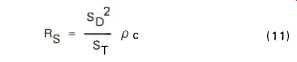
(11)
where So = the diaphragm area
and ST = the throat area
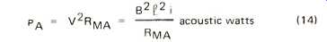
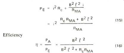
If SD/ST = 4; Rs= 4 X 24 X 96 mks mechanical ohms which approaches the condition we want of resistance-determined cone velocity. With true resistance control, the response is flat in the mid-frequency region. The variation with frequency of the response determining parameters as well as the response curve itself, are shown in Fig. 9a, and the analog circuit in 9b.
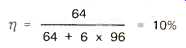
As the frequency increases, the mass reactance begins to predominate in determining the velocity, which decreases. The power output drops at a rate of 6 dB per octave. Eventually, the compliance of the front air chamber Cc begins to act like a shunt across the radiation resistance RMA, and response falls rapidly. If the low-pass filter formed by ms and C is proportioned so that it is suitably mis-matched, the response in the region immediately below A can be elevated as shown by the dot-dash line with response falling above this point at a rate of 12 dB per octave. See Fig. 9c. At low frequencies the response falls because X_MA, as has been pointed out, is a negative capacitance, whose reactance increases, decreasing the diaphragm velocity. However, if the speaker resonance is placed near the horn cut-off frequency, the speaker compliance can be made to cancel out the negative compliance of the horn, removing this restriction and increasing the bass response. In high-compliance woofers, the required lower value of compliance can be obtained by enclosing the rear of the speaker in a very tight box.

Fig. 7--Radiation resistance of exponential horn versus piston in infinite
baffle.
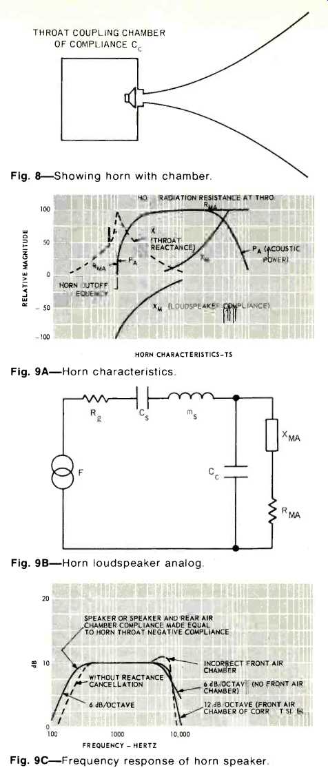
Fig. 8--Showing horn with chamber.
Fig. 9A--Horn characteristics.
Fig. 9B--Horn loudspeaker analog.
Fig. 9C--Frequency response of horn speaker.
Efficiency
We have found that adding a horn to speaker unit improves the impedance matching and increases the power output for a given driving force of the voice coil. What about the efficiency? Let us simplify the problem by considering the frequency range over which the cone motion is resistance-controlled, and neglect losses due to friction. The efficiency under these idealized conditions is called the initial efficiency.
The force exerted by the voice coil:
F = Bli
where F is in Newtons
B = magnetic flux density in Webers/square meter.
l = length of voice coil conductor in meters
The cone velocity
V = F/R_MA (13)
where v is in meters/second R_MA = radiation resistance in mks mechanical ohms.
Substituting from (12) to (13),

(12)
Using the formula for acoustic power:
(14)
The input power consists of the electrical power dissipated in the voice coil, plus that corresponding to the acoustic power.
(15), (16)
For a 12-inch speaker with B^2 I^2 = 64 and R = 6 ohms, and R_MA = 96 ohms as in the horn previously analyzed:
This is not a startlingly high efficiency, but it is a great deal better than the typical 1% or lower efficiency of a typical high compliance woofer.
How can efficiency be increased? Equation (16) tells us:
Increase the flux density B, the length of voice coil conductor, reduce the voice coil resistance Rc, or reduce the radiation resistance RMA. The first three items are somewhat interdependent. If 1 is increased, Rc is increased, opposing the increased efficiency, unless the wire diameter is increased. If this is done, the air gap must be made greater to accommodate the thicker voice coil, reducing B. Also, the moving mass increases, and its greater reactance opposes the condition of resistance control at a lower frequency, reducing the high frequency response. It can be seen that a great deal of juggling must be done to obtain the desired performance.
Now for the last factor: RMA. To increase efficiency, this must be decreased. But the whole point of horn loading was to increase RMA. There seems to be a contradiction here. It is the result of the simplifying assumptions. For the direct radiator, we assumed mass control. For this condition, RIA should be as great as possible. The horn efficiency equation was based on resistance control. Here, RMA should be as small as possible. But if RMA is made small compared to the mass reactance, the condition of resistance control no longer applies. One would expect an optimum point somewhere in between.
If an intermediate condition is assumed between mass control and resistance control, both elements must be taken into account in the expression for the velocity which now becomes
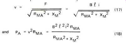
(17), (18)
Now the input power is the sum of the output power and the power dissipated in the voice coil
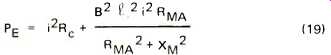
(19)
and
(20)
Fig. 10--Analog circuit of horn loudspeaker operated from constant-voltage
source. The horn throat reactance is assumed to be cancelled out by the speaker
compliance.
This occurs when RMA = XM. Then the maximum possible value of efficiency.
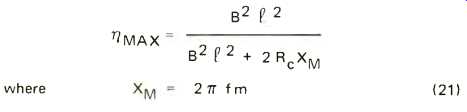
(21)
Since XM varies with frequency we can select f to produce a maximum anywhere we please as long as XM = RMA at some point on the flat part of the curve of RMA vs. f.
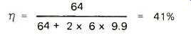
Assume that this point is 50 Hz. Then for a .03 Kg moving system XM = 2 pi X 50 X .03 = 9.9 mks mechanical ohms. If this is matched by making R_MA = 9.9 ohms also, then for the speaker previously considered as a direct radiator:
For the same system at 500 Hz, XM = 2 pi x 500 x .03 = 99 mks mechanical ohms. However, RMA is fixed at 9.9 ohms.
Now
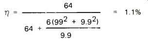
The high efficiency at 50 Hz has been obtained at the expense of a response that drops rapidly as frequency increases. This is an illustration of the concept of gain-bandwidth product. As the required bandwidth increases the efficiency goes down.
There is still another method of obtaining high efficiency that can be derived from equation (21). This is to reduce XM by decreasing the moving mass. One way to accomplish this is to use a smaller cone. This is feasible because high values of RMA can be obtained by means of the horn rather than through the use of a large radiating area.
Constant-Voltage Operation
In all the previous calculations it was assumed that the loudspeaker was operated from a constant-current source. This assumption brings about a considerable simplification in the formulas and provides a valid expression for efficiency. However, it does not provide a correct expression for the frequency response of the loudspeaker as actually used: From an essentially constant-voltage source. The reason is that the electric impedance varies with frequency. Because of this, the input power also varies with frequency.
The mechanical analog circuit of the loudspeaker must be modified from that of Fig. 1, when a constant-voltage amplifier is used. The revised circuit is shown in Fig. 10.
M is the mass of the moving system and RMA the radiation resistance in mechanical units as before. The series resistance represents the effect of the voice coil resistance. Its value is derived as follows: Think of a loudspeaker whose voice coil motion is blocked by some means. If v = 0, there must be an open circuit in the loop shown in the figure. This corresponds to the manner in which we would measure the open-circuit voltage in an electric circuit. On the electrical side, there is no counter-e.m.f. generated since there is no motion of the voice coil. The only current-determining element in the circuit is Rc, the voice coil resistance. So i = E/Rc where E is the amplifier output voltage. Substituting in the expression for:

Now consider what happens if the loudspeaker is operated into a vacuum and there is no friction. Nothing opposes the motion of the cone. This corresponds to a short-circuit across A-B. In the mechanical circuit
---p26
The velocity must be just enough to generate a counter-emf that equals the amplifier voltage. Then Blu = E and substituting from the previous expression
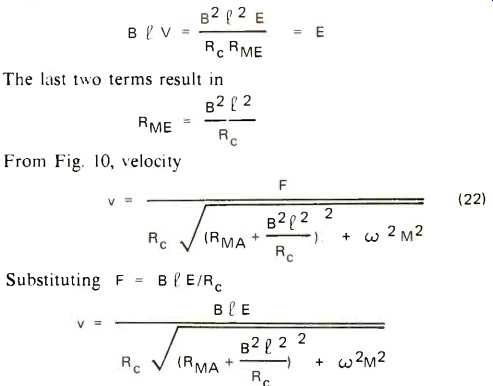
(22)
---p26
We can now find a means of calculating the frequency response of the loudspeaker. The relative response is plotted as sound pressure vs. frequency. Since sound pressure is proportional to the square root of the power, it is convenient to think in terms of the ratio
which corresponds to sound pressure per volt applied to the loudspeaker terminals. From the relation
PA = V^2R_MA we write
(23)
Since omega-m increases with frequency, the response begins to drop above the frequency where omega-m becomes comparable in magnitude to:
Using the constants for the horn speaker whose efficiency was previously derived for 50 Hz and 500 Hz.

This is a drop in response of 2.5 dB. The previous calculation for constant current operation showed a drop of over 16 dB. Substantially better frequency response can be obtained with a constant-voltage source because the electric impedance of the speaker decreases at high frequencies and permits more current to flow.
Midrange and High-Frequency Horn Speakers
To this point we have considered only the case where a horn is added to a direct-radiator loudspeaker. Where both extreme low-frequency range and power capability are not needed, horn loudspeakers can be made more efficient by using small, light, rigid diaphragms. Small diaphragms reduce the value of R_MA, increasing the efficiency; the moving mass is also lowered, extending the high-frequency response. The smaller driver unit is capable of handling large amounts of power without excessive diaphragm excursion because of the greater load into which it works. The expression for the power output of a loudspeaker indicates that, for a given amount of acoustic power at a given frequency, the required rms velocity is inversely proportional to the square root of the mechanical radiation resistance imposed by the acoustic load. The required excursion is proportional to the velocity. A 10-inch come as a direct radiator, with an area of .05 m2, works into 8.25 ohms at 50 Hertz. Horn-loaded to 96 ohms, its excursion for a given acoustic output would be
√ [8.25/96]
or about 0.3 times as great as before. Alternatively, the cone size could be reduced and the radiation load maintained by decreasing the area of the horn throat, which would result in a longer horn.
The excursion varies inversely as the square of the frequency; consequently this requirement becomes rather unimportant except in the bass range. If a direct radiator requires a 3/8-inch peak excursion at 50 Hz, this would be decreased to perhaps 1/8-inch by horn loading. At 500 Hz the excursion would be only 0.0013". Since it is easy to obtain appreciably greater excursions than this in small-diaphragm drivers, mid-range speakers for horn loading can be made quite small. A 3-inch diameter diaphragm is typical in such an application. Diaphragms of this type are frequently dome shaped and made of aluminum alloy or formed plastic. Consequently they are extremely light. Tweeters use even smaller diaphragms and lighter voice coils.
(To be continued)
(adapted from Audio magazine, Mar. 1971)
Also see:
Tractrix Horns--Improved Imaging and Phasing (Mar. 1991)
Loudspeaker Design--Hofmann's Iron Law (Mar. 1971)
= = = =