
MANUFACTURER'S SPECIFICATIONS
System Type: Vented, equalized system
Nominal Impedance: 8 ohms
Frequency Response: 32 to 18,000 Hz ±3 dB
Dimensions: Speaker, 14 in. x 22 in. x 7-3/4 in.; equalizer, 2-3/4 in. x 8 in. x 7 in.
Net Weight: Speaker, 27 lbs.; equalizer, 2 lbs., 10 oz.
Price: $450.00 per pair with equalizer.
Standing only 56-cm (22-in.) high by 36-cm (14-in.) wide and 18-cm (7-3/4-in.) deep, each speaker of this system promises to be that something which can be placed on any reasonable shelf, a true bookshelf speaker. When it comes to sound output, however, this small size is deceptive because the Interface: A is one of the newer breeds of loudspeaker designed for extended low-frequency response through optimizing system parameters rather than brute force methods.
The basis of this design is the fine work of the Australian researcher, A. N. Thiele, who is a leader in describing loudspeaker low-frequency response in the same terms as used in electrical network theory. This, in turn, has led to a much more straightforward method of design than had been previously used by loudspeaker designers.
In the case of the Interface: A, the designers chose to use a system response corresponding to that of a sixth-order Butterworth high-pass filter with a 3-dB frequency of 32 Hz.
Instead of using a vent to achieve this system response, Electro-Voice uses a passive radiator, which they prefer to have known as a "vent substitute." Whether we call it a drone cone, passive radiator, or vent substitute, the device, which replaces the equivalent of a 6.1-meter (20-ft.) long air vent, is a loudspeaker without a voice coil that is mass loaded by 400 grams to provide the equivalent volume of air.
In order to achieve the sixth-order alignment, auxiliary equalization is needed, which takes the form of a boost at about 36 Hz and is provided in a preamplifier accompanying the two speakers. This is not a just simple bass boost to give more low frequency kick, but is designed specifically as a complement to the acoustic response in order to achieve the desired result.
A 20-cm (8-inch) front-mounted woofer provides direct output for frequencies up to 1500 Hz, as well as driving the vent substitute. A front-mounted tweeter takes over for frequencies above 1500 Hz. In order to improve the total high frequency energy in a room without making the front response too hot, a rear-mounted tweeter carries frequencies above 8 kHz and augments the response of the front tweeter.
The enclosure is walnut finished, with a removable black grille. Loudspeaker connection is made to well-marked terminals on the rear. There is one possible point of user confusion present in the form of an additional set of connections directly below the two speaker terminals and called "tweeter protection." These are provided for an optional protection device for the tweeters, but a hasty hookup could result in improper connection, particularly for the "do-it-yourselfer" who relies more on touch than on the written instructions when the rear of the enclosure is against a wall and poorly lit.
The user who takes the time to read should have absolutely no problem with this system, however, because the clearly written set of instructions which accompanies the Interface: A covers virtually everything the user might need to know. The Interface: A is warranted against malfunction due to defects in workmanship and materials for a period of 5 years from the date of original purchase.
Technical Measurements
The electronic preamplifier is an essential element in the reproduction properties of the E-V Interface:A since it not only provides the proper bass equalization but also establishes the treble properties by means of three switchable high-frequency contours. Figure 1 is the measured frequency response of the preamplifier for each of the three control positions. The bass response is the same for all positions and corresponds to a 6-dB peak at 35 Hz with a rapid rolloff be low 25 Hz, which should keep the woofer out of trouble with subsonic signals such as those due to warped records.
The high frequency response varies from a 5-dB peak at 20 kHz for position 1, to an 8-dB drop for position 3.
The preamplifier can be safely switched on or off without causing a voltage surge in the output signal, which is important from the standpoint of speaker protection. There is however, a substantial signal that can pass through the preamplifier when its power is removed and cause a distorted reproduction. For that reason the preamplifier should be powered from a convenience outlet in the master system so that it turns on with the other components.
The measured magnitude of impedance is shown in Fig. 2 for frequencies from 20 Hz to 20 kHz. This system uses a passive radiator and technically has the characteristic impedance of a vented speaker with two bass resonance peaks.
The lower peak occurs at 18 Hz and is just below the lowest frequency on this plot. The higher peak is at 68 Hz. The largest peak is around 1.3 kHz and is associated with the high frequency drivers.
Figure 3 is the complex impedance plot corresponding to Fig. 2. The lowest impedance is resistive and is around 5 ohms at 180 Hz. The frequencies of maximum phase lag corresponding to the greatest stress on a power amplifier, are 80 Hz and 2 kHz. The low phase angle at 2 kHz indicates that most amplifiers should be capable of driving the Inter face: A to near clipping levels without breakup.

Fig. 1-Frequency response of preamplifier in E-V Interface: A system.
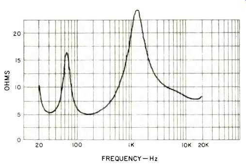
Fig. 2-Magnitude of impedance.

Fig. 3-Complex impedance.

Fig. 4-Anechoic, one-meter on-axis amplitude response with one-watt average
drive level.

Fig. 5-One-meter pressure phase response, corrected for time delay of woofer
and time delay of tweeter.

Fig. 6-One-meter anechoic response of rear tweeter.

Fig. 7-Three-meter room response.

Fig. 8-Horizontal polar-energy response.
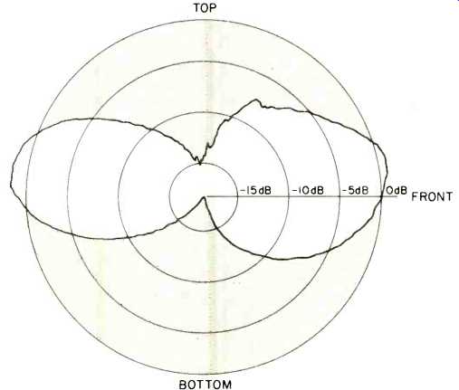
Fig. 9-Vertical polar energy response.
The anechoic one-meter on-axis pressure response with one-watt average drive is shown in Fig. 4 for the magnitude of sound pressure and in Fig. 5 for the phase. This response was measured with the preamplifier set to position 2. The response shows a tendency to roll off smoothly below 50 Hz with a trend toward a rounding off rather than a precipitous drop from a flat plateau. The magnitude of sound pressure extends quite uniformly through the important mid frequencies and has a slight overall downward tilt of about a dB per decade of frequency. The extreme top drops off above 13 kHz but still maintain a respectable level at 20 kHz.
The phase response, Fig. 5, shows a small non-minimum phase break at around 400 Hz and at the acoustic crossover at 2.8 kHz, with another break around 9 kHz. The phase plot is in two parts and is corrected for the acoustic positions at 1 kHz and 10 kHz. The acoustic position of the tweeter is 5.5 cm (2.2 inches) in front of the woofer. Both the woofer and tweeter are phased at zero degrees, which means that a positive voltage applied to the positive marked speaker terminals produces an in-phase pressure increase when the air path delay is subtracted from the measurement.
One surprise is that the rear-mounted tweeter is considerably "hotter" than the front-mounted tweeter for frequencies above 10 kHz. The one-meter response on the rear on the Interface:A is shown in Fig. 6 for the magnitude of sound pressure.
The near-field pressure response of the Interface:A, with the preamplifier equalization, shows a peak in response at around 38 Hz for the passive radiator and a characteristic dip at 30 Hz for the active driver.
The three-meter room response, corresponding to the tonal properties to be expected in an average listening situation, is shown in Fig. 7. The speaker is mounted one meter above the floor and the rear of the enclosure is 46 cm (18 in.) away from a back wall. Two responses are shown, separated 10 dB for clarity. The on-axis response is measured three meters directly in front of the enclosure and one meter above the floor. The other position has the same distance but is 30 degrees off-axis, corresponding to the response to be expected for a left-channel stereo position. Equalizer position 2 was used for this test. The effect of the rear-mounted tweeter is evident in the stereo position where the sound reflected off the wall carries the response to nearly 18 kHz. Except for a diffractive dip at around 2 kHz, the response is reasonably uniform throughout the useful frequency range.
A second set of three-meter measurements (not shown) was made for the condition where the rear of the speaker is only 10 cm (4 in.) from the wall. The effect of this is to reduce the extreme high frequencies and to introduce a mid frequency rise at around A4 or 440 Hz. I would recommend pulling the speaker away from any rear wall for smoother response.
Figures 8 and 9 are the horizontal and vertical polar energy response, respectively. The energy density of all frequencies from 20 Hz to 20 kHz is integrated for this measurement. Clearly the rear tweeter, which is handling half the frequency range from 10 kHz to 20 kHz, walks away with the energy honors. This gives a dipole-type response commonly found only in open-back electrostatic speakers.
For some reason not evident from physical inspection, there is a left-right di-symmetry of the horizontal dispersion.
This implies that the speakers should be rotated toward the listening area for a better balance in stereo reproduction.
Sound is launched slightly upward. The shape of the vertical response implies that the Interface:A should not be mounted near a ceiling or immediately below a hard reflecting surface.
Harmonic distortion is shown in Fig. 10 for the tones E1 or 41 Hz, A2 or 110 Hz, and A4 or 440 Hz. The distortion at A4 is low throughout the power range. The mid bass tone A2 begins to show stress above 20 watts, and the power handling drops significantly for the low bass tone of E1. These measurements were not made through the preamplifier, but were made with respect to the actual drive power on the speaker terminals. In view of the 6-dB pre-emphasis of the preamplifier at E1, and the fact that sonic distress occurs at levels above 40 watts (where we terminated the measurement), I do not recommend that this speaker be used to reproduce such demanding material as Bach's Toccata and Fugue at loud levels, as it would not be musically accurate and could lead to speaker damage if high-power amplifiers are used.
The intermodulation of A4 by E1, or 440 Hz by 41 Hz, mixed one-to-one, is quite low, as shown in Fig. 11. The IM starts at one-tenth percent at an average power of one tenth watt and climbs slowly to a low level of 6.36 percent at 100 watts. The nature of this distortion at its maximum level is mostly amplitude modulation with approximately a one degree peak-to-peak phase modulation. All in all quite clean.

Fig. 10--Harmonic distortion for the tones E1 or 41 Hz, A 2or 110 Hz, and A4
or 440 Hz, measured without use of the equalizer.

Fig. 11--Measured IM of A4, or 440 Hz by E1 or 41 Hz mixed one to one.

Fig. 12--Energy-time response one meter on axis.
The Interface:A passes the crescendo test handily with no measurable modulation of inner musical voices due to sudden incoherent signals 20 dB higher in average power, such as applause. The measurements were made at levels up to a peak instantaneous power of 200 watts.
The energy-time response is shown in Fig. 12. The first sound at 3.1 milliseconds is due to the tweeter and has a mean average frequency around 10 kHz. This 10-kHz tone persists at a low level until around 3.8 milliseconds. The mid frequency contribution of the active radiator comes 0.165 milliseconds after the first tweeter signal and appears as the bulk of energy from 3.26 to 3.8 milliseconds in this plot. The low level signals beyond 4 milliseconds are due to midrange diffraction from the sides and top of the enclosure. With reference to the frequency plots of Figs. 4 and 5, the dip in amplitude at 2.9 kHz and the sudden phase slope change at that frequency are revealed as due to the bulk of the midrange energy arriving slightly over one-third millisecond after the bulk of the tweeter energy.
Listening Test
In order to assess the listening properties of the Interface: A, the units were mounted slightly less than one meter off the floor and near a back wall. A number of positions were auditioned and the configuration judged to yield the most realistic acoustic illusion was with the speakers pulled out about 18 inches from the wall and angled toward the listening position.
When the speakers were very close to the back wall, a mid frequency peak in response began to be evident. And, a speaker position pointing directly away from the back wall gave, to my ears, a more diffuse space spread for single musical instruments than when the speakers were slightly angled toward the listening position. Of course, different rooms and different listening preferences suggest that each user should experiment with speaker placement to satisfy his individual needs.
After finding a speaker location, I then began experimenting with the equalizer settings. Even though it definitely pulls the top end down the most, I prefer the acoustic balance afforded by switch position 3. This gives less of a "high fi" bite to the top end, but appears more realistic for musical material recorded under natural acoustic conditions.
My overall impression is that the lower frequencies are quite smooth without any apparent hangover, but sixth-order Butterworth alignment or not, the super low bass is just not there. The middle frequencies, up to about 1 kHz, are uniform and free from peaks, though above that range there is a shallow dip in response until the very high frequencies where the response comes up noticeably.
Stereo imagery is pulled forward and, in my opinion, is spread on a two-dimensional screen passing through the plane of the loudspeakers. I also have the impression that some musical instruments suffer lateral spread and appear wider than they should. Transient response is very good and complicated ensembles are reproduced quite accurately with very little intermodulation smearing. Clean organ music, such as the Bach Toccata in D sample on the Acoustic Research Demonstration Record, begins to sound, in my opinion, very muddy at brisk volume levels. However, kick drum and tom tom sound fine. Female vocals are realistic in sibilant properties, but appear "ten feet wide" on the stereo stage.
The place where the Interface: A begins to shine is in contemporary rock that is mixed "bright." These speakers can carry quite a loud level for such vocals and instrumentals and do so cleanly. You need a good 100 watts or so to make this material come alive, but watch out for dangerous overdrive on kick drum and bass if you have a high-power amplifier. The preamplifier's 6 dB of boost at 40 Hz can jam quite a bit of power into the system.
The low-frequency rolloff in the preamplifier does an excellent job of preventing subsonic signals from getting to the loudspeakers and causing problems, and even severe record warp does not cause sonic distress. No rumble filter is needed for this vented system.
I was hot favorably impressed with the accuracy of stereo reproduction for classical music, primarily because of lateral instrumental spread. However, the Interface: A does a darn good job on other types of material, such as Jesse Colin Young's Songbird album on the Warner label, and I can recommend this system for rock and contemporary music.
-Richard C. Heyser
Manufacturer's Comment:
We are very pleased to see the close agreement above 60 Hz between Dick Heyser's time delay spectrometry curve of the Interface:A (Fig. 4) and the curve we ran ourselves of the same unit in our own 20,000 cu. ft. anechoic chamber. However, we are puzzled by the roll-off in response below 60 Hz and would like to make the following comments:
1. Although the Interface: A's low-frequency response in our chamber is ±1dB of that shown in Fig. 4, we consider this coincidental because our chamber is not accurate below 50 or 60 Hz, as it is too small.
2. Therefore, we access the low-frequency performance of our vented systems with R. H. Small's in-box microphone technique, which does not require a chamber. Admittedly, this technique indicates the total acoustic power output of the system, rather than the free-field response at a single point in front of the transducer. However, when the frequency is low enough (for the Interface: A's size, about 150 Hz), speaker output is theoretically and by measurement omnidirectional. Therefore, the two different things being measured end up having the same curve shape.
3. Thus, we find, to our own satisfaction, that the Interface:A does, indeed, provide both anechoic (free field) and total acoustic power responses that are approximately 3 dB down at 32 Hz relative to the 60 to 150 Hz average level.
These measurements have always seemed to be substantiated by subjective listening room reproduction of appropriate program material and sine waves as well as objectively by 1/3-octave random noise measurements made in many of the same rooms.
Puzzling also were Dick's comments about maximum power output ability at low frequencies. For us and others, one of the most interesting aspects of the Interface:A has been its combination of extended low-frequency response and rather high acceptably clean output levels. Even where the conversion efficiency is lowest, in the region of 32 Hz, two Interface:A speaker systems in fairly typical listening rooms routinely produce levels approaching 100 dB SPL with about 40 watts total input.
These low-frequency levels seem consistent with the maximum output abilities in the balance of the frequency range.
Of course, there are a very few other systems available which do manage to combine the extended low-frequency response of the Interface:A with higher maximum acoustic power output (our own Sentry 3 with SEQ equalizer would be one example), but the systems we know of are both very large and very expensive. Thank you for letting us comment.
-Electro-Voice
(adapted from Audio magazine, Mar. 1976)
Also see:
Electro-Voice speakers (ad, Mar. 1973)
Electro-Voice Landmark 100 Integrated Music System (Nov. 1970)
Eastman Sound Martin Crescendo 430 Speaker System (Oct. 1972)
Dynaco A-25XL Loudspeaker (Equip. Profile, Nov. 1976)
Dynaco AF-6 AM/FM Tuner (Equip. Profile, Sept. 1974)
Dynaco Stereo 70 Series II Tube Amp (Nov. 1992)
Electro-Voice microphones (Jan. 1973)
ESS Mk VII Speaker System (Jan. 1973)
= = = =