
Manufacturer's Specifications:
Usable Sensitivity: Mono, 5.0 dBf.
Fifty-dB Quieting Sensitivity: Mono, 13.0 dBf; stereo, 35 dBf.
S/N: Mono, 82 dB; stereo, 80 dB.
Stereo Separation: 50 dB at 1 kHz; 40 dB at 10 kHz.
Alternate Channel Selectivity: 65 dB.
AM Suppression: 70 dB.
Capture Ratio: 0.5 dB.
THD: Mono, 0.08% at 1 kHz, 0.10% at 6 kHz; stereo, 0.10% at 1 kHz, 0.2% at 6 kHz.
Dimensions: 16-9/16 in. (42.1 cm) W x 3 in. (7.6 cm) H x 10 in. (25.4 cm) D.
Weight: 8.7 lbs. (3.95 kg).
Price: $338.00.
Company Address: 675 Canton St., Norwood, Mass. 02062. USA.
I first became aware of the talents of Larry Schotz when, more than six years ago, he appeared at the door of my lab with a Sherwood Micro-CPU 100 digital tuner. He had de signed that tuner for Sherwood and later sold a similar unit under the name of Draco Labs. I remember my frustration at not being able to verify all of the claimed specifications for that remarkable product because it was then so far ahead of both its time and my test equipment. Mr. Schotz now runs his own laboratory, LS Research, Inc., in Thiensville, Wisconsin, and NAD is among his well-known clients. The NAD 4150 tuner is his brainchild, and, to my mind, it represents one of the finest achievements in FM and r.f. circuitry design that I have ever seen. There's so much that's new about the circuitry that it would take several reports this size to do it full justice. So, let's get the physical details out of the way first, and then I'll try to discuss at least the highlights of this, the most sensitive tuner I have ever measured.
The all-black front panel of the 4150 has relatively few controls and switches protruding from its surface. At the left are a power on/off button, a mono/stereo mode switch, and an FM (interstation) mute switch. A display area provides digital readout of AM or FM frequencies and shows signal strength (in the form of from one to five LED indicator "bars") and tuning indication. The tuning indicator consists of an illuminated LED bar, flanked by pointer arrows which illuminate only when using the FM band and tell you tuning direction for correctly centering an incoming channel. The arrow disappears when perfect tuning is achieved.
A stereo indicator light is located just to the right of the display area, as are the memory preset buttons, which store five AM and five FM station frequencies. When you turn the 4150 on, a last-station memory tunes to the station you were listening to before turning it off. All memories hold their contents for two weeks with the tuner unplugged, with no batteries needed for this feature.
The "Up" and "Down" tuning buttons at the right of the panel can be used for manual or automatic tuning. In manual mode, touching each button raises or lowers the tuned-in frequency in increments of 100 kHz for FM, 10 kHz for AM; holding the buttons down causes a rapid increase or decrease in frequency. For automatic tuning, depress the "Search" button before tuning, and the 4150 will search out and lock onto the next usable AM or FM signal.
The rear panel of the NAD 4150 is equipped with the usual 75- and 300-ohm FM antenna terminals, an external AM antenna terminal, a loopstick AM antenna mounted with a ball-joint for easy orientation, a pair of output jacks, and an output level control.
Circuit Highlights
The most outstanding circuit innovation of the 4150 is the Schotz variable-bandwidth PLL detector. I'll discuss that in some detail shortly, but the rest of the tuner's circuitry is worth a brief description as well. The front-end consists of six varactor-tuned stages, and all r.f. amplifiers and the mixer use low-noise J-FETs. The first and second r.f. amplifiers are configured in a cascode arrangement to minimize Miller effect. The third r.f. amplifier is a grounded gate circuit for improved noise performance and signal-handling ability.
Schotz told me that he measured r.f. IM of -85 dB and that, because the dynamic range of this front-end is a very high 120 dB, there is no need for any a.g.c.
First and second stages of the i.f. amplifier utilize J-FETs too, which helps to achieve an adjacent channel selectivity of greater than 20 dB. The J-FETs also help to maintain better phase linearity throughout the i.f. amplifier, which results in lower distortion.
Figure 1 illustrates the dramatic improvement in capture ratio achieved by the Schotz detector. Since low capture ratio is directly related to minimization of multipath distortion problems, FM listeners who have been suffering with such problems are most likely to benefit from the new circuit, as are those who receive weak signals because they live in remote areas or must use indoor antennas.

Fig. 1-Capture ratio vs signal strength for Schotz and conventional FM detectors.

Fig. 2-Detection "S-curves" for ratio and PL detectors.

Fig. 3-Tuning error vs. distortion for PLL and ratio detectors; tuning is
far less critical with PLL.

Fig. 4-Block diagram of Schotz detector system used in NAD 4150.
The heart of the Schotz detector is a discrete phase-locked loop (PLL) detector circuit. Figure 2 compares the FM demodulation curve of this PLL detector with that of a conventional ratio or quadrature detector. The latter types have a so-called S-curve, only a small section of which is linear. The PLL detector's "S-curve" is more Z-shaped than S-shaped, and it is inherently linear over its entire operating range. With the PLL detector, tuning away from dead center of channel has no effect upon linearity until the tuning goes so far off-center that distortion rises steeply (and obviously).
Figure 3 shows how distortion varies with tuning accuracy for a PLL detector and a conventional ratio detector.
Previous FM tuners have always used detectors with a wide, fixed bandwidth. While this provides optimum performance and lowest distortion with strong signals, it limits usable sensitivity and noise performance when weaker signals are encountered. The Schotz detector alleviates this problem by automatically narrowing its own bandwidth at low signal levels, so that it responds only to the portion of the FM deviation that is within the bandwidth of the i.f. stage. By ignoring the wide( FM deviations in the i.f. "skirts," it also rejects associated noise and distortion.
Figure 4 shows how the Schotz circuit works. The elements within the dotted line make up the phase-locked loop detector. They include a voltage-controlled oscillator, a phase detector which determines when the V.C.O. signal is precisely locked in phase with the incoming FM signal, and a loop filter which controls the V.C.O.'s frequency. Where this differs from 'conventional PLL detectors is that the operating bandwidth of its loop filter (and therefore of the entire detector) is variable.
Three additional detectors are connected to the i.f. stages. One senses signal strength, the second responds to the noise level, and the third responds to the amplitude-modulation content (which bears a direct relationship to multipath interference). The three outputs of these sensing detectors are combined to form a d.c. control voltage, proportional to the signal quality. This voltage controls the bandwidth of the PLL detector. When an incoming signal is weak, noisy or full of multipath interference, the detector's bandwidth narrows to clean up the sound. When the signal is strong and free from interference, the Schotz detector has the same bandwidth as other detector circuits.
Measurements
I measured a monophonic usable sensitivity of 6.8 dBf (1.2 µV across 300 ohms) on the sample NAD 4150. This is the lowest figure I have obtained for any tuner, ever! Only 12 dBf of signal input was required to achieve 50-dB quieting in mono, while in stereo the same level of quieting was achieved with a signal input of only 33.2 dBf (25 uV across 300 ohms). Stereo threshold was set at around 16 dBf, which therefore constitutes usable sensitivity in stereo as well. Signal-to-noise ratio in mono was 82 dB, exactly as claimed, with an input signal of 65 dBf. Increasing the signal strength to 85 dBf yielded another dB of S/N (83 dB). At that signal level, stereo S/N measured 80 dB, as claimed, while at the more usual measuring level of 65 dBf it was 75 dB.

Fig. 5--FM mono and stereo quieting and distortion characteristics.

Fig. 6--Harmonic distortion vs. frequency.
Distortion at mid-frequencies was far better than claimed, measuring 0.04% in mono and 0.08% in stereo. These results, as a function of signal-input level, as well as the quieting characteristics of the tuner in mono and stereo, are shown in the graphs of Fig. 5. Distortion figures were equally impressive at the frequency extremes of 100 Hz and 6 kHz, where I measured 0.09% and 0.045% respectively in mono and 0.12% and 0.09% in stereo. Plots of harmonic distortion versus frequency are shown in Fig. 6.
This is the first tuner I have ever measured which exhibited absolutely flat frequency response (within 0.1 dB) all the way out to the highest FM audio frequency of 15 kHz. Even more remarkable was the separation characteristic of the multiplex decoder section: As shown in Fig. 7, the separation is also very nearly uniform from one extreme of the audio frequency band to the other! At 1 kHz, I measured a separation of 51 dB, at 100 Hz it was 45 dB, while at 10 kHz, where separation usually tends to decrease substantially, separation was actually 49 dB. What's more, the separation on both channels was the same!
Figure 8 is an analysis of crosstalk distortion products for a 5-kHz modulating signal. In this 'scope photo, frequencies are linearly displayed (as opposed to the log-frequency, 20 Hz to 20 kHz sweep in Fig. 7) from 0 Hz to 50 kHz. The tall spike at the left represents the desired (left-channel) 5-kHz output signal when the left channel is modulated to 100%.
The shorter spike within the tall one is the 5-kHz output observed from the right channel. Other spikes to the right represent harmonic-distortion and subcarrier components present at the right-channel output jack.
Capture ratio measured 1.5 dB at 45 dBf but, remarkably, at the lower signal level of 25 dBf (where capture ratio usually deteriorates on other tuners), capture ratio on this tuner actually improved to 0.9 dB. I measured an alternate-channel selectivity of 79 dB and AM rejection of 70 dB at 65 dBf input-signal strength. Spurious, i.f. and image rejection were all above 100 dB (the limits of the test setup), but Larry Schotz tells me he was able to measure in excess of 130 dB for all three of these parameters. I'm willing to take his word for it! SCA rejection, an important parameter that all too many tuner designers tend to neglect, measured a superb 79 dB, while 19- and 38-kHz subcarrier product rejection was a very satisfactory 71 dB. You won't have to activate any MPX filters on your cassette deck if you record pro grams with this tuner.
While I didn't spend too much time measuring the AM performance of the NAD 4150 tuner (the company doesn't even list any specifications for AM), I did run the usual frequency response plot, which is reproduced as Fig. 9.

Fig. 7--Frequency response and stereo separation.
Fig. 8--Crosstalk and distortion products with 5-kHz modulating signal.
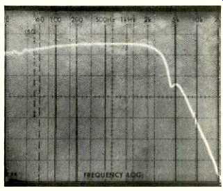
Fig. 9--Frequency response, AM section.
Use and Listening Tests
To put it simply, Larry Schotz has outdone himself this time. That old Sherwood tuner, mentioned at the beginning of this report, originally sold for around $2,000.00! But this NAD tuner designed by Schotz carries a suggested retail price of just over $300 and outperforms his earlier unit by a wide margin. Tuning is easier than on most tuners I've worked with, and the difference was even more apparent when dealing with signals having marginal levels. I picked up, with usable quality, at least eight stations that are normally so full of noise and distortion that I don't even log them as receivable in my location.
The 4150's variable-bandwidth detector feature seems to eliminate the need for the variable bandwidth i.f. stages found in much more expensive tuners and receivers, and that obviously reduces cost. Schotz was right about the relaxed center-tuning requirements too. Given a fairly strong signal, I was able to detune the 4150 by a full 100 kHz in FM without detecting any change in sound quality, noise or distortion. Try that on a tuner having a conventional detector circuit, and the sibilance and raspy peaks would make you leap from your armchair to retune (or turn off) the set.
I deliberately made some A-B comparisons between the 4150 and a conventional tuner costing about $600.00, tuning each to stations known to produce multipath distortion in my location. To make matters worse, I even rotated my outdoor antenna to emphasize the problem. I'm not going to tell you that the NAD 4150 totally eliminated the problem, but it very definitely reduced it to tolerable levels. The familiar raspy outbursts so characteristic of multipath-signal reflections occurred with great regularity on "Brand X" and only were audible during occasional extremes of modulation with the NAD 4150.
I've always had a great deal of respect for Larry Schotz's work in r.f. design. I felt that his design efforts were always pure in concept, devoid of gimmicks, and represented the state of the art. The NAD 4150 helps to reinforce my high opinion of this behind-the-scenes inventor, and I look for ward to his next breakthrough. As for NAD, they deserve a great deal of credit for having turned to the right designer when they wanted an outstanding tuner.
-Leonard Feldman
(Audio magazine, Mar. 1983, Leonard Feldman)
also see:
NAD 7130 Receiver (Equip. Profile, Sept. 1985)
= = = =