
MANUFACTURER'S SPECIFICATIONS
Phono Section Five systems available; system A, standard, has specifications as follows. Noise below 10 mV ref. at 1 kHz:-88 dB, 20 Hz to 20 kHz equivalent bandwidth. Slew Rate: 20 V per uS. Maximum Output: 6 V min. Channel Tracking: 0.2 dB typical. Input Impedance: 49.9 k-Ohms. Overload: 1 kHz, 100 mV min.; 20 kHz, 900 mV min. Other systems detailed in text.
Line Section Frequency Response: Flat ±0.2 dB, 20 Hz to 50 kHz;-1 dB at 12 Hz and 100 kHz. Maximum Output: 10 V. Gain: High, 21 dB; Low, 11 dB. Noise: Below 2.5 V, 100 dB min. Input Impedance: High, 10 k-Ohms min.; Low, 30 k-Ohms. Open Loop Bandwidth: 40 kHz. Slew Rate: 100 V per uS, min.
Prices: JC-2 system A, $1050.00; JC-2 system B, $1050.00; JC-2 system D, $1175.00; extra plug-in cards, $50.00 for system A, $175.00 for system D; case, $50.00.
The Mark Levinson JC-2 is a quite interesting attempt at producing an audiophile perfectionist's preamp. The circuitry was designed by John Curl, a competent, well-travelled audio consulting engineer.
Physically, the preamp is in two parts, the preamp itself and a separate power supply. The metal sheet preamp chassis is bent into a closed shape that forms the rear panel, sides, and front. A rack-width, two-inch-high front panel is bolted on the front of the chassis piece with the rotary control bushing nuts. Separate top and bottom pieces are bolted to the chassis to enclose the unit. All of the metalwork is black anodized aluminum. A single master PC board occupies most of the internal space inside the chassis and is mounted to the bottom cover with 10 threaded metal spacers. On this PC board are five active potted modules, miscellaneous Rs and Cs for bypassing, gain determination, and coupling functions, two plug-in equalizer boards for the phono function, and space for a JC-1SM pre-preamplifier. The five potted modules are the active circuitry for the two phono preamps, two output amplifiers, and an active power supply decoupling filter for the supply to the phono circuits. All of these modules and equalizer boards have a number of protruding gold-plated pins on each and plug into mating gold-plated socket receptacles on the master PC board.
This preamp has provision for a number of different frontend options which are installed by plugging in different equalizer boards and, in one case, the JC-1SM pre-preamp which consists of a PC board with external components and a sixth potted amplifier module. This PC plug-in fits between the two phono amplifier modules. The options are:
A. Normal Phono: 32.5 dB gain at 1 kHz. Uses system A plug-in equalizers and is for regular magnetic cartridges.
B. Normal Phono: 30 dB gain at 1 kHz. Uses system B plug-in equalizers and is for high-output magnetic cartridges.
C. Special Phono Equalization: For B&K test records.
D. Moving-Coil Phono: 60 dB gain at 1 kHz. Uses JC-1SM pre-preamp with phono amplifiers. Uses D or D1 equalizers.
E. Strain Gauge: Provides equalization and d.c. excitation for certain strain gauge pickups.
F. Flat Response: Provides for flat gain of front end for microphone and other flat-gain applications.
Note that only one option can be operational at a time. The unit tested was supplied with two A equalizers, a JC1SM, two D and two D1 equalizers. The D equalizer provides nominally flat moving-coil RIAA equalization and the D1 rolls off the high-end response above about 7 kHz to offset the rise in this region which some moving-coil pickups exhibit.
On the front panel are four rotary controls, four miniature toggle switches, and a LED power-on indicator. From left to right, the controls are rotary selector switch, tape monitor toggle, tape 1/tape 2 toggle, left balance rotary switch, pilot, right balance rotary switch, mono-stereo toggle, high-low gain toggle, and the rotary level control. The gain control is a high-quality dual Waters unit that features close tracking between sections and very low or non-existant nonlinear distortion. There are no tone controls or filters on this preamp.
The rear panel has all of the signal input and output RCA jacks and male and female four-pin XLR connectors, the male being used to receive power from the external power supply and the female presumably being available to power some other piece of gear that uses ±15 V d.c.

Fig. 1-Back panel view.
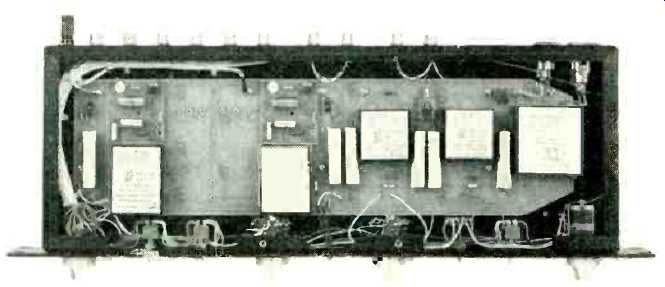
Fig. 2-Internal view.

Fig. 3-Simpliified schematic.

Fig. 4-Moving-coil circuit.
The power supply is in a black anodized aluminum case and is fully potted. A three-foot a.c. cord and a five-foot power cable serve to connect to line and preamp and allow enough separation so that no hum is induced in the preamp from the power supply. Component parts appear in general to be high quality with resistors being 1% metal film types and capacitors being either dipped mica, mylar or better, and tantalum, with the exception of four aluminum electrolytics on the JC-1SM plug in, which are used for power supply filtering. Teflon wiring is used throughout.
Circuit Description
Starting with the phono section, the components enclosed within the dotted lines on Fig. 3 are on the A equalizer plug-in boards. The phono amplifier module itself is a low-noise class-A complementary push-pull amplifier-the actual schematic is proprietary and therefore is not available for discussion The overall circuit functions as a non inverting equalizer-amplifier with a closed loop gain of about 33 dB at 1 kHz and RIAA equalization accomplished by the RC network in the feedback loop. Quiescent current drawn by these modules is rather high, being about 65 mA at ±15 V d.c. A good part of the quiescent current must be in the output stage in order to gracefully drive the feedback loop at high frequencies since the impedance level of the network is rather low-about 160 Ohms at 20 kHz.
When the JC-2 is set up for moving-coil pickups, two D series equalizers are installed along with the JC-1SM pre-preamp board. The equivalent interconnection of the JC1SM, equalizer, and phono amplifier is shown in Fig. 4 with a D1 equalizer installed. The D equalizer is identical except that the input low-pass filter is absent. In this configuration, the impedance level of the RIAA series-feedback network is scaled up five times and the shunt feedback resistor is down to ten Ohms. These network values indicate a closed-loop gain of about 60 dB at 1kHz. The special input stage in this configuration is included in the feedback loop which is a good idea and is one of the first circuits to do so; it could have been designed as a separate flat-gain block ahead of the phono preamp, as has been done by several Japanese manufacturers. Both the normal phono and moving-coil gains are low compared to normal practice by some eight dB. The Mark Levinson people apparently do this in order to increase input signal acceptance, which is a legitimate design choice.
The output amplifiers in the JC-1 have a nominal closed loop gain of 21 dB when the balance controls are set to the 0 dB mark. This preamp has a separate balance control for each channel. The controls vary the series-feedback resistance around the output amplifiers such that the gain changes in 1 dB steps. The most counterclockwise position mutes the output by grounding the wiper of one section of the balance switch. Low gain in the output section is accomplished by adding 20 kOhm in series with the 10 kOhm volume control. This inserts 10 dB attenuation ahead of the output amp, resulting in a net 11-dB gain for high-level inputs.
High-level input impedance is obviously affected, being 30 k-Ohms at low gain and 10 kOhms for high gain. When the mono mode is selected, the wipers of the volume control sections are tied together and 10 kOhms is placed in series with the feed to each volume control section. The 10 kOhms addition causes the volume to drop noticeably when in mono. The 10 kOhms resistors were probably considered necessary, however, to prevent direct shorting together of the left and right source signals when the volume control is at maximum.
A switch mounted on the master PC board allows direct or capacitor coupling of the output of the line amplifiers to the main preamp output jacks. One is supposed to capacitor couple to d.c. responding power amps and direct couple for a.c. coupled power amp inputs.
The power supply delivers regulated ±15 V d.c. up to 300 mA. The JC-2 draws about 250 mA, leaving some 50 mA available to power something else.
Listening Tests
The JC-2 was first listened to as a phono preamp only, connected for normal phono gain. A Fidelity Research FR-1 Mk II cartridge was used with the reviewer's own pre-pre amp. The output signal from Tape Out was fed into a 50-kOhm dual volume control and then into a power amplifier.
Listening was done with Dahlquist DQ-10 speakers, kindly on loan from the manufacturer for these tests, and Stax SR-X MkII headphones. Under these conditions, the sound of the phono preamp was quite good. Overall definition and openness were excellent, with just a very small bit of the irritation and edginess in the highs that has been present, almost always to a greater degree, in every solid-state circuit listened to so far. The transparency of the sound was judged superior. Curiously, when including the output section, the sound became noticeably softer with less irritation and high-frequency edginess. All in all, a very creditable performance.
The unit was then set up for moving-coil operation. The sound of the unit was about the same as above, and again, it sounded smoother when the output amplifiers were used.
The unit in this form was also listened to by several other critical listeners and the general consensus was that it sounded quite good though the trace of high-frequency edginess was also noticed by these people.
All of the functions worked well with the exception of the level drop when in mono which was mildly annoying. The separate balance controls were judged to be a very handy feature, and noise with moving-coil operation was outstandingly low. This is a definite contender for the state-of-the-art crown among a very few other preamps.
(Editor's Note: This listener used the JC-2 with a Shure V-15 III, a freshly peaked Sony TC-277-4 open-reel recorder with second-generation masters, a Heath AA-1640 amp, and Duntech DL-15 speakers. Sound from records was judged outstanding, with a superior definition not found with any preamplifier listened to so far. Sound from tape was similarly superior, characterized by an openness and freedom. Particularly appreciated was the absolute dead quiet of the unit, along with a subtle sense of "accuracy" which gave choral selections a new sense of separation and location not found with preamps previously tried. Instruments such as banjos, guitars, and mandolins seemed substantially more life-like with this unit, while piano music appeared to have greater clarity and strength.
Though there is a certain lack of flexibility in the controls of the JC-2, in that the unit has no filters or tone controls, an unusual and worthwhile feature is its ability to take the output of a moving-coil cartridge directly with the suitable boards.
Overall, then, this unit must be judged as the best preamp thus far reviewed, and certainly as one which any newcomer would have to push aside to come away with state-of-the-art honors. -E.P.)

Fig. 5--CCIF and SMPTE IM and 20-kHz total harmonic distortion levels.

Fig. 6--RIAA noninductive-source equalization error.

Fig. 7-- Normal-phono square-wave responses, with inputs adjusted to overlay
outputs. Top, 40 Hz with Hi-Z and 10kOhm loads; middle, 1 kHz, and bottom,
10 kHz. (Scales: all 0.5 V/cm; top, 5 mS/cm; middle, 200 uS/cm; bottom,
20 µS/cm.)
Measurements, Phono Section
Measurements were first made in the normal phono mode using the A equalizer boards. The 1 kHz gain was found to be 43X in both channels or 32.7 dB, a hit above the specified 32.5 dB. The 20-kHz THD, CCIF two-tone difference distortion, and standard SMPTE IM are plotted versus phono output voltage in Fig. 5. All of these distortion levels are very low and, in view of the low phono gain, are likely to be low in practice with high-output magnetic cartridges. Of interest here is the fact that the distortion products are essentially second and third order harmonics. The RIAA equalization error with a non-inductive source is plotted in Fig. 6. The low-frequency rolloff with a 10 kOhm load is due mainly to the 2µF output coupling capacitor used. The effect of non-ideal 47-kOhm input resistance and possible interaction of reactive sources on the feedback equalization was checked using representative low- and high-inductance magnetic cartridges. With the high-inductance source, the response was up about 0.9 dB at 5 kHz, up 1.4 dB at 10 kHz, up 0.7 dB at 15 kHz, and down 0.25 dB at 20 kHz. With the low-inductance source, response was up about 0.5 to 0.6 dB from 3 to 20 kHz. This behavior is generally in line with other circuits though most other circuits roll off the last octave a little more than this one with a high-inductance source.
Slew rate of the phono section was measured at 2 V peak to peak, and it was found to be 20 V per µS, which appears to be substantially faster than most other phono sections.
Equivalent input noise as a function of measurement bandwidth was found to be 0.38 µV and 0.35 µV for left and right channels in a 20 Hz to 20 kHz bandwidth. This noise was composed of a low amount of identifiable line harmonics and lower frequency 1/f noise. These input noise voltages are equivalent to a signal ratio of 88.4 and 89.1 dB below 10 mV at 1 kHz. In a 400 Hz to 20 kHz band, the input noise for both channels was 0.23 µV. These noise measurements qualify this preamp as the quietest unit so far measured.

Fig. 8--High-level frequency response; note break in curve at 100 Hz/10
kHz.

Fig. 9--Output section square-wave responses. Top, 20 Hz, d.c. coupled
and a.c. coupled with 47and 10-kOhm loads; bottom, 20 kHz. (Scales: top,
10 mS/cm and 1 V/cm; bottom, 10 µS/cm and 1 V/cm.)

Table I--Normal-phono overload versus frequency.

Table II--Moving-coil gain at 1 kHz.

Table III--Moving-coil input noise and signal-to-noise ratio re 1 mV versus
equalizer and measurement bandwidth.

Table IV--Moving-coil overload versus frequency.

Table V--Output-section noise versus bandwidth, gain, and volume control
position.
Scope pictures of pre-equalized square wave response are illustrated in Fig. 7. Equivalent input bandwidth is limited to 50 kHz for these tests in order to represent some realistic bandwidth from a real cartridge. The upper trace shows the effect of a 10 kOhm load on low frequency tilt-the greatest tilt being for the 10 kOhm load.
Phono overload versus frequency is tabulated in Table I. Overload was visually judged on a 'scope and was the onset of clipping on the negative half cycle at all frequencies.
Crosstalk between channels was measured on a pre-equalized basis and found to be greater than 80 dB down from 20 Hz to 11 kHz, decreasing to 74.6 dB at 20 kHz. These are excellent measurements on this test. S/N at 1 kHz re 10mV was 92.8 dB. The preamp was next set up for moving-coil operation.
The 1-kHz gain was measured with a one-ohm source for the D and D1 equalizer plug-ins. Results are shown in Table II. Equivalent input noise versus bandwidth for the two equalizers are tabulated in Table III. The noise level for the D equalizer in a 400 Hz to 20 kHz band is an absolute record of achievement in this reviewer's experience! Noise with the D1 equalizer is higher because of the extra 10-ohm resistors in the input circuit used to achieve the high-frequency rolloff. The 20 Hz to 20 kHz noise was dominated by 1/f low frequency components with line harmonics being conspicuously absent. This is the real reason for the external power supply-to get rid of hum field radiation problems of a power transformer in the preamp enclosure when using a moving-coil phono stage. RIAA equalization error is plotted in Fig. 6 for a 10-ohm source with the D and D1 equalizers.
Considerations of source inductance effects aren't relevant with moving-coil pickups, as all of these pickups (at least the ones seen by the reviewer so far) are virtually purely resistive in impedance to well beyond 20 kHz.
Standard IM was measured for this configuration and was found to be less than 0.01% for output voltages of 5 V rms or below. It was noticed that with D equalizers installed the system became unstable when driven into clipping. Everything was fine just below clipping but just at the onset of clipping, the output started a low frequency oscillation.
With the D1 equalizers in, the low frequency oscillation disappeared. Apparently, the added input network in the DU help this minor problem. When the output clips and the minus half cycle clips first, a high-frequency nonsinusoidal oscillation of about 62 kHz appears on the clipped portion of the waveform. It is not known at this time whether this is characteristic of the design. THD versus frequency at 5 V rms or below was less than 0.01% from 20 Hz to 20 kHz. Overload versus frequency is indicated in Table IV. Overload was the visual onset of clipping which precipitated the above mentioned instability. Both IM and THD were relatively unaffected by output loading for loads of 10 kOhms or higher.
Waveforms for pre-equalized square waves for the D equalizer are substantially the same as in Fig. 7 with the exception that there is more low-frequency tilt. The 40-Hz tilt with a high impedance load is more like the 10 k loading on the normal phone. The 10 kHz response with the D1 equalizer is slow and what one would expect of a 20-kHz low-pass filter.
High Level Section
Gain of the output section for input to Tuner, balances at 0 dB, and volume control fully clockwise, was 3.8X or 11.6 dB for both channels with gain set for low. With gain set for high, it was 11.5X and 11.3X for left and right channels which works out to 21.2 and 21.1 dB. Frequency response of the high-level section is plotted in Fig. 8. As can be seen, the response above 300 kHz is slightly better with the gain set at low.
Output noise with shorted inputs versus gain, volume control position, and bandwidth is in Table V. These output noise levels are satisfactorily low for the JC-2.
IM distortion was measured as a function of output voltage and found to be less than 0.01% for output voltages of 3 V rms or below, rising to 0.027% at 5 V, and 0.073% at 7 V rms output. Measurements of THD versus frequency and output voltage resulted in a distortion level of less than 0.01% between 20 Hz to 20 kHz for outputs of 6 V rms or less, about 0.01% at 7 V, and 0.043% at 10 V output. Both IM and THD were essentially unaffected by loads of 10 kOhms or greater.
An attempt to measure the slew rate of the output amplifier by usual methods was made. A slew rate of 300 V per µS is the same as 30 V per 0.1 µS, which means that the output amplifier should go from, say,-15V to +15V in 0.1 µS. A fast rise time square wave was used to drive the output amplifier to about 30 V peak to peak and was just below clipping. The edge transitions of the output waveform were exponential in shape, indicating that stewing wasn't occurring, and the rise and fall times were 1.5 µS. If the output amp was severely overdriven, the transitions became much faster-approaching 30V in about 0.2 µS. This appears to be invalid, as slewing generally refers to internal nonlinearity of the device under test during fast level transitions and not to steady state.
Mark Levinson Audio measures the slew rate of the output amplifier by the following manner. A sine wave test frequency, 4 megaHertz, is applied to the output amplifier and the output level driven up to 20 V peak to peak, the limit of our oscillator. With this amplitude and frequency, it then becomes possible to demonstrate an equivalent slew rate of 250 V per µS.
'Scope pictures of square-wave response of the output section are shown in Fig. 9. The upper trace shows the response for d.c. output coupling and a.c. coupling with a 47 kOhm load and a 10 kOhm load. The 20-kHz response indicates a rise time in the region of 1µS. Crosstalk between channels was measured and found to be greater than 80 dB down from 20 to 175 Hz, decreasing to -70 dB at 600 Hz,-60 dB at 2 kHz, -50 dB at 13.6 kHz, and -40 dB at 20 kHz.
In conclusion, the JC-2 is a beautifully made piece of gear that may well find its way into professional application. Long term reliability of this unit is likely to be very good. It should be of more than passing interest to well-heeled audiophiles who would like to add a piece of top-quality gear to their systems.
-Bascom H. King
Manufacturer's Comment: One of the big problems with "state-of-the-art" audio today is that most of the program source material available is loaded with distortion of various types, either by accident or by design. (We certainly agree with this point. -Ed.) One of the consequences of this is that sometimes a less accurate component can mask or veil some of the problems in the source material, and for this reason a superior or more accurate component will not always make the music sound better.
We designed the JC-2 to be as accurate as possible, not to provide any subtle colorations which might make program material sound "better," and we feel the result is a practical and beautiful instrument for people who want excellent sound quality and can do without certain conveniences and flexibilities offered by other commercially available designs.
-Mark Levinson Audio Systems
(adapted from Audio magazine, Apr. 1976)
Also see:
McIntosh Model C-27 Stereo Preamplifier (Equip. Profile, Sept. 1978)
McIntosh Model MR-78 FM/Stereo, FM Tuner (Feb. 1977)
McIntosh Model C-28 Stereo Preamplifier (Equip. Profile, Nov. 1976)
= = = =