by Walter G. Jung, Mark L Stephens, and Craig C. Todd
[Portions of this article are adapted from "Slewing Induced Distortion in Audio Amplifiers" by the authors in The Audio Amateur, Feb., 1977 ( P.O. Box 176, Peterborough, N.H. 03458), part of an article series which is available in book form. Portions were also adapted from the authors' article "Slewing Induced Distortion- Its Effect on Audio Amplifier Performance, with Correlated Listening Results," Audio Engineering Society Preprint No. 1252 from the May, 1977, convention. (See bibliography references nos. 33 and 34.) Copyright 1979 by Walter G. Jung, Mark L. Stephens, and Craig C. Todd.]

In this series of articles we hope to shed useful light on the high-frequency performance of amplifiers. Modern operational amplifiers and circuits of similar topology have an inherent Slew Rate (SR) limit, and they will produce distortion as the output Signal Slope (SS) approaches this limit. We refer to this distortion as Slew Induced Distortion (SID).
If an amplifier is driven into slew-rate limiting gross distortion will be produced. This is analogues to driving an amplifier into amplitude clipping, which also produces gross distortion. The distortion produced by driving an amplifier towards slew-rate limiting has also been described as Transient Intermodulation distortion (TIM) [3,8,9,17,18,51,56].
Until recently [33,34] there has not been a thorough study of this distortion. Therefore, this series is intended to be a comprehensive overview and explanation of SID. We will explain how and when SID is produced by an amplifier, and measurement techniques for and typical measurements of this distortion will be described. The results of a listening test for SID will be discussed, and the results of a theoretical calculation of SID in a 741 op amp will be shown and compared with measurements. Some reasonable design criteria will also be reviewed. Above all, we will attempt to give a good overall perspective of this subject so that the reader will be able to judge its relevance to his or her own situation.
Before discussing how SID occurs within amplifiers, it is necessary and appropriate to first consider how the slew rate itself is related to an audio signal. A sine-wave audio signal has definite and measurable parameters, namely its amplitude and frequency. However, a somewhat more subtle parameter (and one germane to this issue) is the slope of the signal, as is determined by its amplitude and frequency. A simple relationship which defines the signal slope (SS) of a sine wave is the equation
SS = 2πpf (1)
where Vp is the peak signal voltage, and f its frequency. Sometimes this equation may be seen written in terms of slew rate (SR) [20,21,22,29,30,54], however we wish to clarify the point here that signals in themselves have no inherent slew limit, or maximum allowable slope, as do amplifiers. Therefore, we will use the terminology of SS to describe the slope of a sine-wave (or other) signal and SR to describe the slew rate of an amplifier. Note that this is an important distinction, as an amplifier has a defined SR; which is (by very definition) its maximum output-voltage rate of change, or slope, as set by its design. It is a defining performance limit for that amplifier, just as power output is (or any other basic performance parameter, for that matter).
The reader should note that this equation may be manipulated into an expression in terms of a frequency (f), for a given signal slope and peak voltage; for instance:
f=SS/2 pi V p. (2)
When the relation is thus used, and the particular SS under discussion is the slew rate limit of a given amplifier and Vop its peak output voltage, it would appear as
fp= SR/2π Vop. (3)
This expression yields a power bandwidth, fp, which is determined by the amplifier SR and the peak output voltage, Vop. Generally, fp is understood to be the bandwidth for a 1 percent THD limit. Note that fp is directly proportional to SR and inversely proportional to Vop. The practical significance of this is that high output-voltage amplifiers require more SR to maintain a given distortionless bandwidth.
Also, an important distinction to be made is that power bandwidth defines an entirely different form of bandwidth than does the more familiar small-signal bandwidth, and the two terms should never be confused. Exceeding the power bandwidth of an amplifier causes gross distortion; exceeding its small-signal bandwidth results only in a frequency response rolloff [37].

Fig. 1--Mixed square/sine output from amplifiers with and without TIM. General
conditions: 5-kHz square wave and 40-kHz sine wave
Fig. 1a--Strong TIM, sine wave missing on waveform transitions, slewing evident. (Scale: 10 V/div.) Fig. 1b--little or no TIM, waveform is a linear sum of sine and square waves. (Scale: 1 V/div.)
Fig. 2--Amplifier square-wave responses with and without slew limiting.
Fig. 2a--Slew limiting (10 kHz, 10 V p-p).
Fig. 2b--No slew limiting (10 kHz, 1 V p-p).

Fig. 3--Inter-relationship of amplifier response, feedback, and SID. Fc
is the small signal bandwidth which varies for different gains. Fp is amplifier
full-power bandwidth which is independent of gain (for a given output level).
SID and TIM--Which is Which and What Do They Mean?
Unfortunately, many of the popular explanations serve to confuse rather than clarify the issue, and this short preparatory discussion will, we hope, clarify some of these points to the reader.
"TIM" stands, of course, for transient intermodulation distortion, sometimes called simply "transient distortion." If this name is taken in a literal sense, it implies a distortion mechanism which produces intermodulation when subjected to transients. A point to be noted is that if the term were understood literally, this would imply transients of both high and low frequencies and/or high or low operating levels. In other words, all transients.
In actual practice, however, transient IM occurs only for signals with simultaneous high level and high frequencies- not lower levels or lower frequencies. The key parameter of such signals is that they are characterized by high signal slopes, not just high frequencies or high levels. Neither high frequencies nor high levels in themselves necessarily result in distortion, unless their combination is such that a high effective SS is produced.
High SS waveforms are not confined solely to transient waveforms. It just so happens that musical signals which exhibit high signal slopes more often are transient in nature- a fortissimo cymbal clash, for instance. Thus, TIM is probably a descriptive term for the distortion as it occurs on musical waveforms, but the term is not totally descriptive of the distortion mechanism itself [33, 34, 44, 52].
TIM is actually generated when the SS approaches or exceeds the amplifier SR. Thus, a more easily understood term as to what actually happens would be one which relates both to SS and SR. In an amplifier, distortion is produced when the output voltage SS approaches or attempts to exceed the SR, as the amplifier limits (clips) for such a circumstance. This can happen for either transient or steady-state signals [33, 34, 52] if they have a sufficiently high SS. Thus we feel a more descriptive term to describe the mechanism is Slew Induced Distortion [33, 58] as it is distortion induced either by the onset of or actual slewing. Other descriptive variations of this terminology are seen in print, such as "slew rate distortion" and "slewing distortion," and mean essentially the same thing [11].
Effect of Excessive Signal Slope On Amplifier Performance
A demonstration of the sensitivity of amplifiers to SS is contained in the two waveform photos of Fig. 1. Figure la shows a mixed square/sine wave signal combination, where the level and risetime of the square wave are such that the SS is greater than the amplifier SR. For this particular output voltage, then, slew limiting is produced on the square-wave edges, causing the momentary disappearance of the sine wave. Note in particular the square wave transition in the center of the screen. This is, of course, a strong case of TIM, which is induced by the condition of slewing.
In 1b, the same signal is shown at a reduced level, and, as can be noted, the slew limiting is gone, as the waveform indicates simply a linear sum of the sine and square wave.
The point being made here is that the distortion is not being caused so much by the transient as it is by the high SS (in Fig. 1a). Thus, it should be appreciated (in a qualitative sense) that SID (or TIM) is a distortion which is level sensitive in terms of both amplitude and frequency (since both affect SS).

Fig. 4--Relative relationship of fc and fp, and the resulting effect on
SID. General conditions: 5 kHz square wave, 20 V p-p.
Fig. 4a--Fc, >fp; slewing evident.
Fig. 4b--Fc2- fp; some slewing on highest SS.
Fig. 4c--Fc3<fp; no slewing evident.
This factor is demonstrated in another way by the square-wave response photos of Fig. 2. In Fig. 2a, a 10V p-p square wave is shown, and, as can be noted, the amplifier is slewing, as evident by the linear rising and falling waveform edges. In 2b, the waveform is at a lower level, and here the square wave is reproduced without slew limiting. This is evident by the exponential shape of the waveform edges, which is an indicator that the amplifier is operating linearly [15, 36, 37]. It is in actuality operating as a low-pass filter, as is defined by its small signal bandwidth, fc.
A square wave passed through a single-pole filter will exhibit the general waveform shape of Fig. 2b, and such a waveform at the output of an amplifier is a qualitative indicator that no slew limiting is present. At progressively higher voltage-output levels, slew limiting may set in (as in 2a), and the waveform then takes on the ramp-like slopes [15, 37, 50, 63].
This is incidentally an excellent check to make on an amplifier if possible, increasing output square waves. If the exponential waveshape holds true for increases in level up to the rated output, the amplifier is behaving optimally, as it cannot be made to slew for any realistic signal conditions [11, 43]. For this to be true, the power bandwidth must be greater than the small-signal bandwidth [45] which in turn says that the amplifier is guaranteed free from internal over load due to excessive SS. An amplifier can be designed for a defined small-signal bandwidth either by use of an input low-pass filter or appropriate feedback connections to constrain output SS below the SR. Further details of this from a design standpoint are contained in several references [11, 43, 45] and are also discussed later on.
The Effect of Feedback on SID
One of the popular explanations for the cause of TIM and SID is said to be excessive negative feedback used around audio amplifiers [3,4,6,7,8,9,10,13,48]. In fact, this appears to be one of the more volatile parts of the issue, even to the extreme that already there have appeared statements in the literature calling for maximum feedback factors on the order of 12 dB and amplifiers advertised as having "zero feedback." The general argument advanced is that increasing negative feedback increases the susceptibility to TIM, and optimum feedback factors are said to be on the order of 30 to 40 dB.
It is interesting to consider how changes in feedback will affect the performance of an amplifier. There are certain aspects of the "less feedback is better" school of thought which have definite merit, but the entire situation must be considered for a true and complete perspective.
Consider a fixed gain-bandwidth amplifier open-loop response, as illustrated in Fig. 3. This amplifier has a unity-gain frequency of 1 MHz (such as a 741) and a full-power bandwidth of 10 kHz (at full output). Suppose we examine its susceptibility to SID for gains of 20, 40, and 60 dB, and at full output level. The small signal bandwidth (fc) for these three conditions will be 100 kHz, 10 kHz and 1 kHz, respectively [30]. However, for each condition of feedback, the full-power frequency (fp) remains at 10 kHz. Then, for the 20-dB (heavy feedback) gain condition SID is definitely possible, for output frequencies of 10 to 100 kHz. For 40 dB of gain, fc is equal to fp, and slight SID is possible. For 60 dB of gain, fc is less than fp, so SID is not possible.
A demonstration of this is contained in the photos of Fig. 4, taken from an IC op amp operating fairly close to the conditions of Fig. 3. For this device fp is 17 kHz, and Fig. 4a shows a square wave for the condition where fc is greater than fp; slewing is evident. In 4b, fc is equal to fp, and some slewing is noticeable at the initial rise of the square wave where SS is highest. In 4c, fc is less than fp and no slewing is evident. In all three instances, the experiment follows what the Bode diagram predicts.
The reason that slewing is not evident for the high-gain, low-feedback condition is because the amplifier output SS is severely curtailed, due to the very low small-signal bandwidth. This is another demonstration of the point made above that slewing can be prevented by making fc less than fp. For a fixed gain-bandwidth amplifier, as just demonstrated, this generally says that less feedback can prevent or re duce susceptibility to TIM or SID, as it reduces fc in relation to fp, or lowers the output SS in relation to amplifier SR. This is however hardly the optimum manner to arrive at this objective, as it will most certainly result in a generally noisier and more distorted amplifier, as well as possibly insufficient bandwidth. If fc is to be maintained less than fp, it should be done by another method, obviously.
Another view on the "less feedback is better" argument is to consider an amplifier which is compensated (optimally) for a higher gain (less feedback) condition. Due to fundamental feedback stability criteria, such an amplifier will have proportionally less-compensation capacitance necessary. The smaller capacitance for less feedback then allows a higher SR to be realized by the amplifier, and so it is less susceptible to TIM or SID, as it can now handle greater SS waveforms linearly. In this case, the improvement is an indirect result of less feedback, a point which should be appreciated fully--it also results because the SR is raised.
These points are somewhat subtle, and we do appreciate that a fair amount of semantics are involved in the discussion which accompanies this issue. There are, however, several key points which are clear and should be made.
Since the limited SR is the cause of the distortion, it follows that design means which improve amplifier SR will lower distortion as a general result. (While this is generally true, there are notable exceptions, such as slew enhanced devices, which will be discussed later.) Feedback is certainly involved in the overall issue, but intimations that there is a fixed magical upper limit to feedback factors have no sound engineering basis to our knowledge. Given sufficient SR (and an otherwise linear amplifier), there is no inherent reason why 60 to feedback The ultimate stability limit will, in practice, confine it to less than this as a natural consequence of usable gain-bandwidths, at least at audio frequencies.
Another part of the semantics issue comes to play with the argument that less feedback in combination with a more linear open-loop characteristic is desirable towards prevention of TIM. Essentially this is true, because without a high degree of overall feedback, less compensation (if any) is needed, and SR goes up as a result. However, local feedback around a stage is still feedback, and if bipolar transistors are used, it hardly seems possible to get truly excellent open-loop linearity without a lot of feedback, since their voltage transfer is basically exponential. So the argument should perhaps be oriented towards a closer definition of what kind of feed back, as well as its degree.
To get back to the more conventional amplifier, the point has been made that it is SR which is the fundamental predictor of SID (and/or TIM), and amplifier improvements which increase SR generally lower SID (and TIM).
The remaining low TIM criteria, wide open-loop amplifier bandwidth, involves semantics also. Taken literally, an open-loop bandwidth of 20 kHz (as commonly specified) [1,2,3,4,6,7,8,10,14] will be interpreted to mean 20 kHz small signal bandwidth. What is really important is a 20 kHz (or more) power bandwidth, which will minimize or eliminate slew limiting [33,34,39,45,52].

Fig. 5a--Amplifier model. R
Fig. 5b--Amplifier frequency response.
Amplifiers can be designed for 20 kHz (or more) open-loop bandwidths, but often with a severe penalty of low-frequency linearity and gain accuracy [40,45]. By results from several different forms of tests, there appears to be no fundamental necessity for a wide open-loop small-signal bandwidth, given a power bandwidth sufficient to eliminate slew limiting. Several specific test results discussed later on clearly demonstrate this point.

Fig. 6a--Real amplifier.
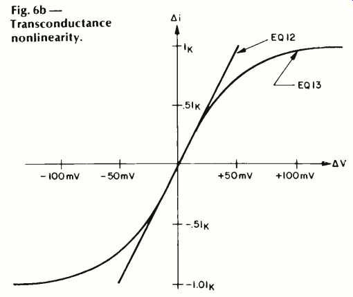
Fig. 6b--Transconductance nonlinearity.

Fig. 7--Amplifier with feedback.
Analysis of The Slew-Induced Distortion Mechanism
It is of fundamental importance to understand the various distortion sources in amplifiers, such as the SID mechanism of interest here. In this discussion we will mostly deal with operational amplifier circuits, but since many present-day power amps are of similar topology and are subject to similar physical laws, the discussion and data will be relevant to them as well.
Figures 5a is an idealized model of a typical operational amplifier [20, 21, 22, 24]. Its input stage is a voltage-to-current converter or transconductance stage, characterized by the parameter gm. The output current of this stage (delta i) is simply
Ails=gmeV(,). (4)
The second stage of the amplifier is output voltage an integrator, with an (Vo)
Vo(t)= ,. láV(,)dt. (5)
The resistor R is responsible for the finite d.c. gain of the amplifier. At low frequencies the open-loop gain is
Ao=gmR. (6)
The open-loop frequency response begins dropping (Fig. 5b) at a frequency
ωo1/RC. (7)
Since for audio circuits we have no great interest in the amplifier gain at d.c., it is much more convenient to neglect R (as in equation 5) and work with the unity gain bandwidth (wu) which, due to the integrator's-6 dB/octave response, is equal to the gain bandwidth product.
wu=A((.,)xw
=A,, w0=gm/c. (8)
Referring to equation 5, we have:
V) 1 dVo1,). (10) wu dt (9)
Thus, for an amplifier with a six dB/octave frequency response, the amplifier can be characterized simply by its unity-gain bandwidth or gain-bandwidth product. Out next step is to examine the differential input voltage as a function of the output voltage. Differentiating equation 9 we have
Vow= wu tiVt,)dt. (10)
This highly important result clearly shows us that the instantaneous differential input voltage of an amplifier is directly proportional to the slope of the output voltage, with 1/wu as the constant of proportionality.
If we now look at an actual amplifier, we will understand what SID really is. Figure 6a is a very simple real amplifier which will serve to demonstrate this. Q1 and Q2 are the differential input pair, and Q3-Q4 form a current mirror, this Q1-Q4 stage is our transconductance amplifier with a transconductance of
gm=lk/2V1 (11)
where Vr=K1/q (26 mV at room temperature). Q5, with its current source load IA, forms our integrator, in concert with C. We will neglect the finite d.c. gain produced by R, inasmuch as it has no bearing on omega-u (see above). Ideally the g_m stage output current (delta i) is
delta i(o=g,,AVol_1k(AV())/2Vr (12)
However, this is only true when AV is small. The exact transfer expression for this input stage is [23].
delta il,l=lk tanh (AVI,)/2V1). (13)
As this expression shows, the transconductance stage is linear only for small signals, and thus will produce distortion for high output currents, when AV is large. Equations 12 and 13 are plotted in Fig. 6b and illustrate this point more clearly.
The maximum output current (limit) from our input stage is 1k. This determines the maximum rate of change of V,,, which is the slew rate of our amplifier. This is simply:
SR = lk/C. (14)
How close we are working to the SR is:
SSoutput/SR = delta i/lk. (15)
This relation is one important and useful, as will be seen. The ratio SS/SR we will here define as the slew rate ratio (SR ratio), which relates the output SS to the amplifier SR.
This ratio is easily measurable from outside the amplifier with a differentiator, Ai/Ik = (1/SR) (dVn/dt). (16)
Figure 6b graphically tells us that operating with a SR ratio
>0.25 (or Ai>0.251k) will produce some obvious distortion.
This is equivalent to saying that operation at greater than 25 percent of the amplifier's SR will produce distortion. This distortion depends solely on the SS of the output, hence our use of the term "Slew Induced Distortion." The amplifier is producing distortion by being forced towards its SR limit; the distortion is slew induced.

Fig. 8--A 748 op-amp operating under various conditions detailed in the
table.
Table I--Operating conditions for 748 op-amp.

So far we have been talking only of the amplifier with no mention of feedback and we have been discussing the open loop performance. Amplifiers are rarely used open loop, so we must turn our attention to the effects of feedback on amplifier performance. An important point to keep in mind as we discuss feedback is that feedback networks are placed around an amplifier and have no direct effect on its internal performance. Feedback alone will not effect the validity of any of the equations developed above. It will, however, under certain signal conditions, cause these relationships to be taxed, creating a SID-producing situation. This statement will become more clear with subsequent discussions (if not al ready so from the preliminary discussion).
As is well known, feedback reduces distortion. Let's take a qualitative look at how this happens. A simple feedback net work has been placed around our amplifier in Fig. 7. The differential input voltage is

This is the error voltage which we would like to be zero, but it will be
non-zero if V. contains a gain or phase error, or distortion. If we operate
the amplifier near its slew limit, we know that the amplifier transfer characteristic
is very non linear (see 6b). The feedback will reduce this non-linearity
from Vin to Vout, but it will necessarily still exist from delta V to Vout.
If the feedback is doing its job and producing a relatively clean signal
at Vout, then it follows that the signal delta V must be distorted. The
distortion of AV must be of the proper magnitude and phase to compensate
for the amplifier's internal nonlinearity, if it is in reality reducing
distortion. A qualitative insight of this is contained in the waveforms
shown in Fig. 8. These are pictures of the performance of a 748 op amp,
compensated to unity gain by 30 pF and operated as shown in Fig. 7. The
amplifier had the following performance (measured before the experiment):
ft = omega t /2 pi
= 1.5 MHz
SR = +0.97, -0.91 V/ uS.
The amplifier was operated at its full rated output swing of 20 V p-p. Two test frequencies were used, 12.7 kHz and 19.1 kHz. At 20V p-p (10V peak) these frequencies produced signal slopes of ±0.8 V/ uS and ±1.2 V/ uS respectively. These two frequencies were applied to the closed-loop amplifier, for signal gains of 1 and 10. For either gain condition, the output was a visibly clean sine wave for the 12.7 kHz, ±0.8 V/ uS signal (not shown). However, the 19.1 kHz, ±1.2 V/ uS signal drove the amplifier into slew limiting, and this is shown in Fig. 8b. The output slewing waveform was visibly the same for either gain. Table I summarizes and identifies the conditions and results shown.
The important, point to note from this is that the op-amp input, AV, becomes highly distorted in an attempt to linearize the response of the closed-loop amplifier. In 8a and 8d, for example, AV is just beginning to become non-linear, but is still relatively low in level. As the maximum slew rate is exceeded, this process breaks down and the error voltage abruptly increases, as can be noted in 8c and 8e (note the different scale factors for AV). Operation at the lower gains (more feedback) yields lower distortion operation, and al lows low-distortion operation closer to the slew rate limit.
There is nothing particularly unique about SID in audio amplifiers. It can be measured, calculated, and improved upon by using standard techniques that have been available for some time [57]. The only elusive aspect of this form of distortion is that rather than occurring on a peak magnitude (like clipping), it occurs on the rising or falling edge of the waveform, when the SS approaches or exceeds the amplifier SR. This is due to the fact that the dominant non-linearity in the circuit, the transconductance of the input stage, is followed by an integrating stage. Thus in Fig. 5, if the transconductance stage were overloaded and producing clipped square waves of current output, the integrating stage would transform these square waves into triangle waves at the output. The triangle wave is the ultimate example of gross slewing distortion, and its presence is a visible verification that the amplifier is operating open loop during the slew interval(s).
Although slew limiting is most often encountered in amplifiers due to internal IC relations, such as have been just described, it can also occur due to output-current/load-capacitance rate limiting, with the end effect being similar [33, 34].
This type of slew limiting can occur for example in RIAA equalized preamps which cannot adequately charge frequency-shaping capacitors [33, 41] or power amplifiers which cannot drive capacitive loads due to protection circuitry [33].
The distortion products produced by SID are measurable either by methods of THD [16], two-tone high-frequency IM, or TIM [14,33,34, 51], and in all cases they become significant as the amplifier's inherent SR is approached by the output signal slope.
Representative results from these test methods are discussed in Part II of this series. In this next installment, sample data from different types of distortion tests are presented consisting of total harmonic distortion (THD), two-tone-difference intermodulation distortion (IM), and the recently proposed test for TIM [18]. Some of the relative merits of these measurement techniques will be discussed, and it will be seen that while they are all useful to the detection of this distortion, there are differences in sensitivity and practicality between them. Generally speaking, low-frequency distortion tests such as 1-kHz THD, or 60-Hz/7-kHz (SMPTE) IM tests are useless for detecting SID, since the signal slope is not sufficiently high. An interesting outcome is that IC op amps, long viewed with suspicion by many, are actually capable of truly superlative performance when properly operated below their slew-rate (SR) limit.
References
1. Daugherty, D.G., "Design Considerations for Linear Transistor Audio Amplifiers," Ph.D. dissertation, Univ. Wisconsin, 1964.
2. Daugherty, D.G.; Greiner, R.A., "Some Design Objectives for Audio Power Amplifiers," IEEE Transactions on Audio and Electroacoustics, Vol. AU-14, No. 1, March, 1966.
3. Otala, M., "Transient Distortion in Transistorized Audio Power Amplifiers," IEEE Transactions on Audio and Electroacoustics, Vol. AU-18, No. 3, September, 1970.
4. Otala, M., "Circuit Design Modifications for Minimizing Transient Intermodulation Distortion in Audio Amplifiers," J. Audio Eng. Soc., Vol. 20, No. 5, June, 1972.
5. Hamm, R.O., "Tubes vs. Transistors--Is There An Audible Difference?" J. Audio Eng. Soc., Vol. 21, No. 4, May, 1973.
6. Stuart, J.R., "An Approach to Audio Amplifier Design," Parts 1, 2, 3, Wireless World, Aug., Sept., Oct., 1973.
7. Lohstroh, J.; Otala, M., "An Audio Power Amplifier for Ultimate Quality Requirements," IEEE Transactions on Audio and Electroacoustics, Vol. AU-21, No. 6, Dec., 1973.
8. Otala, M.; Ensomaa, R., "Transient Intermodulation Distortion in Commercial Audio Amplifiers," J. Audio Eng. Soc., Vol. 22, No. 4, May, 1974.
9. Leach, W.M., "Transient IM Distortion In Power Amplifiers," Audio, Feb., 1975.
10. Leach, W.M., "Build a Low TIM Amplifier," Audio, Feb., 1976.
11. Leach, W.M., "Suppression of Slew Rate and Transient IM Distortions in Audio Power Amplifiers," J. Audio Eng. Soc. Vol. 25, Nos. 7/8, July/Aug., 1977.
12. Leach, W.M., "Design Considerations for Feedback Amplifiers," TIM Session, ICASSP (IEEE), Tulsa, OK, April, 1978.
13. Schrock, C., "The Tektronix Cookbook of Standard Audio Tests," Feb., 1975.
14. Thomsen, C.; Moller, H., "Swept Electroacoustic Measurements of Harmonic Distortion, Difference-Frequency and Intermodulation Distortion," AES Preprint No. 1068, AES New York Convention, Nov., 1975.
15. Jung, W.G., "Let's Put Function Generators to the Test," Broadcast Engineering, Dec., 1975.
16. Jelsing, T., "Causes and Elimination of TID," AES Preprint No. A-5, AES Zurich Convention, March, 1976.
17. Holman, T., "New Factors in Phonograph Preamplifier Design," J. Audio Eng. Soc., Vol. 24, No. 4, May, 1976.
18. Leinonen, E.; Otala, M.; Curl, J., "Method for Measuring Transient Intermodulation Distortion (TIM)," J. Audio Eng. Soc., Vol. 25, No. 4, April, 1977.
19. McClain, E.F., Jr., "Intermodulation Distortion Produced by Out-of-Band Program Components," J. Audio Eng. Soc., Vol. 24, No. 2, Mar., 1976.
20. Hearn, W.E., "Fast Slewing Monolithic Operational Amplifier," IEEE Journal of Solid-State Circuits, Vol. SC-6, No. 1, Feb., 1971.
21. Soloman, J.E., "The Monolithic Op Amp: A Tutorial Study," IEEE Journal of Solid-State Circuits, Vol. SC-9, No. 6, Dec., 1974.
22. Gray, P.R.; Meyer, R.G., "Recent Advances in Monolithic Operational Amplifier Design," IEEE TCS, Vol. CAS-21, No. 3, May, 1974.
23. Schmoock, J., "An Input Stage Transconductance Reduction Technique for High SR Op Amps," IEEE JSSC, Vol. SC-10, No. 6, Dec., 1975.
24. Solomon, J.E.; Davis, W.R.; Lee, P.F., "A Self-Compensated Monolithic Operational Amplifier with Low Input Current and High Slew Rate," IEEE ISSCC Digest Tech. Papers, Feb., 1969.
25. Kesner, D., "A Simple Technique for Extending Op Amp Power Bandwidth," Motorola AN-459, May, 1971.
26. Jung, W.G., "New IC Approach to Audio Power," Broadcast Engineering, Oct., 1972.
27. Jung, W.G., "Optimizing IC Op Amp Speed," db, The Sound Engineering Magazine, Jan., 1973.
28. Jung, W.G., "Improve Op Amp Audio Circuits," Electronic Design, Sept. 27, 1973.
29. Jung, W.G., "The Pitfalls of the General Purpose IC Operational Amplifier As Applied to Audio Signal Processing," J. Audio Eng. Soc., Vol. 21, No. 9, Nov., 1973.
30. Jung, W.G., IC Op Amp Cookbook, Howard W. Sams & Co., Indianapolis, 1974.
31. Jung, W.G., Audio IC Op Amp Applications, 2nd Edition, Howard W. Sams & Co., Indianapolis, 1978.
32. Jung, W.G., "IC Op Amps for Audio," Parts I, II, The Audio Amateur, issues 2/73,1/74, 2/74.
33. Jung, W.G.; Stephens, M.L.; Todd, C.C., "Slewing Induced Distortion in Audio Amplifiers," Four part article series, February, 1977, The Audio Amateur ( Peterborough, N.H., available as reprint in book form).
34. Jung, W.G.; Stephens, M.L.; Todd, C.C., "Slewing Induced Distortion and its Effect on Audio Amplifier Performance- With Correlated Measurement/ Listening Results," AES Preprint No. 1252, AES Los Angeles Convention, May, 1977.
35. Jung, W.G., "Slew Rate Important for Audio Amps?" Electronic Design, May 24, 1977.
36. Jung, W.G., "Slew Rate Tests for Distortion in Audio Circuits," Broadcast Engineering, Aug., 1977.
37. Jung, W.G., "Slewing Induced Distortion," Hi-Fi News and Record Review, Nov., 1977.
38. Jung, W.G., "Audio Performance Tests for IC Op Amps," The Audio Amateur, issue 2/78.
39. Jung. W.G.; Grenier, R.A., "Dear Editor (letters)," Audio, March, 1978.
40. Markwalter, J.L.; Jung, W.G., letters, Electronic Design, Apr. 12, 1978, p. 7; July 19, 1978, p. 7.
41. Jung, W.G., letters, Wireless World, Sept., 1977, p. 62.
42. Jung, W.G.; Todd, C.C.; Stephens, M.l., "Slew Induced Distortion," Invited presentation, TIM session ICASSP (IEEE) Tulsa, OK, Apr., 1978.
43. Linsley-Hood, I.; Jung, W.G., letters, Hi-Fi News and Record Review, Jan., 1978, pp. 81-82; May, 1978, p. 87.
44. Jung, W.G., "Unraveling the Complexities of SID and TIM," The Absolute Sound, Vol. 3, No. 12, June, 1978.
45. Olsson, 8., "Critical Review of the TIM Theory," AES Preprint No. 1200, AES Paris Convention, March, 1977.
46. King, G., "Three Amplifier Obscurities," Hi-Fi News and Record Review, Feb., 1976.
47. Cherry, E.M., "Three Audio Amplifier Dragons," Monitor-Proc. TREE, Vol. 37, No. 12, Dec., 1976.
48. Otala, M., "Non-Linear Distortion in Audio Amplifiers," Wireless World, Jan., 1977.
49. Leinonen, E.; Otala, M., "Correlation of Audio Specifications," J. Audio Eng. Soc., Vol. 26, Nos. 1/2, Jan./Feb., 1978.
50. Zuch, G.; Knitter, J., "High-Speed Op Amps- They're in a Class by Themselves," EDN, Sept. 5, 1977.
51. Moller, H., "Multi-Dimensional Audio," AES Preprint No. 1296, AES New York Convention, Nov., 1977.
52. Greiner, R.A., "Amp Design and Overload," Audio, Nov., 1977.
53. Baxandall, P.J., "Audio Power Amplifier Design," Wireless World, Jan., 1978.
54. Vanderkooi, M., "Predicting Op Amp Slew Rate Limited Response," National Semiconductor LB-19, Aug., 1972.
55. Ashley, J.R.; Gage, D.S., "The Theory of Distortion in Audio Amplifiers," TIM session ICASSP (IEEE), Tulsa, OK, April, 1978.
56. Otala, M; Leinonen, E., "The Theory of Transient Intermodulation Distortion," Monitor-Proc. IREE, Vol. 37, Mar., 1976. ( Sydney, Australia).
57. Naryanan, S., "Transistor Distortion Analysis Using Volterra Series Representation," Bell System Technical Journal, Vol. 46, pp. 999-1024, May/June, 1967.
58. Allen, P.E., "Slew Induced Distortion in Operational Amplifiers," IEEE J. Solid State Circuits, Vol. SC-12, No. 1, Feb., 1977.
59. Sundqvist, B., "Transient Intermodulation In Amplifiers," Wireless World, Feb., 1977.
60. Stanley, G.; McLaughlin, D., "Transient Intermodulation Distortion and Measurement," AES Preprint No. 1308, AES New York Convention, Nov., 1977.
61. Jung, W.G.; White, D.M., "The PAT-WW1-1," The Audio Amateur, issue 1/ 78.
62. Petri-Larmi, M.; Otala, M.; Leinonen, E.; Lammasniemi, J., "Audibility of Transient Intermodulation Distortion," TIM Session, ICASSP (IEEE) Tulsa, OK, April, 1978.
63. Weigand, D.M., "Boost Op Amp Bandwidths and Slew Rates," Electronic Design, July 20, 1972.
64. Cooper, G.F., "Series Feedback," Audio, Dec., 1962.
65. Roddam, T., "Calculating Transient Response," Wireless World, Aug., 1952.
66. Garde, P.; Leach, Wm., "Letters," J. Audio Eng. Soc., Vol. 26, No. 6, June, 1978.
67. Garde, P., "Transient Distortion in Feedback Amplifiers," Monitor-Proceedings of TREE ( Australia), Vol. 38, No. 10, Oct., 1977. Reprinted in J. Audio Eng. Soc., Vol. 26, No. 5, May, 1978.
68. Garde, P., "Slope Distortion and Amplifier Design," Monitor-Proceedings of the IREE ( Australia), Vol. 38, No. 12, Dec., 1977. Reprinted in J. Audio Eng. Soc., Vol. 26, No. 9, Sept., 1978.
69. Takahashi, S.; Chikashige, T., "Design and Construction of High Slew Rate Amplifiers," AES Preprint No. 1348, AES Los Angeles Convention, May, 1978.
70. W. Marshall Leach, "Relationship between Amplifier Bandwidth, Slew Rate Requirements, and Phase Distortion," AES Preprint No. 1415, AES New York Convention, Nov., 1978.
71. Palouda, H., "75W Hi-Fi Audio Amplifier with Low Transient Intermodulation Distortion," Fairchild Semiconductor Application Note 336, July, 1977.
72. "Model CC-2 Power Amplifier," Audionics, Beaverton, Ore.
73. Jung, W.G., "IC Op Amps for Audio Applications," Electronic Products, Nov., 1978.
(Source: Audio magazine, Jun. 1979)
Also see:
An Overview of SID and TIM: Part II--Testing (Jul. 1979)
An Overview Of SID and TIM-- Part III: Analysis and Design of Amplifiers for Minimum SID (Aug. 1979)
= = = =