
Author: S. K. Pramanik [Engineer, R & D (Audio), Bang & Olufsen;
Struer, Denmark]
The function of a phono cartridge was described in an earlier article (Audio, March, 1979) in which the tonearm was assumed to be virtually ideal.
Its only influence on cartridge performance was taken to be the effect of a single parameter, the equivalent mass. We can perform a similar exercise with tonearms, this time assuming the cartridge to be virtually perfect.
To understand the function of a tonearm and its contribution to the overall quality of a hi-fi system, it is necessary to remember one basic fact.
Electrical signals are generated in the cartridge when, and only when, a relative movement occurs between the record surface in contact with the stylus tip and the surface on which the cartridge is mounted at the end of the tonearm. Such signals will be generated regardless of the cause of the relative movement.
To be strictly accurate, signals are generated when there is relative movement between the vibrating section (the armature) and the static sections of the transducer elements within the cartridge. However, if the cartridge is perfect, the stylus tip will move in a manner identical to the record surface so that an identical movement is transferred to the armature. Also, the static section of the generating elements will be rigidly connected to the end of the tonearm.
Thus, a relative movement between the stylus tip and the end of the tone arm will generate signals, whether audible or inaudible (except induced signals such as hum or r.f. breakthrough.) To analyze the performance of the tonearm and its contribution to audio quality, it is necessary to examine the effect on the tonearm of the various sources causing movement in a record playing system, and thereby to deduce the movement of the tonearm relative to the record surface. This analysis concerns the dynamic properties and includes what may be called the performance of the tonearm. But unless the cartridge is correctly aligned relative to the record, relative movement of the transducer elements will not be the same as the recorded signal. The tonearm also has static properties which make a contribution, and these causes are cartridge mounting and tonearm geometry.
Cartridge Mounting
The cartridge is mounted on a tone arm in a fixture which in turn is mounted either permanently or so that it is removable at the end of the arm tube. Incorrect mounting can lead to two types of errors.
First, unless the cartridge stylus coincides with its designed position, the effective length of the arm is altered, leading to tracking error due to tonearm geometry.
The other error arises when the static transducer planes in the cartridge are not parallel to the planes of modulation on the record. This happens, for example, if the cartridge is mounted so that it is rotated on its horizontal axis.
In this case, a small component of the signal from an undesired channel is, picked up and mixed with the desired signal, as the relative movement of the generator elements is not identical to the signal engraved in the record grooves, as shown in Fig. 1. Since crosstalk is introduced, the stereo image suffers. The same result occurs if the transducer elements are rotated because the tonearm is incorrectly mounted; any other mounting error leads to the same result. In all cases the necessary correction may be applied at the cartridge.
For the best stereo image, the cartridge should be mounted to give equal separation in both channels. Rotating the cartridge on its horizontal axis will increase separation in one channel at the cost of separation in the other channel, but the rule about equal separation remains unaltered.
Records themselves are often less than perfect, and the two channels may not be recorded at right angles or may be tilted with respect to the vertical. In such cases it is generally not possible to get the optimum degree of separation from the cartridge by conventional means.
Tonearm Geometry
The mathematics of the geometry for conventional or radial tracking tonearms has been known for many years and is well documented, most recently in a comprehensive article by Kessler and Pisha (Audio, January, 1980). It is therefore sufficient to repeat a few of the most important points here.
Distortion due to tracking error, the angular error between the cantilever axis and a true tangent to the record groove, is not dependent on the error angle alone, but also on the speed of the record groove moving past the stylus.

Fig. 1-Effect of crosstalk on stylus movement.
Figure 2 shows an arm of effective length (I), mounted at a distance (d) from the turntable spindle. The arm length is the sum of the mounting distance and the effective overhang. At a radius (r) from the center, the angle between the line connecting the stylus and the tonearm bearing and the tangent to the groove is (x), and the angle with the radius is (90 x). By the cosine law of triangles:

If the offset angle is (y), then the angular tracking error is (y x). The distortion due to tracking error at radius (r) is proportional to (y x)/r. Distortion due to tracking error is quoted in specifications as the error factor, which is the maximum angular error over the recorded surface divided by the radius at which this occurs (degrees/cm). Unless qualified, this specification is misleading as it fails to specify the limits of groove radii for which the arm is designed. While the maximum radius is effectively fixed by the outside diameter of the record, and in any case is less critical, a small change in the minimum radius considered can alter the calculated error factor of a tonearm appreciably.

Fig. 2--Geometry of radial tonearm movement across a record.

Fig. 4--Geometry of side thrust on the stylus tip.
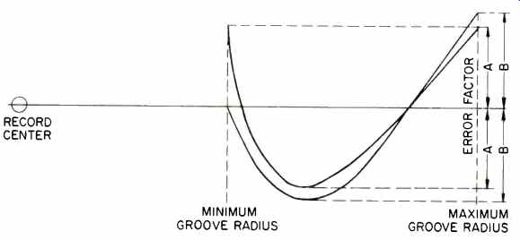
Fig. 3--Error factors for different tonearm layouts.
The minimum modulated groove diameter is not the same on all records, as it depends on the playing time, groove width, etc., and in practice can vary by 2 cm or more on commercial records. Further, although national standards for the minimum permitted groove radius do exist, the various world standards do not specify the same radius. In other words, arms can differ slightly in their geometries simply because the designers have assumed different values for the maximum and minimum limits of groove radii.
Another source of small differences in tonearm geometry can occur because of different design philosophies.
An arm can be designed so that the error factor is equal at the minimum and maximum record diameters, as well as at the point of maximum error somewhere in between, as shown in Fig. 3, Curve A. One could with justification say that since tracking distortion also rises with modulation level, and most recordings have high modulation levels at the end of the record, tracking error at minimum radius should be zero, as shown in Curve B. Small errors in mounting distance from the center of the platter or in overhang adjustment can make comparatively large differences in angular errors, as well as the groove radii at which maximum and minimum errors occur. It is therefore important that the arm support is mounted correctly relative to the turntable spindle and that the effective arm length with the cartridge mounted is correct. This also means that where overhang is adjustable, an arm can be optimized to track any particular record. If the minimum and maximum radii of the modulated grooves on the record being played are measured, optimum overhang can be calculated for the offset angle of the arm, and the necessary adjustment in effective arm length made.
Note, however, that distortion generated by tracking error consists mainly of second and higher order even harmonics, which are the least objectionable of the various types of distortion. Also, tracking error distortion increases and decreases smoothly across the record surface, and no sudden changes occur to make the distortion more obvious. Thus, for any correctly mounted rational design of tonearm, small differences in geometry do not give rise to large audible differences.
Side Thrust or Skating Effect
The expression "skating effect" goes back to the days when a smooth disc was used to demonstrate this effect or to check the compensation applied.
Since this method gives incorrect compensation, the term may also be said to be misleading.
Side thrust occurs due to the offset angle necessary for optimum angular tracking in radial arms. Friction between the stylus and the rotating record pulls the stylus in a direction tangential to the groove, as shown in Fig. 4. Since the force is not in line with the arm bearing, a rotating force is generated forcing the arm towards the center of the record. This force, called side thrust, depends on the instantaneous magnitude of the frictional force between the stylus and the groove walls.

Fig. 5--Analysis of side thrust.
In the absence of side thrust, pressure is equal on both walls of the groove at the points of contact due to the vertical tracking force (VTF), as shown in Fig. 5A. If side thrust acts in conjunction with the VTF, the two forces combine to give a result which is not vertical but is inclined towards the center of the record, as shown in Fig. 5B. The effect of this inclination is that there is more pressure on the inner groove wall (left channel) than on the outer, as shown in Fig. 5C. It is obvious that where this happens the cartridge cannot have ideal working conditions. The effect of side thrust can be compensated by applying a force at the tonearm bearing. If an otherwise correctly mounted and adjusted tonearm distorts due to mistracking on the right channel only on high-level signals, the cause can be inadequate side-thrust compensation; mistracking on the left channel only indicates overcompensation. Side-thrust compensation can be applied in many forms and ideally should give exactly the same force outwards' that side thrust causes inwards. Various methods are used in commercial applications, such as a thread and weight, springs, opposing magnets, etc.
It should be remembered that side thrust is affected not only by relatively constant factors such as the shape and polish on the stylus and by vertical tracking force, but also by the material from which the record is made and by such varying conditions as groove radius and modulation. Since side thrust varies more or less at random over the surface of the record, it can never be compensated exactly. A good compromise is to adjust compensation to cope with the highest level of modulation likely to be met on records. Although overcompensated for all lower levels of modulation, no mistracking will occur at any modulation level because the pressure will always be higher than the minimum required for the stylus to maintain contact with the groove walls.
Tangential Tracking
The conventional tonearm is pivoted on fixed axes to allow movement in the vertical and horizontal planes. Another approach to the design of tone arms is the tangential tracking tone arm.
In the tangential arm the horizontal bearing (which allows tonearm movement in the vertical plane) is a conventional bearing, but the vertical bearing is replaced by a carriage which moves as required to keep the cartridge tangential to the groove, as shown in Fig. 6. Such tonearms are also called parallel or straight-line tracking arms.
The most obvious advantage is that tracking error can theoretically be zero, and the cartridge is allowed to track the record with geometry identical to that when it was cut. In practice this advantage is less important than it might seem, as the errors in correctly designed and mounted radial tonearms are so small that a tangential tonearm provides only minor audible improvement. Also, small tolerance errors in mounting a tangential tonearm can lead to a constant tracking angle error over the whole of the record surface, virtually negating its advantages (a 1-mm error in length gives approximately a 1-degree error at minimum radius).
Assuming that the moving carriage functions ideally, the tangential arm offers two major advantages. Since the minimum length required by radial arms for adequate tracking becomes unnecessary, the tangential arm can be short and straight. The short arm weighs very little and leads to a fairly large reduction in the effective mass of the tonearm. Further, since the bearings are always directly behind the stylus in line with the cantilever, the frictional force at the stylus is taken up by the bearing. Thus, there is no side thrust under any conditions, and no compensation is necessary. The contact force on both groove walls provided by the VTF is the same over the whole surface of the record, and it does not vary.

Fig. 6--Geometry of tangential tracking tonearm.
Many forms of tangential tracking can be devised, from the purely mechanical to contactless electronic servo systems. While the method used is a matter of engineering application, the requirement for the mechanism remains the same for all kinds of tonearm, i.e. that the mechanism should have no (or as little as possible) influence on the function of the cartridge.
Bearings
The primary requirement for the bearings is that they be free from friction, a force that always opposes motion. As the stylus tracks and the arm is moved inwards in a slow spiral by the groove acting on the stylus tip, friction in the vertical bearing (allowing horizontal tonearm movement) exerts a force attempting to stop the arm from moving. The outer wall of the groove must therefore exert a larger force to move the arm, resulting in a higher pressure on the outer groove wall (right channel) with a corresponding decrease on the inner wall. If a correctly mounted and adjusted tonearm mistracks on the left channel only on high-level signals, the cause can be friction in the vertical bearing.
If a record is eccentric, there will also be an outward motion of the tonearm for every half-rotation (if the eccentricity is very small, it may just compensate for the inward motion of the groove at that point with no net outward movement). On the other half-rotation the inward motion will be larger by the amount of eccentricity. Bearing friction will have the same effect, but the increase and decrease in contact pressure will alternate between groove walls.
Friction in the horizontal bearing (vertical movements) has a similar effect when tracking a warped record. In this case, however, the arm is stopped from moving with the warp, resulting in an increase or decrease in the effective VTF on both groove walls simultaneously, depending on whether the stylus is being forced up or down by the warp. The effect will also occur when the stylus is lowered onto the surface to play a record, with a consequent decrease in the effective VTF. Undesirable effects also occur if there is play in the bearings. Such effects do not lend themselves to easy mathematical analysis, because they depend on the complex interplay between the design of the remainder of the tonearm and the amount and type of play. It can be seen that under the influence of external forces (such as friction) between the stylus and the groove, the whole arm will move. If the movement is in the line of the arm tube, it will result in wow, similar to warp wow explained below. But movement can also be sideways or up and down, with results which will depend on a combination of many factors. All that can be said in general is that the result will not be an accurate reproduction of the recorded signal, and the effect is likely to be unpleasant.

Fig. 7--Effect of different bearing heights on stylus movement with record
warp.
Two bearing types require a little elaboration. The first of these is called a knife edge, sometimes used for the horizontal bearing. The entire weight of the tonearm rests on the bearing "edge," which is supported in a suitably shaped slot. In bearings of this type, there is theoretically no friction; vertical movement of the tonearm results in one of the surfaces rolling on the other, rather than sliding. The rolling action will alter the effective length by a small amount as the end of the tonearm rises, but this can be used to advantage to compensate for warp wow. The other type of bearing is the unipivot, in which a single point, on which the arm rests, is used for both vertical and horizontal movements.
While the complexities of the design are a subject in itself and cannot be discussed here, a correctly designed unipivot can provide extremely low friction with minimal side effects.
Finally, an important aspect of bearing design is a consideration of the lead wires from the cartridge. These have to pass through or around the vertical bearing, and they are attached to a point below the surface of the turntable base. As the tonearm moves horizontally, the lead wires twist and may generate torque to move the tonearm either inwards or outwards.
Both the leads and their layout can therefore play an important part in overall performance and may even be a determining factor in the choice of the type of bearing used.
Warp Wow
The height of the horizontal bearing above the record surface is important for reproduction quality. As the tone arm moves up and down under the influence of record warps, the stylus moves in an arc with the axis of the horizontal bearing as its center. If the bearing is well above the record surface, as in the exaggerated sketch of Fig. 7A, the stylus will move forward simultaneously with its upward movement, and the speed of the record groove relative to the stylus will decrease. The effect is identical to a decrease in turntable speed, and it lowers the pitch of the reproduced signal. The reverse occurs as the stylus moves down the warp and the pitch returns to its nominal value. This variation in pitch due to the combination of bearing height and warped records is known as warp wow.
The ideal bearing position is at a height above the record surface equal to the height of warps, which results in minimum changes in relative speed, as shown in Fig. 7B.

Fig. 8--Effect of undesired axis in the horizontal bearing on tonearm movement
with warps.
The axis of the horizontal bearing can lead to another undesired effect unless it is perpendicular to the axis of the cartridge cantilever. As the tone arm moves up under the action of warps, the arm "twists" simultaneously with respect to the record surface, as shown in Fig. 8A. The result is a changing crosstalk pattern as the arm moves up and down, depending on the angle between the transducer elements and the record surface, and this leads to an unsteady or unstable stereo image. In an ideal case the horizontal bearing will be perpendicular to the axis of the cantilever so that the cartridge does not twist, as shown in Fig. 8B.
( Audio magazine, June 1980)
Also see: