
by Daniel Sweeney and Steve Mantz
Approximately 20 years have passed since the solid state amplifier gained ascendancy in the United States. Whatever our current preoccupation with digital audio, and our tendency to see the advent of the Compact Disc as the crucial event in audio history, the mass-market penetration of solid-state amps was a much more important development in the audio industry. Solid-state power brought serious component audio to the masses, brought the Japanese electronics industry to world dominance and had countless ramifications in home entertainment and popular culture.
Because the introduction of solid-state domestic amps in the early 60s produced so many side effects in the audio industry the, manner in which they developed purely as equipment for replicating audio frequency waveforms has become obscured. Most of us recognize that present-day solid-state amplifiers are somehow different in their circuitry from the amps of 20, 15, or even 10 years ago, but how many of us know what changes have occurred, or why, or how? "Plug it in and forget it" is the slogan of solid-state designers--and we do. The amp sits, squat and swarthy on our shelves-untended, undusted, and always adequate to its task.
Articles in some of the smaller audio journals fiercely debate the merits of various arcane circuit topologies, and manufacturers trumpet breakthroughs, but only the most engaged audiophiles follow the murky genesis of the amplifying circuits.
The very obscurity of this genesis can be attributed to the obscurity of amplifier design as it relates to audible performance. While designers themselves endlessly debate the consequences of employing a given circuit topology, a number of reviewers take the attitude that one circuit is very like another since most solid-state amps, old and new, have distortion ratings of a fraction of a percent. And yet the solid-state amp of today is no closer to its ancestors of 20 years ago than man is to Pithecanthropus. Clearly, some thing has been going on inside the chassis during the last two decades.
This article is an attempt to analyze the tendencies that caused solid-state amplifiers to evolve and, we daresay, to improve.
First Glimmerings
After a long incubation in the 1950s, solid-state amplifiers emerged in the early '60s in very serviceable form.
They immediately challenged or surpassed vacuum-tube amplifiers in a number of performance parameters.
The initial advantage that early solid-state amps evinced over their tube rivals was in price. Expensive when first introduced, the silicon transistor soon dropped far below the cost of the vacuum tube, and the new solid-state amps posed an immediate threat to the supremacy of the vacuum-tube de signs in the mass market.
The second achievement of early solid-state design-and the one that chiefly concerns us here-was the low measured distortion of transistor amplifiers. Even in the mid-'60s, transistor amps rivaled tube amps in tests of static distortion. Although tube die-hards insisted that transistor amps were audibly inferior, no one at that time could marshal a persuasive argument as to why this might be so. The digital analog debates in this decade are reminiscent of the controversy surrounding the rise of solid state, but the course the earlier controversy took was different: Vacuum-tube amplifiers were rather quickly dismissed by virtually the entire consumer electronics press.
(The advocacy of tubes by the little magazines was still far in the future.) Thus, tubes lacked a forum.
The one indisputable advantage held by tubes over transistors in the late '60s was sheer power. In that era, no solid-state amp could come close to challenging McIntosh's 350-watt monos, though the market for these behemoths was limited. However, even before 1970, typical solid-state amps had begun to exceed tube amplifiers' power output norms of 20 to 50 watts. By the early '70s, several solid state amps had been introduced whose rated power level exceeded 200 watts per channel with a THD of less than 0.1%. By the standards of the time virtual perfection appeared to have been reached, and the evolution of solid-state amps should have topped about 1972. But it didn't.
Why not? Largely because of the attitudes of the designers themselves.
Whereas some equipment reviewers, at least in the United States, have taken the position that amplifiers of equivalent power ratings are sonically equivalent, the people who actually design amplifiers are more apt to think that these components are sonically distinct. The significant designers of the late '60s and early '70s were unhappy with existing designs on both theoretical and experiential grounds. In spite of the insistence of some reviewers that perfection had been achieved, the topologies of the mid-'60s kept being developed, and amplifiers underwent a continuous evolution that goes on to this day.
The typical transistor amp of the mid-'60s, the first generation, as it were, was what engineers call a quasi-complementary design with single-ended input and driver stages (Fig. 1).
Most of these units, of which the English Leak Stereo 30 is an example, had four stages. The first two stages provided heavy voltage gain, the third stage split the signal into a pair of out-of-phase complements, and the final stage provided current gain. These amps used a single PNP transistor at the input, an NPN in the second (or driver) stage, an NPN and a PNP in the phase splitter, and two NPNs in the output stage. The output transistors were operated out of phase with one another, in a configuration known as a "totem-pole" or quasi-complementary output. A single positive power supply was provided, and the negative rail of the amplifier was at ground-0 V. The power supply was essentially unregulated. However, the Class-A driver had its collector tied to the positive rail via a bootstrap network which simulated a constant current source. A capacitor coupled the output stage to the speaker load and prevented d.c. from the power supply from reaching the speakers' voice-coifs.
Crude though they were, these first-generation amplifier circuits could provide extremely low THD readings, though in the mid-'60s, designers were not yet aiming for the 0.01% distortion figures sought a few years later. At the time, the low distortion ratings attain able in solid-state circuits were often incorrectly ascribed to the purported linearity of the devices themselves.
(Similar false claims are made today for the relatively nonlinear power MOS FET.) In actuality, the low distortion figures were due to the fact that more overall feedback could be employed in a transistor amp than in a conventional tube amp, where phase shifts engendered by the output transformer tend to cause oscillation problems if feed back values exceed about 30 dB.
Despite their low THD readings, these first-generation designs were perceived as problematic by some engineers. The single-ended, single-transistor input stage did not lend itself to direct coupling, and the totem pole had a tendency to "latch up" or stick to the negative half of the wave cycle at high frequencies. Defenders of the to tem-pole output claimed that the high-frequency distortions were inaudible, but others maintained that such distortions could intermodulate and produce beat frequencies in the audible range.
Clever design work ameliorated some of the problems of the quasi-complementary output. Indeed, such schemes are still advocated by high-end designers John Bedini and Bascom King, but most designers eagerly embraced PNP silicon power transistors when they became available at the turn of the decade. Dan Meyer, Dawson Hadley, and John Curl began to experiment with dual differential input stages as early as 1968. Around the same time, John Iverson built fully complementary amplifiers using PNPs in every gain stage.
For several years, however, the power PNP remained in the laboratory. The first PNPs were substantially slower than their NPN complements and had intrinsic distortion levels up to three times higher. They weren't very well-matched devices, and the designers who used them were apt to create more problems than they solved. The second generation of solid-state amplifiers would remain single ended.
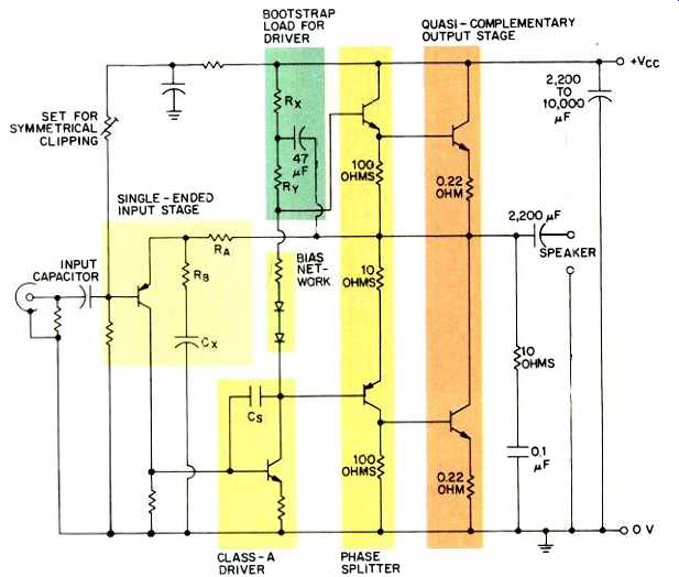
Fig. 1--The first generation of transistor amplifiers, which existed during
the mid-'60s, used quasi-complementary designs with single-ended input and
driver stages. Most had four stages; the first two provided heavy voltage
gain, the next was a phase splitter, and the last provided current gain.
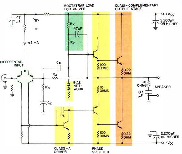
Fig. 2--The basic topology of second-generation amps, which appeared during
the early '70s, included single differential input, constant-current sourced
driver, a phase splitter, and quasi-complementary output.
The Muscle Era
During the second generation of sol id-state design, which began around 1969 and extended through the early '70s, two major advances occurred which led to the general acceptance of transistors in the high end as well as in the mass market. These advances really brought solid-state amplification out of the experimental era.
The first advance was the development of high-power output transistors (all NPN devices, initially). Beginning with the 150-watt/channel Crown Mod el DC 150 in 1967, a rapid escalation in solid-state power ratings began, culminating in Bob Carver's 350-watt/channel Phase Linear Model 700 in 1971. Marantz, McIntosh, CM Labs, Dynaco, and Kenwood all joined in the power race. And though many of these amps were rather optimistically rated by current FTC standards, they definitely settled audio enthusiasts' questions concerning solid state's power potential.
The second advance, less heralded at the time, was the incorporation of differential inputs in high-performance power amplifiers. A differential (or difference) amplifier is a circuit that amplifies a signal equal to the difference in voltage potential between the positive and negative inputs in a balanced input configuration. Differential amplifiers had been used in tube circuits since the '30s, but they especially recommended themselves to solid-state designers by virtue of their thermal stability. Differential front-ends are practically universal in solid-state amplifiers today-a design cliché, so to speak. In the late '60s, however, they represented a startling innovation.
Yet another circuit refinement made in the '70s was the current mirror. It forms an active load on a differential front-end. The current mirror extracts the differential output from the differential pair and converts it to a single output referenced to ground. The circuit doubles the gain-bandwidth product of the amplifier compared to a constant-current active load. The provision of extra gain permits the designer to apply more feedback. The current mirror was extremely popular with Japanese designers of the '70s and early '80s, most of whom favored high feedback to achieve low static distortion; the circuit has found less acceptance among high-end designers in America and Europe. Among the relatively few non-Asian manufacturers which have used current mirrors are Mark Levinson, Apt, and Electrocompaniet.
Among the other refinements in the second generation was the split power supply-in effect, two supplies (one positive and one negative). The split supply provided d.c. stability and, consequently, a measure of loudspeaker protection. It also permitted the de signer to dispense with the output capacitor, to the supposed sonic benefit of the amplifier. There was, however, one potential difficulty with the split supply; it increased the potential for harmful d.c. in the speaker if an output device shorted. The coupling capacitor in the earlier designs actually would not let the d.c. get through to the speaker.
The final major refinement was the provision of a constant current source for the driver stage. As the name implies, it insured that the driver operated under conditions of constant electrical current flow from the power supply.
This allowed the driver to swing voltages independently of power-supply fluctuations.
A basic topology of single differential input, constant-current sourced driver, phase splitter, and quasi-complementary output characterized most of the high-powered amps of the early '70s (Fig. 2), and such circuits would be widely employed until the end of the decade. These high-powered, second generation amps were ubiquitous in the better music systems of the early and mid-'70s, and they yielded impressive results driving the inefficient acoustic suspension speakers favored by audiophiles at the time.
Designers still were not satisfied.
The tube camp-what was left of it still insisted that transistor amps sounded harsh. Many solid-state audio engineers privately agreed and felt that a fundamental redesign of power amplifier circuitry was in order.
The Classic Era
Solid-state amplifier design came of age in the mid-'70s. Amplifiers from that era were the first transistorized components to attain the status of classics-that is, components with stable and enduring monetary value.
Jim Bongiorno's trend-setting Ampzilla from GAS was one of the first of these classics, and it possibly had the greatest influence on other amplifier designs of the period. Because this article is not a subjective report, we offer no opinions as to this amplifier's sonic attributes, but Ampzilla was widely regarded as the best-sounding solid-state amplifier of its day. Its introduction brought into focus discussions of supposed sonic differences among amps, discussions that had generally lapsed during the eclipse of the vacuum tube and the early solid-state power race. Bongiorno himself maintained that Ampzilla surpassed the competition sonically, and he credited the amplifier's sound to its then unusual circuitry.
That circuitry (Fig. 3) bears examining. At input, Ampzilla employed a matched complementary differential pair, a circuit pioneered by Dan Meyer of Southwest Technical Products (but which was very rare in a commercial product). The driver stage was also complementary, and each driver formed the load for the other. The power supply itself was split, and it featured a total of over 32,000 uF of capacitance, a very large value for the period. The power transformer was also massive and utilized square wire in a proprietary design. High current had not become a buzzword (and wouldn't be for at least another eight years), but Ampzilla provided it-and with pretty good regulation, to boot.
Naturally, the outputs were truly complementary, not quasi, and the output transistors were connected in series rather than in parallel (the universal practice at the time). Such series connections vastly reduced the voltage swing over which the output transistors operated, which in turn increased their safe operating area. Series connection had been used much earlier in the germanium transistor amps of the early '60s, but Bongiorno brought the practice into prominence. Series-connected outputs subsequently appeared in Nelson Pass' famous Threshold amps, among others.
Today, fully complementary design is commonly used in esoteric amplifiers made in the United States. (It is a rarity in Japanese amps.) However, the series output pioneered by Bongiorno has passed into disuse due to the availability of power transistors with higher voltage capabilities than those used a decade ago. Other aspects of the Ampzilla circuit continue to appear in contemporary designs. Ampzilla was one of the earliest designs with low global feedback. It achieved low distortion through complementary circuitry and by using local feedback loops around individual gain stages, a tactic used widely in present-day circuits and exemplified by the amplifiers of Threshold, Rowland Research, SpectraScan, and B & K among others. Copious use of local feedback combined with low values of global feedback (under 35 dB) is becoming increasingly characteristic of American esoteric and high-end design. Indeed, low or zero global feedback has be come almost a matter of dogma among American high-end audiophiles and designers.
When Ampzilla appeared, the critique of global feedback was just be ginning to penetrate the engineering fraternity, but it quickly gathered force in the second half of the decade and ignited a controversy that continues to this day. Not unexpectedly, the critique of feedback has had a profound effect on both the design and marketing of solid-state amplifiers. It has become as much a matter of ideology as of engineering.
The technical arguments for low values of global feedback are too involved to review in detail here, but they rest principally on two observations.
First, global feedback reduces total harmonic distortion but increases the relative weight of irritating high-order distortions. Second, global feedback is ineffective in correcting for certain types of transient distortion, A more recent argument is based on the observation that amplifiers become effectively open loop under certain load conditions, and that amplifiers de pending entirely on global feedback to control distortion will function poorly under such conditions.
The ideological arguments are harder to summarize, compounded as they are by subjective impressions and technical half-truths. Some of the objections advanced have dealt with the supposed relationship between negative feedback and slew rate limiting in an amplifier (see sidebar on TIM), and the purported ineffectiveness of feed back since it is applied "after the fact." All of these arguments, technical and ideological, won adherents in the esoteric wing of amplifier design in the United States, Europe, and Japan, and were repeated by hobbyists patronizing such manufacturers. Audio equipment reviewers, for the most part, discounted such arguments. They assumed the position that massive amounts of global feedback were an entirely respectable way of lowering distortion, and that the distortion figures themselves were all that mattered, not how the designer achieved them.
======================
Understanding TIM
Transient intermodulation distortion (TIM) is a type of voltage clipping. It occurs when an amplifier is forced to accept a sufficiently rapid change in input voltage within its initial gain stage that the gain devices cannot accurately pass the wave forms (that is, when the amplifier's slew rate is exceeded). TIM is directly related to the full-power bandwidth of an amplifier. An amplifier that can produce full power at 200 or 500 kHz has a very high slew rate and will be little subject to TIM.
Matti Otala, now a very prominent Finnish engineer, coined the term in 1975. He suggested that TIM resulted in audible differences between amps of equally good performance on static distortion tests. His ideas found ready acceptance among those in the audio community who believed that solid-state amps ready did differ sonically. (Around the same time, engineers from an opposing school of thought were publishing results of blind listening tests Their tests purported to show that most solid-state amps were in distinguishable from one another at any level below clipping.) Manufacturers themselves were much exercised by Ota la's concepts, and amplifier slew rates increased by multiples.
From the perspective of the present, the whole issue appears passé. In 1975, many solid-state amps had slew rates in the 5-V/uS range-low enough to invite overload by moving-coil cartridges playing very dynamic material. Today, no high-end amp worthy of the name claims a slew rate of less than 20 V/uS--at least, no solid-state amp. In any case, no one standard procedure for measuring TIM has ever been accepted as necessary by the industry at large.
======================
In fact, massive global feedback is an easy way of getting low percent ages of distortion. Although amplifier stability may be sacrificed in the pro cess, you don't have to use precisely matched components, you don't have to resort to expensive and inefficient Class-A operation, and you don't need high-quality power supplies. All you need is high gain, and that's easy to achieve with present-day semiconductors. Indeed, most mass-produced power amps today, especially those found in receivers and integrated amps, use very high values of feed back to get the 0.005% THD readings typical of the industry.
In some respects, the continuing prevalence of massive global feed back is remarkable, since, as we will demonstrate in a moment, esoteric de signs have, since the mid-'70s, tended to determine the form that mass-market designs take. Yet in this matter of negative feedback, the mass-market designers have persistently opted for high values. The ubiquitous THD specification is one that is perceived as important by multitudes of buyers, and there is no cheap way to manufacture an amp with very low THD without lots of global feedback. It is interesting to note that the cheapest receivers on the market typically boast lower rated THD than the expensive offerings of Mark Levinson. This disparity may be explained by the much greater use of global feedback in these receivers, but from a sales perspective, mass-market manufacturers really have no choice.
Marketing considerations aside, one of the earlier and more prominent critics of global feedback, Nelson Pass, claims to have conducted blind listening tests during the development of his Stasis amplifier circuitry. The tests indicated that zero feedback circuits could be distinguished from those employing global feedback and that they were judged more pleasing. Pass feels that the strongest evidence against the practice of using high values of global feedback can actually be seen in the marketplace itself. "Name an amplifier from the past with extremely low distortion obtained through high values of feedback that is still considered a classic," he argues. (We might add parenthetically that we could not, in fact, think o' any designs with high global feedback going for big money on the used market. One could, however, argue that audiophile collectors have simply been brainwashed by the anti-feedback camp.) At any rate, the course that solid state amplifier design has followed from the early '70s to the present suggests that engineers who've designed no-compromise products have generally not relied on large values of global feedback to linearize their circuits. In stead, they have sought to reduce distortion by other means. Two distortion-reducing techniques have gained especially wide acceptance: Cascoding and Class-A operation.
Of the two, cascoding is much more common (if less publicized) in modern amplifier circuits. A cascode, not to be confused with a cascade, is a pair of devices acting as a single unit. (Tubes can also be cascoded, but that won't concern us here.) The bottom transistor is a common-emitter connection providing voltage and current gain; the top transistor is a common base pro viding high voltage gain. Common emitters are generally used to provide voltage gain in the input and driver circuits of a power amplifier. Transistors operating in the common-emitter mode are subject to the Miller effect, which may be described as a high-frequency roll-off due to collector-base capacitance. The Miller effect is exacerbated when high voltages are impressed across the transistor. The purpose of the top transistor's common-base connection is to shield the common-emitter transistor from high voltages and voltage changes because the common base is inherently a regulator. The cascode provides high gain, high linearity, and broad band width. It is very widely used in contemporary amplifiers.
Cascoding (Fig. 4) first appeared in the early '70s in amps by SAE, CM Labs, Dynaco, Marantz, and, most remarkably, in the output stage of Nelson Pass' first Threshold amplifier. Pass still uses cascode outputs in the Stasis circuits of his current amplifier line.
Cascode outputs also appeared in JVC's discontinued Model ML-10.
Since transistors are especially non-linear when used to provide voltage gain, cascoding in the voltage gain stages must be counted as a major advance. Curiously, the cascode has never captured the attention of the enthusiast buyer, and its increasing use in modern solid-state circuits has passed almost unnoticed. Instead, the attention of the audiophile has focused on the output stage, where Class A-operation began to appear in a number of amps from the early '70s, creating a mystique among the cognoscenti rivaling that of the still fitfully alive vacuum tube.
Class-A operation had been used for decades in low-powered vacuum-tube amplifiers, and it was commonly used in the voltage amplifying stages of solid-state components. But power transistors proved difficult to operate in Class A because of their high susceptibility to thermal runaway, where destructive currents burn out the transistor as rising temperatures make it more conductive.
In true Class-A operation, a gain device will conduct electrical current at all times, from a no-signal condition to full rated output. Bias will therefore be set to about half of peak current, and electrical consumption and heat dissipation will be prodigious. Class-A operation eliminates switching distortion in transistors, and it forces the transistors to function within the most linear portions of their operating region. Furthermore, the transistor is kept quite stable thermally, so its gain characteristics are relatively invariant.
Class-A operation has other characteristics as well. In a complementary Class-A amplifier (virtually the only kind produced today), idling current is about half the peak current into a rated load, so idling power dissipation in the output stage is about twice the avail able maximum output power. The amp, therefore, has a massive power sup ply, with all the advantages that this provides. Many of the most prized sol id-state amps have been full Class A, or close to it, including the Mark Levin son ML-2, the Stax DA-100, the Krells, and the Electro Research 75.
The first Class-A transistor amp that we know of was the little English Sugden, circa 1968, a single-ended de sign producing only about 10 watts per channel. It was followed after a lengthy interval by the Stax DA-300 in the early '70s, the Mark Levinson ML-2 in 1975, and the Electra Research 75 at about the same time. The Levinson unit is still made today, and a handful of other Class-A amps are available from such firms as Threshold, Krell, Luxman, and Audire--all at premium prices. No true Class-A amp has ever been produced for the mass market. The requirements for extremely massive power supplies and extensive heat-sinks and/or fan cooling-as well as the very high ship ping weights of these components necessarily relegate the prices of Class-A amplifiers to the market's extreme high end.
Nevertheless, the mystique of Class A began to reach into the mid-market beginning in the late '70s, creating a demand for a product that simply could not be delivered at a price conducive to mass acceptance. Determining the reasons behind the mystique is difficult, but at least two explanations suggest themselves.
Class-A operation is literally a text book method for reducing distortion, albeit one that is difficult to implement in solid-state amplifiers of more than about 20 watts output. In an engineering sense, Class A is noncontroversial, though it's very debatable from the perspective of price versus performance.
Another factor contributing to the mystique is the ability of most early, true Class-A amps to control certain difficult speakers, notably electrostatics. At the time that the first Class-A amps 'reached the market, electrostatics (such as the Koss Model One, the Beveridge, and the Dayton Wright) were enjoying enormous acclaim.
Class-A amps, with their enormous current capabilities, could handle the low impedances presented by such speakers and make them perform at their best. This fact put Class-A amps in an exclusive category. Because Class-A amps had a way of turning up in the most ambitious music systems, they became the preferred design. But they were still prohibitively expensive.
Enter pseudo-Class A or, if one is more charitable, quasi-Class A. This was another design from the fecund imagination of Nelson Pass, first surfacing in his Cascode amplifier in 1974. A number of variants of pseudo-Class A now exist, but the first and most widely used version consisted of a dynamic biasing circuit-also called a sliding bias-that varied the bias of the output transistors according to the strength of the input signal. On an instantaneous or cycle-by-cycle basis, bias will be very high during strong-signal conditions but will be low at all other times; at no time will the output transistors shut off and generate notch distortion. Unless the amp is run very hard, power consumption and heat dissipation are only slightly greater than in Class-AB designs.
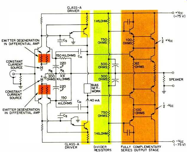
Fig. 3-Great American Sound's Ampzilla was widely regarded as the best-sounding
amp of its day. It used a matched complementary differential pair at the
input, and the driver stage was also a fully complementary series output.
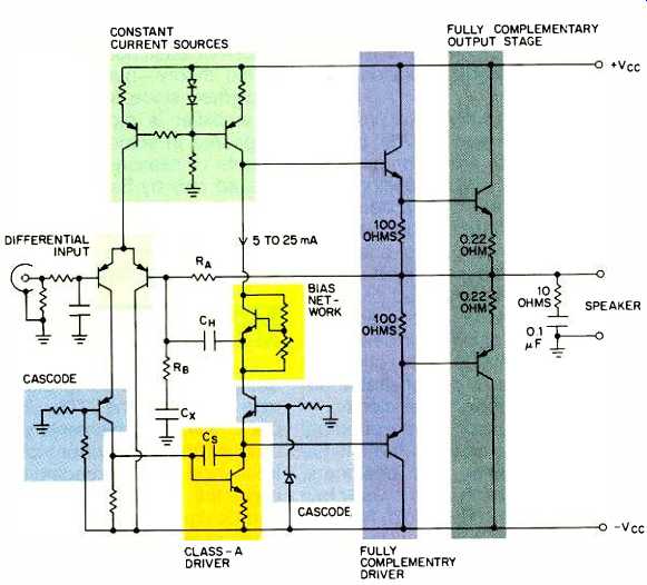
Fig. 4--Cascoding first appeared in the early '70s, and it provided high
gain, high linearity, and broad bandwidth. Used fairly widely by designers,
cascoding should be regarded as an important circuit technique, even though
it has not been faddishly sought after by high-end buyers.
Nelson Pass no longer uses the sliding bias circuit-nor does any high-end American manufacturer. However, this circuit has become almost standard in mass-produced Japanese amplifiers, appearing in units from Pioneer, Technics, Denon, Onkyo, JVC, and Fisher. Whether or not the eclipse of pseudo-Class A in the high end is based on performance factors, we don't pretend to know. Pseudo-Class A does not offer all of the benefits of true Class-A operation: It does not provide the same degree of thermal stability, and it does not linearize transistors to the same degree. Thus, it simply results in more open-loop distortion.
Class-A output operation has remained the perfectionist approach in the United States and Japan, but several other means of linearizing outputs-all of which can be discussed in a few words-have been attempted.
Class-D operation is one such method. Class D is an operational mode where by the audio signal modulates a high-frequency pulse train and varies the duty cycle, or width of the pulses, without affecting their amplitude or frequency (which are held constant). An output filter is used to strip away the carrier frequency and produce an audio frequency output. Class-D amplifiers are sometimes inaccurately termed "digital amplifiers," though the proper term is "pulse-width modulation amplifiers."
Sony and Infinity Systems produced Class-D amps in the late '70s, but neither they nor any other company has been successful with the design in the marketplace. Class-D amplifiers have proven to be far less reliable than conventional audio amplifiers and have demonstrated no superiority in specifications. They also have had problems in driving reactive speaker loads, be cause the speaker load is in series with the output filter and therefore affects its operation. The sole demonstrable ad vantage of the design is efficiency.
The current-dumping type of output circuit has fared better in the estimation of audiophiles and designers.
However, it has been used by only four companies: Quad, Threshold, Nakamichi, and recently Technics. (Nakamichi is licensed by Threshold to use its Stasis circuit.) In all these circuits, voltage gain and current gain are provided at output by separate gain blocks connected to the load in tandem. One block provides current gain, while the other produces voltage gain. The voltage-gain block is operated in Class-A mode; the current-gain block is operated in Class B or AB. Distortion characteristics of these current-dumping circuits are said to be determined by the smaller Class-A circuit, which in effect shapes the output waveform. (Threshold, incidentally, recently introduced a couple of current-dumping amps which operate in Class A in both the voltage-gain block and current-gain block sections. When interviewing Nelson Pass for this article, we asked what the point was of combining Class A and current dumping.
"It provides for superior presentation of depth," he replied.) Related to current dumping is an old technique called feedforward, which was recently resurrected after being developed back in 1927 (by H. S. Black of Bell Labs) and ignored by the audio industry for 50 years. In classical feedforward circuits, a small error-correction amplifier is bridged to the main output and corrects for its nonlinearities by injecting an out-of-phase error signal into the main amplifier's output.
Feedforward does not produce the deleterious effects of negative feed back-at least, not according to established theory-but it is expensive to implement since, in effect, an addition al amplifier is required. Feedforward appeared in some Denon amps for a couple of seasons, but it is currently offered only by Sansui (though Yamaha's Zero Distortion Rule circuit is somewhat related). Basically, feedforward represents a road not taken in solid-state amplification.
The Eighties: Electronic Scholasticism
In one sense, solid-state amplifier design has matured in the '80s. The innovations of the '70s-local feed back, fully complementary circuitry, dual differentials, current mirrors, FET front-ends, and cascoding-have be come the standard ploys of the high-end designer. Low-end manufacturers have ceased to design at all-they simply plug in new power ICs and purchase ready-made circuits from a chip supplier.
Although the topologies of most high-end amps at mid-decade were in common use in 1980, the climate of high-end design is very much different today. The concerns of perfectionist designers have shifted from basic topologies to the arcana of passive components. Fierce debates rage concerning the audible differences between polystyrene and Teflon capacitors, the effects of placing laminated iron cores over power transformers, the improvements to be had by using oxygen-free copper wiring, and even the benefits of using sound-proofing cabinets to prevent microphonics in transistors. (Interestingly, most of these notions originated in the Japanese high end, but the components that the Japanese favor rarely spark much enthusiasm among American high-end designers and consumers.) All of this attention to minutiae would augur that solid-state design has entered a late-Mannerist stage from which little significant innovation is likely to emerge. Indeed, this is our view.
Unless radically new devices (such as the still-experimental gallium-arsenide transistors) find acceptance--or unless truly high-performance, pulse-width modulation Class-D amplifiers are somehow developed-we see little fundamental change for the next few years.
And yet, solid-state amplifiers have changed along some performance parameters, if not in basic design. Ideology, always a potent force in audio electronics, has fastened on a new controversy, and manufacturers and consumers alike have become preoccupied with the matter of current capability.
Matti Otala, who initiated the TIM controversy, was largely responsible for launching the discussion about high current as well. Some years ago, Otala called attention to the fact that crossover-induced impedance nulls in dynamic loudspeakers could present an amplifier with a load of less than 1 ohm, which would in turn place enormous peak-current demands on the amplifier. Subsequently, Otala participated in the design of a very high current amplifier for Harman/Kardon, giving substance to his theories. To be sure, high-current amps were advocated back in the '70s by Bose, Crown, and NAIM Audio, but only in the early '80s did high-current capability become a selling point.
Otala's observations concerning amplifier-speaker interactions were correct and verifiable, though the presence of impedance dips in dynamic loudspeakers causes problems for amplifiers only over a relatively narrow range of frequencies and only at high playback levels. Electrostatic loud speakers, whose impedances fall and become progressively more capacitive as frequency rises, present a much greater challenge to a solid-state amp's current capabilities than do the ordinary cones and domes of dynamic loudspeakers. The relatively few audiophiles who own such speakers have insisted on amps with massive current capabilities all along. The recently introduced wide-range ribbon speakers (made by such manufacturers as Apo gee and VMPS), with average impedances of under 4 ohms, present similarly difficult loads to amplifiers.
The controversy surrounding high-current capability extends considerably beyond the owners of such esoter ica as ribbons and electrostats. High current has acquired its own mystique (just as did Class A), and high-current amps are said by their defenders to sound more "open." High current has come to be regarded as a desirable attribute in an amplifier and not just as a means of coping with certain difficult speaker loads.
The advocacy of high current has an interesting corollary. Current limiters, used to restrict current flow and protect output transistors, have come to be seen as sonically undesirable in the high end. Many purists insist that power amps should be run with no protection other than that provided by over rated output transistors and, perhaps, a fast fuse. Accordingly, many American high-end amplifiers have no current-limiting protection of any kind. Curiously, this particular design trend has gained no acceptance in Japan, where designers (esoteric and otherwise) are united in their insistence that products should be foolproof.
Nevertheless, the Japanese have somewhat belatedly embraced high current, as it has become a general obsession in the audio community. To day several mass-market amplifiers from the Orient are selling components on the basis of their supposed high-current capabilities.
So what consequences has this quest for high current had on design? Primarily, it has popularized modulated power supplies. Classical amplifier de sign theory posits a ripple-free, low-impedance power supply that holds supply-rail voltages steady under all normal load conditions. Amplifiers following this theory have utilized large transformers and filter capacitors, and occasionally have used voltage regulators. They have also been characteristically expensive.
To achieve acceptable sound quality, such "brute-force" power supplies are an absolute necessity when operating a solid-state power amp into a broadband 2- or 3-ohm speaker. For loudspeakers where the load only dips to low impedances at certain frequencies, one can generally get by with an amplifier whose power supply will momentarily dump large amounts of current into a load. This instantaneous current capability can be achieved in a number of ways: By varying the voltage rails on the supply and allowing the power transformer to "load down" (a la Carver or Soundcraftsmen), by stacking dual supplies (in the manner of the NAD 2200), or by simply loading down a small transformer and letting the supply rails sag (as in the Apt power amp). Many designers maintain that such tactics seriously compromise sound quality. Certainly they go against classical principles of good power-supply engineering, but amplifiers employing such modulated power supplies generally perform quite acceptably on static distortion tests.
One must be cautious in predicting the future of solid-state amplification.
After all, in 1970, few thought that vacuum-tube products would enjoy a strong specialty market 15 years later.
We see several areas where research is likely to focus: Fully regulated power supplies, switching power supplies, Class-D operation, power ICs, and new types of transistors. In mass-produced amplifiers, ICs will almost completely replace discrete circuitry in five years; in cheap, high-feedback integrated designs, we see the addition of second-harmonic distortion generators (of the Aphex Aural Exciter variety) possibly being added to sweeten tone.
Class-D amplifiers will certainly reap pear in improved form, but will only succeed in high-power applications.
And five and even 10 years from now, vacuum-tube amps will still be manufactured, cherished by a small contingent of loyalists.
==================
FETs and MOS-FETs
Oskar Heil, an Austrian physicist who later gained considerable fame in audio circles for his air-motion transformer loud speaker, developed a field-effect transistor in 1933-some 15 years before Bell Labs devised the bipolar. Heil did nothing with his invention, and field-effect transistors (FETs) were not seen again until the 1960s (and then, only in laboratories). It wasn't until the mid-'70s that FETs appeared in consumer audio products.
The major Japanese manufacturers pioneered the use of FETs in amplifier circuits. The first application was in the differential input stages of power amplifiers, and, indeed, such FET differentials have come to typify Japanese amplifier design.
FET front-ends did not arouse much comment when they first appeared. In the late '70s, however, FETs came very much to the fore when the first amplifiers with FET outputs were introduced by Sony and Yamaha in Japan, by Peter Perreaux in New Zealand, and by Spectral Audio in the U.S. The Sony and Yamaha amps used power V-FETs; the other two employed the new metal-oxide semiconductor FETs (MOS-FETs). Today, the MOS-FET is the only FET in use in power output stages.
MOS-FET outputs recommended themselves for two significant reasons. First, MOS-FETs are high-impedance devices that require negligible current at input.
Like vacuum tubes, FETs swing current as a function of input voltage (in contrast to bipolars, which swing current as a function of input current level). Second, FETs are square law devices in terms of their gain characteristics, and they tend to share the desirable distortion spectra of vacuum tubes. Audiophiles have been especially taken with the second attribute, and like to speculate on how the tube-like characteristics of MOS-FETs would lead to the marriage of tube amplifiers' sweetness and solid-state amplifiers' reliability.
Nevertheless, MOS-FETs have not come close to replacing bipolar transistors as output devices. Many high-end designers feel that MOS-FETs are highly problematic because of high gate capacitance, high intrinsic distortion,' and in creasing internal impedance with rising temperatures.
In mass-market integrated amplifiers and receivers, MOS-FETs are seldom used in output stages-nor are they likely to be. Because of their distortion characteristics, MOS-FETs are generally biased hard, to bring distortion down. Consequently, MOS-FET amps run hot. Heat is unacceptable in a mass-market design (particularly in one with an IC output stage), so MOS-FET amps are apt to re main in the high end.
(adapted from Audio magazine, Jun. 1988)
Also see: Simple Construction Projects--Build an Active Filter (July. 1988)
Cable and the Amp / Speaker Interface (Aug. 1989)
= = = =