by Kenneth L. Kantor
[Kenneth L. Kantor is Director of the Advanced Development and Research Division of Teledyne Acoustic Research in Canton, Mass. ]
The new MGC-1 speaker from Acoustic Research is based on a body of psychoacoustic data which is well documented but little known, rather than on rabbit-from-the-hat trickery.
The design uses side-firing drivers, which are fed a delayed and contoured signal, to establish a firmly fixed soundstage that is both wider and deeper than the space in your listening room.
With science marching on and all that, the sonic differences between brands of a given hi-fi component are often reduced to subtleties. Loudspeakers, however, are the notable exception; they remain an enigma. Maybe that's what makes them so much fun. There are roughly 1,500 home loudspeaker models on the U.S. market. Each model has, by and large, its own distinct sonic character. Why so many different sounds? Some certain response must be correct; why can't loudspeaker designers consistently approach it? Consider, for a moment, the typical audiophile venturing to the local high-end shop to audition amplifiers. For this purpose, he requests a pair of the most "revealing" speakers available. These are graciously provided. As our friend struggles to hear the audible implications of the sub-subsonic filter versus the damping factor of 10,000, he moves his head-not much, just a few inches here and there. Each time he moves his head, the response he hears from the speakers, as measured by conventional methods, is changing by more than a few dB. He never even notices-and he is a very fussy listener. Actually, he so likes the loudspeakers that he pronounces them to be beyond "revealing"; he pronounces them positively "merciless." Clearly, conventional frequency-response measurements are not sufficient to quantify loudspeaker performance in a meaningful way. In fact, the measurement techniques most often used to test speakers are engineering conveniences only. They do not take into account the characteristics of the human hearing system and so do not always relate very well to listening tests.
The other thing they don't take into account is music.
Where and how music is recorded profoundly affects the requirements for accurate reproduction. It is too simplistic to say that accuracy is absolute. Stereo recordings contain precious little information about how spatial characteristics should be reproduced. Both practically and mathematically, two electrical voltage signals cannot fully define the sound field in a listening room. It is unfortunate but true: Every loudspeaker is more than a reproducer, it is an interpreter. These are not just engineering problems. They cannot be solved by designing better drivers or using different speaker cable. The answers lie in understanding human hearing in relation to sound reproduction. How do we perceive the location of a sound source? What actually causes tonal coloration? What makes a room sound large or small? And the bottom line: How do all of these considerations relate to loudspeaker design?

Fig. 1--Time response to a 10-uS pulse of a conventional speaker system in
a typical listening room, with microphone at listening position. (All vertical
amplitude scales are linear except where otherwise noted.)

Fig. 2--Time response of an ideal speaker to a 10µS pulse in a nonreflective
room.

Fig. 3--Same as Fig. 1, with time scale lengthened to 20 mS to show room-boundary
reflections.

Fig. 4--Same as Fig. 3, with time scale lengthened to 40 mS.
Psychoacoustics Background
In essence, psychoacoustics is the science that relates the properties of sound sources and listening environments to our perceptions of them.
Modern psychoacoustics was born in the middle of the 19th century with the publication of the classic book On the Sensations of Tone, by the German physicist Hermann von Helmholtz [1]. That von Helmholtz could learn as much as he did, using the primitive mechanical means available to him, is remarkable. It wasn't until electronic signal generation and measurement became possible that the science of psychoacoustics really took off, fueled by the advent of telephony. While cur understanding of human hearing is far from complete, there is psychoacoustics work covering most aspects of sound perception. Buried in 100 years of research are a number of studies very relevant to loudspeaker design and measurement.
Psychoacousticians have determined that the ear is sensitive to more than just the frequency content of sound signals; temporal and spatial properties also affect perception. For amplifiers and the like, this presents no problem; the time distortions caused by electronic devices are minute compared to the ear's sensitivity, and these devices are irrelevant to the spatial characteristics of the reproduction system. Loudspeakers, however, have very complex temporal and spatial responses. Whenever a loudspeaker is used to reproduce sound, the audio signal undergoes spectral, temporal and spatial distortions which profoundly affect our perceptions. By understanding the nature of these distortions, we can reduce their influences and even exploit them to improve perceived reproduction accuracy.
It is well-known that when a speaker is used in a listening room, only a portion of the sound reaches the listener's ears directly from the drivers. Some of the energy is reflected by the speaker cabinet itself-off of grille frames, trim rings, and cabinet edges. Some of the sound bounces once or twice off the room boundaries before reaching the ear; some bounces around the room for quite a while before being absorbed. The longer the reflected path, the later the sound arrives.
The characteristics of the first-arrival signal dominate our perception of the location and timbre of sound sources.
To determine the influence that a given echo will have on this perception, it is necessary to know its amplitude, its spectrum, its delay time and the direction from which it arrives. With this in mind, let's examine the behavior of real loudspeakers in home listening rooms.
Figure 1 shows the time response of a conventional loudspeaker to a single, 10-uS pulse; the horizontal scale totals 4 mS, with each division being 200 µS. The measurement was made in a typical listening room, with the microphone at the listening position. If the reproduction from the speaker were perfect, and the room added no reflections, this response would look like the ideal shown in Fig. 2.
There are three predominant reasons why the response is distorted.
First is the dispersive nature of the system. In other words, signals of different frequencies reach the listener at different times. Since the pulse contains many frequency components, these time delays change its shape.
Dispersion is due to the physical separation of drivers covering different frequency ranges, to electrical phase shifts in the crossover networks, and to mechanical phase shifts in the drivers.
The subject of loudspeaker dispersion was first examined in detail by Richard C. Heyser [2], who went on to develop useful mathematical and measurement tools to study it. Prior to Heyser, most speaker designers used frequency response alone as a quality index.
Heyser's work was not in psycho acoustics per se, as it dealt little with human perception. However, it did establish an important link between loudspeaker engineering and the large body of psychoacoustics dealing with temporal aspects of sound perception.
The second type of pulse distortion seen is the occurrence of delayed and attenuated repetitions of the initial pulse, caused by reflection and diffraction from cabinet elements. In this example, these occur for about 400 µS after the initial pulse, corresponding to delay paths of about 14 cm. The third type of distortion present is floor reflection, seen at about 2 mS after the initial pulse.
Some of the ways in which the signal in Fig. 1 deviates from the ideal can lead to both tonal and localization errors in the perceived sound. The audible effects of signal dispersion have been the subject of much investigation and heated debate. Blauert and Laws [3], and others, have concluded that phase shifts can affect the timbre of special test signals, but only when the delay times are much longer than typically found in home loudspeakers.
Most researchers agree that phase delays of less than about 1 mS will not cause tonal coloration in a loudspeaker. However, their effect on localization is less well-understood. It is known that if the phase shifts between two stereo loudspeakers differ even slightly, imaging can suffer. The effects of consistent phase shifts on imaging are unknown; every speaker designer has an opinion on the matter. Improving loudspeaker performance in other ways tends to reduce phase shifts, anyway.
The effects that very early reflections have on localization have been studied by many researchers. Blauert [4] found that reflections up to about 600 µS can distort transient localization. Kates [5] examined the problem of very early reflections caused by loudspeaker cabinets and found that, in addition to tonal coloration, they cause image blurring and ambiguity. It is clear that for best imaging, and for minimum tonal coloration, early cabinet reflections should be minimized.
As we begin to examine reflections with longer delay intervals, we find that their effect on localization diminishes.
Tonal coloration becomes the major problem until times beyond roughly 20 mS are reached, when reflections begin to affect perceived ambience. The degree to which reflections of different time delays distort the perceived spectrum has been measured by Atal, Schroeder, and Kuttruff [6]. Their results agree well with studies of loudspeaker reflections done by both Kates [7] and Salmi and Weckstrdm [8]. All indicate that reflections occurring at about 2 mS are the worst offenders. From this we can infer that the floor reflection seen in Fig. 1 will cause tonal coloration to an extent underestimated by conventional measurement techniques, a conclusion reached also by Kates. The floor reflection can also stretch the sonic image in the vertical plane when the speakers are reproducing sustained tones.
Figure 3 shows the same signal as Fig. 1, displayed over a longer time scale. The horizontal axis is now 20 mS; each division is 1 mS. Reflections from the various room boundaries are clearly visible. These reflections cause significant spectral coloration and some imaging errors. By noting at what point in time a reflection occurred, it is possible to calculate how far the reflected sound travelled, compared to the direct sound, before reaching the listener. To do this, multiply the echo delay time (in milliseconds) by 1.1 to get feet. For example, a reflection off a wall located 2 feet behind a speaker would have to travel about 4 feet farther than the direct sound before being heard. This reflection would therefore reach the listener about 3.6 mS after the direct sound (4 divided by 1.1 equals 3.64). Figure 4 shows the response of the speaker over 40 mS; each division is 2 mS. Only a few distinct reflections emerge from the background reverberation after 20 mS. While the reproduction of certain types of music might benefit from the presence of some reflections later than 20 mS, the early reflections we see from the loudspeaker cabinet and listening room distort both localization and perceived spectrum. To assure the greatest reproduction accuracy, it is desirable to have as little reflected energy as possible reach the listener for the first 20 mS after the first arrival. Beyond this time, the effect of reflections on localization is minimal, and their effect on timbre is largely diminished.
In a given room, the density of early reflections is a function of loudspeaker directivity [9]. The more directional the radiation, the less the excitation of the room. This suggests that a more directional loudspeaker will be less subject to room-induced colorations. If the radiation could be accurately aimed toward the listener, an additional benefit would be realized: The listener would be assured of receiving the greatest proportion of the radiated energy directly, thus increasing the ratio of direct to reflected sound and further reducing colorations. Additionally, if it were possible to position directional speakers such that each ear was relatively well-isolated from the opposite speaker, it would lead to better stereo separation and a broader soundstage.
It is not possible to determine a single, ideal response for a loudspeaker's long-term reflection pattern. For some program material, reproduction would be most accurate if the speaker/room combination added no reflections at all. This "headphone" type of reproduction might be appropriate for binaural recordings and for synthetic studio material. On the other hand, accurate reproduction of "live" recordings is known to be improved by the presence of significant room reflections well beyond 20 mS. This seems to be the case even if there are such reflections contained in the recording, due to the fact that recorded reflections arrive at the listener coincident with the direct sound and so provide no spatial cues.
Barron [10] studied the influence of later reflections in concert halls and concluded that for the best spatial impression these should be mostly lateral-that is, coming from the sides of the listener. Ando [11] studied the effects of later reflections both in concert halls and with loudspeakers, and found that reflections well beyond 20 mS added subjective realism to reproduced sound. Ando was able to determine both specific delay times and specific angles from which reflections should arrive for the most subjective benefit. Although these times and angles change slightly, depending on certain properties of the music, they are consistent enough to be applied usefully to both concert-hall and loudspeaker design. Ando found that reflections arriving from angles that produced the lowest interaural cross-correlation-that is, the largest mathematical difference between the signals at the two ears-yielded the best subjective results.
Differing listening rooms and differing program material suggest the need for a loudspeaker that allows independent control of the reflected energy beyond 20 mS. This would enable the system to provide optimum long-term response with different kinds of recordings and music. It would also solve a major dilemma which has plagued loudspeaker designers for years: Whether to optimize the anechoic spectrum or the room spectrum. Independent control of the later energy would allow the frequency equalization of the room reverberation alone, without sacrificing early-arrival accuracy.
Clearly, for optimum reproduction both must be correct.
Considering the psychoacoustic issues covered so far, we can summarize our goals for a loudspeaker as follows: Provide flat first-arrival frequency response.
Reduce all reflections at times less than 20 mS, to improve imaging and reduce tonal coloration.
Allow frequency equalization of the room reverberation without affecting first arrival.
Provide the option of variable lateral reflections later than 20 mS, with optimum arrival angles.
Aim the main radiation directly at the listener from directions that will produce the most stereo separation, i.e., the lowest interaural cross-correlation.
Keep phase delays under 1 mS, worst-case.

Fig. 6--Recommended room placements for MGC-1 (dimensions shown as submultiples
of front-wall width). Recommended listening positions are 3.5 meters (11
1/2 feet) or more from rear wall.

Fig. 7--Arrangement of primary drivers in MGC-1.

Fig. 8--Horizontal polar radiation patterns of MGC-1 primary drivers at
1.25, 5.0, and 12.5 kHz.
A New Approach
What we want is a loudspeaker that provides the clarity and detail of a directional electrostatic unit together with the full, rich ambience of an omni, and then some. We want to be able to adapt this speaker to the requirements of different rooms and recordings. We want excellent imaging and excellent frequency response. It's your basic, run-of-the-mill audiophile erotic dream, but perhaps not impossible.
A good solution to the early-reflection problem seems obvious enough, in theory if not in practice. The ideal design should limit the radiation angles in both the horizontal and vertical planes, aim this radiation at the listener from the correct direction, and take care to avoid cabinet reflection and diffraction effects. The radiation pattern should be even [12], and restricted only enough to avoid significant wall, floor and ceiling reflections. We would also like the radiation angle of the loudspeaker to be as constant as possible versus frequency, at least above a few hundred hertz, where the ear becomes more sensitive to reflection problems.
That leaves the problem of controlling the long-term impulse response. If we built a speaker whose directivity could be varied, we could control the total amount of reverberant energy, but not the reverberant frequency spectrum. Also, in a small room we would still have a dominance of early reflections. Berkovitz [13] identified this problem and suggested an approach using digital signal processing (the AR ADSP, Adaptive Digital Signal Processor). While this method has been shown to work effectively, it remains very expensive and dependent on listening position.
Assuming that the proper choice of radiation pattern adequately reduces room reflections from our speaker, it is possible to consider adding a supplementary radiation system to provide the desired late reflections after a sufficient delay. This second system could be oriented to optimize the directions of later reflections and could be equalized and adjusted independently of the main system. If the time delay were made adequately long, and the radiation pattern of the second system were controlled so as not to produce strong wave interference with the direct sound, the perceived tonal and localization properties of the main system would be, in theory, unaffected.
System Details
The Acoustic Research MGC-1 loudspeakers are based on the concept of a controlled-directivity main system, with supplemental radiation of the ambient field. They include an electronic control unit which allows the user to adapt the ambient radiation parameters to a variety of installation situations and program requirements.
In order to obtain the correct signal arrival angles, the MGC-1 loudspeakers are constructed as a mirror-image pair. Figure 5 is a top view of the right speaker, showing the radiation directions for both the direct and ambient sound. It was determined that these signals should arrive at the head of an optimally located listener from angles of 26° and 54°, respectively; 0° is defined as directly forward of the listener.
The angles were chosen to provide minimum interaural cross-correlation for both the direct and reflected energy, in accordance with Ando's data.
The angles define the speaker cabinet shape as well as the optimum speaker and listener positions in a given room.
The user wishing to fully exploit the radiation geometry would arrange the system as in Fig. 6. All the relevant dimensions are computed as fractions of the width of the front wall, labeled W; the calculations are very simple and result in a floor plan very similar to that typically encountered. The distance between the listener and the rear wall does not affect the radiation angles as such, but it is recommended that this distance be greater than 3.5 meters (11 1/2 feet), if possible, to avoid an early reflection from behind the listener.
Figure 7 shows the arrangement of transducers used to radiate the direct arrival sound. It was decided that all drivers covering frequencies of importance to localization be placed on approximately the same acoustic center.
This assures that signals of differing frequencies are heard at the same height, and it reduces vertical interference problems. Since woofers are best located near the floor, their crossover frequency (250 Hz) was made low enough to avoid interference effects and vertical image shifts.
The low end is radiated by two 8 inch acoustic-suspension drivers, with a low-frequency-3 dB point of 39 Hz.
The range from 250 Hz to 1 kHz is covered by two 4-inch drivers, one mounted above the upper-frequency radiators and one mounted below. This results in an acoustic center coincident with these radiators and very little vertical interference at the 1-kHz crossover point. The vertical spacing of the 4 inch units was calculated to produce nulls in their vertical radiation pattern at the angles where detrimental floor and ceiling reflections would otherwise be likely. The frequencies from 1 kHz up are radiated from a 1 1/2-inch dome and a 3/4-inch dome. These domes operate on a single magnet structure so that they may be placed close enough to avoid vertical interference at their 5 kHz crossover point.
The midrange and high-frequency drivers are surrounded by carefully designed pieces of acoustically absorbent foam. This foam is used to control the radiation pattern of the direct sound and to eliminate cabinet reflection and diffraction effects. The foam does an excellent job at frequencies above about 1 kHz. The system maintains very uniform front radiation in all planes until about 30° off the primary axis. Beyond this angle, the radiation rolls off smoothly, with no lobing. Polar measurements at three frequencies are shown in Fig. 8.
Below 1 kHz, the system becomes increasingly less directional. Since the radiation is angled toward the listener, this causes no problems with side-wall reflections. The floor and ceiling, however, would create trouble were it not for the vertical radiation nulls produced by the separation between the 4-inch drivers. These nulls begin to form at frequencies where the foam loses effectiveness; the result is a relatively constant vertical directivity from below 500 Hz to almost 20 kHz.
Other methods of controlling the radiation pattern were tried. If single drivers, electrostatic or dynamic, are used to cover broad frequency ranges, it is virtually impossible to achieve constant directivity; either the radiation angle is too wide at low frequencies or it is too narrow at the top end. Computer designed arrays of up to 31 drivers were also tried. One such attempt is shown in Fig. 9. These invariably suffered from severe lobing and unacceptable on-axis time and frequency responses.
Both theory and experimentation suggested that the ambient radiation be restricted to midrange information.
Frequencies above 5 kHz were found to greatly increase the tendency of listeners to hear a discrete echo-an undesirable effect-while adding little to the sense of ambience. Delaying frequencies below 300 Hz also added little to the subjective performance.
Due to the longer wavelengths of these lower frequencies, it is difficult to restrict their radiation pattern and avoid interference with the direct sound.
To provide the electronic delay required to place the first echo beyond the 20-mS time window, and to control the spectrum and level of the ambient field, a dedicated electronics unit is used to power the ambient drivers.
This unit taps off a signal from the input terminals of each speaker and returns a processed and amplified signal to the ambience drivers. Connections are provided to allow the user to insert an equalizer in the ambient amplification chain, or to use the AR Stereo Remote Control (see Audio, January 1985) to vary the room ambience from the listening position.
Controls on the electronics unit include an overall ambience level adjustment, individual left- and right-channel level adjustments, and individual channel delay adjustments. These controls allow the user to adapt the system to a wide variety of listening rooms and placements. Each speaker may be placed anywhere from 1 to 10 feet from the side wall, while maintaining correct response.
The control unit also gives the user the ability to determine how the ambient signals are derived. Normally, stereo left and right ambient signals are sent to the left and right speakers.
However, the ambient signal can be made monaural to reduce the sound stage on overly ambient recordings.
Conversely, the ambient signals can be L R and R L to extract and re radiate recorded ambience. This setting can give very realistic results with good concert-hall recordings, and can create striking spatial effects with studio recordings, both largely independent of listening position.
The ambient sound is radiated by a 6-inch cone driver and a 1-inch dome tweeter. It is intended that this radiation reflect off the side wall before reaching the listener. This diffuses the ambient sound somewhat and creates the desired arrival angle of 54°. It also adds an acoustic delay to the onset of the ambient field, to supplement the external delay provided by the electronic control unit. To ensure that very little of the ambient radiation reaches the listener directly from the side drivers, they are surrounded by absorbent foam in a manner similar to that of the main system.
Measured Performance
Let's look at how the performance of the MGC-1, as measured by AR's engineers, compares to that of the conventional system we examined earlier. In the process, we can formulate some new loudspeaker measurement techniques to better quantify perceived sound quality.

Fig. 9--An early prototype of the MGC-1, which had a directional array.

Fig. 10--Response of MGC-1 to 10-4 pulse, measured on-axis.

Fig. 11--Same as Fig. 10, measured off-axis.

above: The final version of the MGC-1; ambience drivers are in niche
on the left.
Figure 10 displays the response of the MGC-1 to a 10-uS pulse; the horizontal scale is 4 mS, with each division being 200 uS. The measurement conditions are identical to those used earlier with the conventional system. The relative coherence of the pulse, the reduction of early cabinet effects, and the attenuation of the floor reflection can be seen. Figure 11 shows the same measurement taken 25° off the primary axis, demonstrating a consistent response over the desired coverage area. Figure 12 expands the horizontal scale to 20 mS. It is easy to see that the room reflections are significantly decreased as compared to the conventional system. The long-term response of the system is shown in Fig. 13. The electronic controls were set to provide moderate late reflections. The energy after 20 mS is similar to that of a conventional speaker used in a much larger room.
By interpreting the data we discussed previously concerning the influence of reflections of different delays, we can derive a "weighting" curve applicable to the measurement of speakers in rooms. This will help us assess the extent to which room reflections will cause spectral coloration for a given speaker, room, and position combination. Such a curve is shown in Fig. 14. Reflections prior to 600 µS are discounted, since they must be studied separately to determine their origin and effect on localization. Also, decreasing importance is placed on reflections after 20 mS, as their desirability is program-dependent.
Figure 15 shows this weighting process applied to two different loudspeakers in the same room and location. The top graph is for the MGC-1 with its ambience radiation switched off; the bottom is for the conventional system analyzed earlier. From the weighted echo amplitude, we can compute the echo energy versus time, as shown in Fig. 16. Now the differences between the two loudspeakers become very clear.
We can go one step further in this process by computing the spectrum of the weighted echo-amplitude data.
This is shown in Fig. 17. One curve is .for the MGC-1; the other is for the conventional system. These curves are a comparative indication of how good a job a certain loudspeaker will do at delivering an "anechoic" first arrival to the listener. The lower the curve, the less the reflection-induced coloration of the speaker. It is worth noting that the curve does not directly depict either the anechoic or the room spectrum of the loudspeaker. The idea is not to make the echo spectrum flat, but to reduce it. Listening tests have shown that there is a good relationship between this approach and subjective impressions.
As mentioned earlier, psychoacoustic experiments have indicated that reducing the interaural cross-correlation, or IACC, of a reproduced signal is subjectively preferable. Since a lower IACC implies a greater difference between the signals at the two ears, it could be inferred that this leads to greater stereo separation and a broader soundstage. This inference is only valid if just one speaker from the stereo pair is used for the measurement of IACC. The precise relevance of measurements made with both speakers at once is still unclear [14]. In other words, psychoacoustics researchers know that IACC affects stereo localization, but they are not sure exactly how; it is clear, however, how IACC affects ambience and soundstage width. Figure 18 shows the IACC of the MGC-1 reproducing white noise. For comparison, the conventional system is shown under identical conditions in Fig. 19.

Fig. 12--Same as Fig. 10, with time scale lengthened to 20 mS. Note reduced
room-boundary reflections as compared to Fig. 3.

Fig. 13--Long-term (40-mS) response of MGC-1 to 10-uS pulse, with electronic
controls set to provide moderate late reflections similar to those of conventional
speakers in a larger room.

Fig. 14--Time-weighting curve for assessing spectral coloration due to room
reflections.

Fig. 15--Time-weighted echo amplitudes of MGC-1 with ambience radiation
switched off (top), and of conventional speaker (bottom).
Subjective Performance
Sooner or later you have to plug the theory into the ear. The proof is in the pinna, as the old saying goes. With this in mind, objective and subjective listening tests were conducted to compare the performance of the MGC-1 to that of high-quality conventional loudspeakers. In the course of this testing, several interesting points emerged.
With the MGC-1s, virtually all listeners indicated that they heard a sound stage wider than the actual speaker separation. With the ambient radiation switched off, this effect was modest, typically about 15° beyond each speaker. When the ambient radiation was added, the soundstage extended to the 54° angle of the first reflection, equal to about 28° beyond each speaker. As expected, the soundstage reproduced by conventional loudspeakers rarely extended beyond their actual separation.
On music signals, localization remained very stable as changes in the ambient level were made, up to the point where an excessive amount of ambient energy was being radiated.
Listening position was found to be far less critical than we had originally predicted. It was surprising to find that the stereo image never collapsed into one speaker, even when the listener was located directly in front of it. Presumably, the increased proportion of delayed energy reaching the off-axis listener partially compensates for the "precedence effect," allowing localization toward the opposite loudspeaker to be maintained.
Subjective reaction to the system was always positive. Listeners preferred some amount of ambience radiation with all types of music. The delayed signal was described as making the image more stable, the ambience more natural, and the sizes of sound sources more lifelike. Many listeners commented on the sensation that the small listening room had been replaced by a larger one, more like the recording environment. This effect was very pronounced when using the loudspeakers' difference-signal mode of ambience derivation.
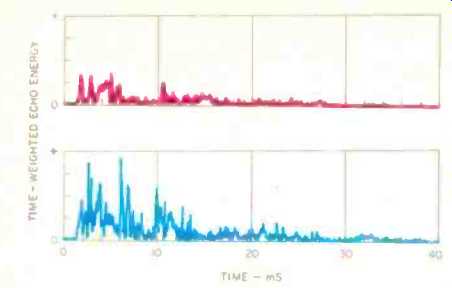
Fig. 16-Echo energy vs. time for MGC-1 (top) and conventional speaker, calculated
from Fig. 15.

Fig. 17-Computed echo-amplitude spectra of MGC-1 and conventional speaker.
(Vertical scale: 10 dB/div.)

Fig. 18-lnteraural cross-correlation (IACC) of single MGC-1 reproducing
white noise.
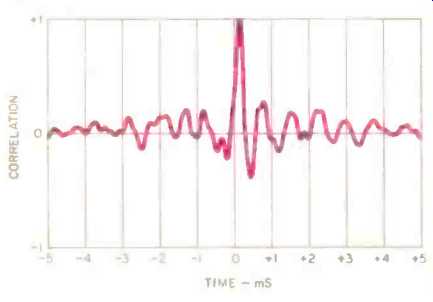
Fig. 19--IACC of single conventional speaker reproducing white noise.
Conclusions
The traditional view of loudspeaker design concentrates on purely physical measurements and ignores many important characteristics of the human hearing system. This approach inherently limits the degree to which subjective loudspeaker performance can be improved. The psychoacoustically ideal speaker has a more complex set of functional requirements. It must deliver to the listener a first-arrival signal that is correct in frequency, time, and direction. It must also provide some means for the user to control the ambient field of the listening room so that this field enhances, rather than distorts, reproduction accuracy.
Our approach to the design of the MGC-1 has been to create a system with optimized, independent radiators for the direct and ambient sound. We believe that the positive reactions of listeners provide the ultimate validation of any loudspeaker design.
References
1. von Helmholtz, H. L. F., On the Sensations of Tone, translated by A. J. Ellis, Longmans and Co., 1885 (reprinted by Dover, New York, 1954).
2. Heyser, Richard C., "Loudspeaker Phase Characteristics and Time Delay Distortion," Journal of the Audio Engineering Society (JAES), Vol. 17, No. 1 (January 1969), pg. 32.
3. Blauert, J. and P. Laws, "Group Delay Distortions in Electro-acoustical Systems," Journal of the Acoustical Society of America (JASA), Vol. 63, No. 5 (May 1978), pgs. 1478-1483.
4. Blauert, J., "Localization and the Law of the First Wavefront in the Median Plane," JASA, Vol. 50, No. 2, Part 2 (August 1971), pgs. 466-470.
5. Kates, J. M., "Loudspeaker Cabinet Reflection Effects," JAES, Vol. 27, No. 5 (May 1979), pgs. 338-350.
6. Atal, B. S., M. R. Schroeder, and K. H. Kuttruff, "Perception of Coloration in Filtered Gaussian Noise--Short-Term Spectral Analysis by the Ear," presented at the Fourth International Congress of Acoustics, Copenhagen, Denmark, 1962.
7. Kates, J. M., "A Perceptual Criterion for Loudspeaker Evaluation," JAES, Vol. 32, No. 12 (December 1984), pgs. 938-944.
8. Salmi, J. and A. Weckstrom, "Listening Room Influence and Ways of Minimizing It," presented at the 71st Convention of the Audio Engineering Society, Montreux, Switzerland, 1982.
9. Beranek, L. L., Acoustics (McGraw-Hill, New York, 1954), pg. 318.
10. Barron, M., "The Subjective Effects of First Reflections in Concert Halls-The Need for Lateral Reflections," Journal of Sound and Vibration, Vol. 15 (1971), pgs. 475-494.
11. Ando, Y., "Subjectively Optimal Conditions of Sound Fields for Recording and Reproducing," presented at the 96th Meeting of the Acoustical Society of America, Honolulu, Hawaii, 1978.
12. Queen, D., "The Effect of Loudspeaker Radiation Patterns on Stereo Imaging and Clarity," JAES, Vol. 27, No. 5 (May 1969), pgs. 368-379.
13. Berkovitz, R., "Digital Equalization of Audio Signals," presented at the Audio Engineering Society Premiere Conference, Rye, New York, 1982.
14. Blauert, J. and W. Cobben, "Some Consideration of Binaural Cross Correlation Analysis," Acustica, Vol. 39 (1978), pgs. 96-104.
(Source: Audio magazine, July 1985)
= = = =