by LORR KRAMER and GREG TIMBERS
-- Lorr Kramer is Product Mgr. Consumer Products of JBL Incorporated, Northridge, Calif.
--Greg Timbers is JBL'S Senior Transducer engineer.
A free-standing, low-frequency loudspeaker system, or sub-woofer, is a proven method of enhancing or, more properly, completing a high-quality, full-range loud speaker system. Simple in concept, the subwoofer provides an elegant solution to several acoustical problems simultaneously. It is the correct choice for the purist, and at the same time is a source of plain old fun.
This article provides the basic information necessary for building a very high performance subwoofer. Many choices are possible along the way; some of these are presented as options, but because this is a construction-oriented article, we have made specific driver and network recommendations to ensure that a properly engineered system will result.
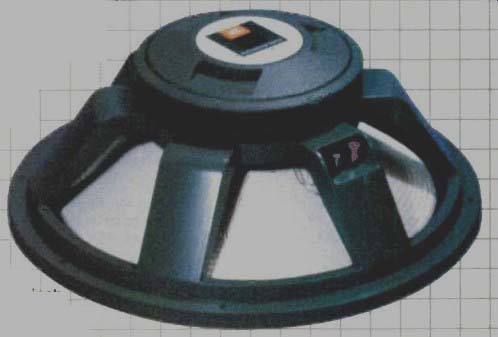
Fig. 1--The JBL Model 2245H 18-inch, low-frequency transducer
Why a Subwoofer?
Obviously, one benefit is lower bass and more of it. If you have shopped around, you know that some devices marketed as "subwoofers" really don't go down very low, not even as low as some good bookshelf loudspeakers.
This article is about the real thing, a box that really reaches into the nether regions of audibility. True, a few full-range loudspeaker systems reach down as deep, but with very rare exceptions they lack the dynamic capability for realism at moderate to high volume levels. Distortion or power compression get in the way-assuming the speakers survive at all! Do the frequencies that are a sub-woofer's specialty really exist in most recordings? Sometimes yes, some times no. Suffice it to say that more and more recorded material includes significant information below 40 Hz. and the trend is accelerating dramatically.
Being the real thing, our subwoofer is crossed over at low level and driven by a separate amplifier. It is possible to achieve this crossover at high level, but the large inductor required for a low crossover point has significant insertion loss and adversely affects the damping of the driver. More important, though, you want to bi-amplify for the distortion and headroom advantages it brings. Remember that the crossover froth the woofer to the midrange, in most three-way loudspeaker systems, occurs above most musical fundamentals.
-------------
------------
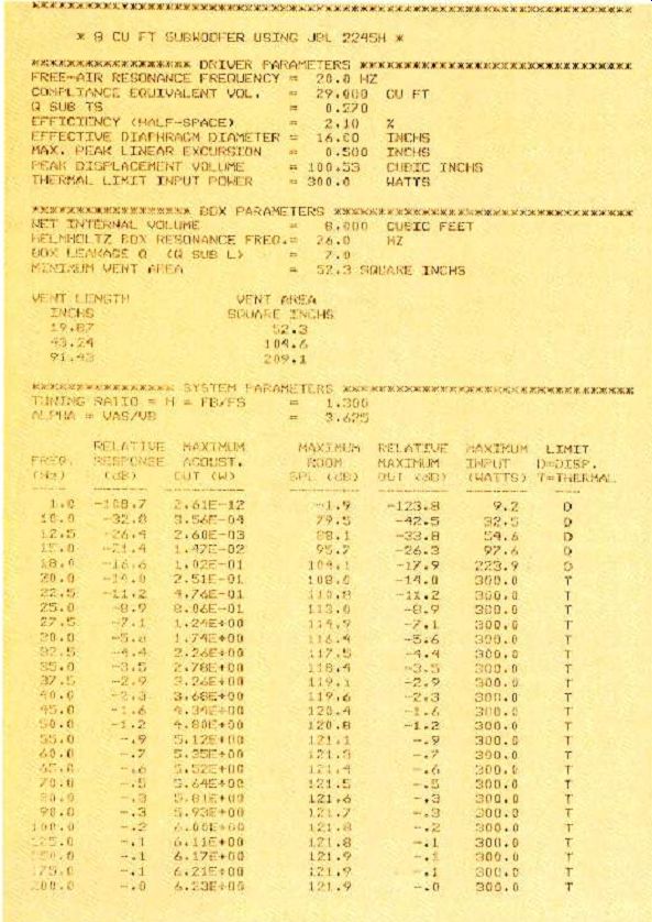
-------- Computer-generated table of the project subwoofer's performance
limits.
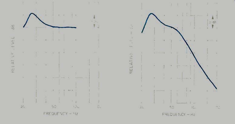
Fig. 2-Equalization required for the 8-cubic-foot project box.
Fig. 3-Voltage drive provided to subwoofer amp by BX63 network. Note its similarity to Fig. 2.
If you intend to use a single sub-woofer, summing the left and right bass channels, you will eliminate most record warp and any other turntable noise or feedback problems which ex press themselves as vertical stylus motion. Such motion appears out of phase in the two channels, and when left and right are summed, it disappears. We are recommending a low crossover point (63 Hz)-in part to minimize any loss of localization information when a single subwoofer is used. Aside from the difficulty in hearing directionality below 100 Hz, many recordings are deliberately summed at lower frequencies for disc mastering considerations.
Nonetheless, stereo subwoofers have some credible adherents. Follow the requirements of your own ears, floor space, and pocketbook.
Speaking of floor space, though good subwoofers are not small, they allow the use of smaller satellite loud speakers, and the total space occupied by all three enclosures could well be less than the space required by a pair of conventional loudspeakers of equivalent performance (assuming such an equivalent exists). There's an economic flexibility as well, in that the satellites and main amplifier can be purchased now, the subwoofer and its electronics later.
By now we hope you want to either buy one of these low-frequency contraptions or build one. Here's how to build one.
The Project Box
Many articles and technical papers have been written on the theory and design of vented-box bass systems, so we will not encumber these pages with the math and physics of the problem.
We chose a vented box primarily be cause of its very low distortion and extended low-frequency cutoff. We did build and audition a properly designed sealed-box subwoofer using the same driver. When the vented and sealed systems were equalized for similar response, the dynamic performance of the vented system was judged to be significantly better.
The driver we chose is the JBL Mod el 2245H (Fig. 1), an 18-inch low-frequency transducer designed specifically for low-distortion, high-level professional bass reproduction. It has a
safe excursion limit of 1 inch, peak-to-peak. Extended bass at reasonable efficiency requires either very large box volume, or large amounts of amplifier horsepower-or both. We sat down with our friendly vented-box designing computer and came away with two interesting candidates. The first is a 12-cubic-foot box tuned to 20 Hz. This is a classic sixth-order alignment requiring 6 dB of boost at 20 Hz and resulting in a system f3 (3 dB-down point) of about 21 Hz. The second contestant is an 8-cubic-foot box, quasi-third-order alignment, tuned to 26 Hz. With 6 dB of boost added at 26 Hz, it becomes a quasi-fifth-order system with an f3 of 26 Hz. For this project, we chose the latter system because of its more moderate size. The 26-Hz cutoff was deemed low enough not to compromise sonic performance.
Our computer provided a table, included here, listing driver parameters and response of the 2245H, and maxi mum output with respect to thermal and displacement limits when installed in the project box. Note the extremely high output levels. This system is the acoustical equivalent of the JBL Model B460 low-frequency loudspeaker.
You might now ask, "Why equalize?" In order to keep the efficiency up and the box size down, we chose to take advantage of the driver's sizable power capacity and the relatively inexpensive price of amplifier power. Notice that the system has an unequalized f3 of about 35 Hz, which means that the extra power demands of the boost only come into play when there is substantial signal below 35 Hz.
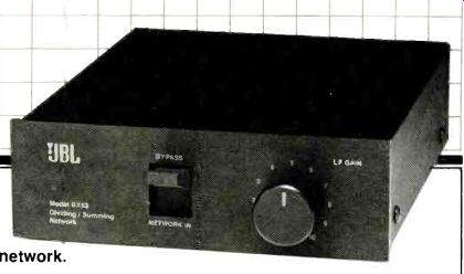
Fig. 4-The JBL Model BX63 dividing summing network.
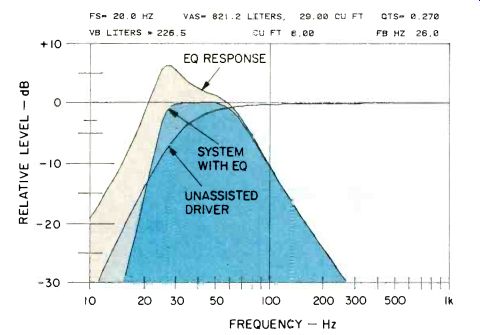
Fig. 5--Response of BX63 network (top curve) and driver's unassisted output
(bottom curve) combine (middle curve) to produce flatter response down
to 26 Hz and greater output above 20 Hz than unassisted driver. Data above
diagram are driver parameters for free-air resonance, compliance equivalent
volume, and total "Q."
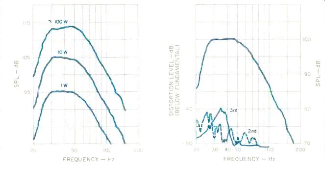
Fig. 6-Power compression of project subwoofer. Note lack of compression
at levels below 10 watts, slight compression above.
Fig. 7-Distortion at 100 dB drive level. Levels shown for second- and third-harmonic products have been shifted up by 20 dB to fit chart recorder.
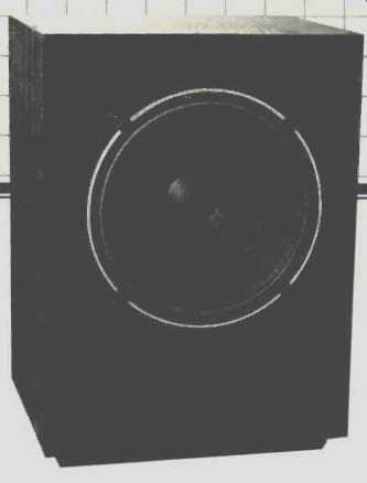
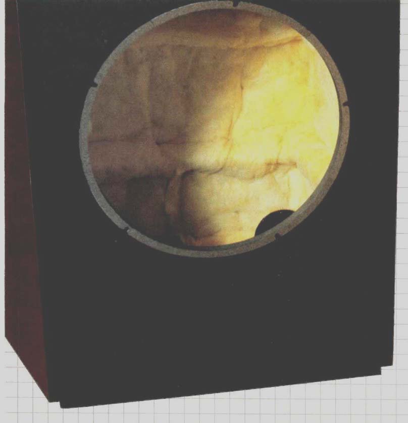
Fig. 8-The 8-cubic-foot project subwoofer with 18-inch driver.
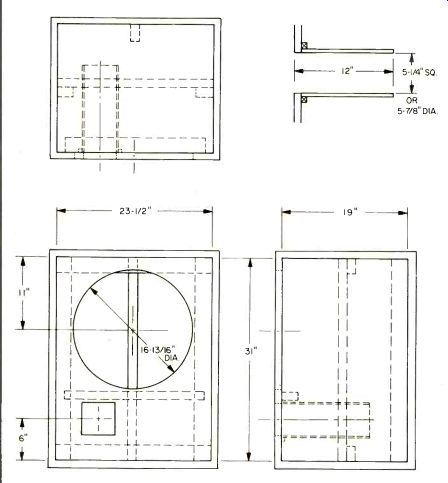
Fig.
9-Construction sketch for 8-cubic-foot enclosure. Dimensions shown are
inside dimensions. Braces, cleats and port duct are shown as dotted lines.
The equalization necessary to flatten the response is shown in Fig. 2. The 2245H can be crossed over as high as 500 Hz, because its midrange response is smooth. A number of low level crossovers suitable for sub-woofers are commercially available.
Figure 3 shows the voltage drive of our recommended crossover, the JBL Model BX63 (Fig. 4), which was chosen for this application because it was designed specifically for the present combination of driver and enclosure.
[Editor's Note: Plans for a crossover you can build yourself are elsewhere in this issue.]
Figure 5 illustrates the combined subwoofer and crossover response with 3 dB-down points of 26 and 63 Hz. The quasi-fifth-order alignment includes a subsonic roll-off to un wanted cone motion below 20 Hz.
The performance of the project box is summarized in Figs. 6 and 7. Figure 6 illustrates power compression. Note zero compression as input rises 10 dB from 1 to 10 watts; output tracks with the same 10 dB rise. Over the next 10 dB, from 10 to 100 watts, only 1 to 2 dB of compression occurs; most loud speakers would never even reach this output level. Figure 7 shows second- and third-harmonic distortion at the 100 dB drive level;-40 dB represents 1% distortion. At this output level, distortion of less than 5% to 10% is very unusual, regardless of loudspeaker type.
Construction
We have built several different en closure shapes for various visual considerations, with no problems acoustically. It is always wise to avoid interior dimensions whose ratios are 2:1, 3:1, 4:1, etc., because such integral ratios often promote severe standing wave problems. For the same reason, it helps to mount the driver approximately one-third of the way down the long side. Our project enclosure (Fig. 8) has internal dimensions of 31 x 23 1/2 x 19 inches. Refer to Fig. 9 for construction details. We recommend 1-inch particleboard or fiberboard, 50-pound density or greater, for the requisite acoustical deadness. Plywood is acceptable, but generally not as dense as composition materials. The panels should be further stiffened by 2 x 4s run the long dimension on each side, top and bottom. These stiffeners should be offset from the panel centers slightly so that they overlap in the corners and can be glued together. A back brace runs from top to bottom and should be cut so that it just touches the top and bottom panels. A baffle stiffener, which should be kept clear of the side panels so that it doesn't buzz, is also used. All stiffeners should be securely glued to the panels with your favorite brand of white glue. The type of joinery used between panels will depend on your expertise and on the type of finish de tails you desire; simple butt joints using plenty of glue and an occasional glue block are completely acceptable for strength.
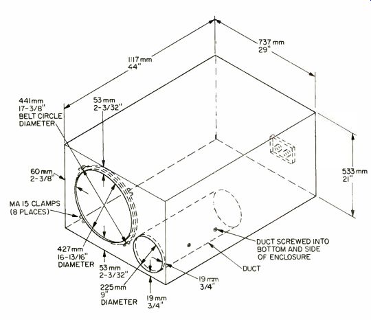
Fig. 10--Plans for a 12-cubic-foot subwoofer enclosure. Exterior dimensions
shown produce correct interior volume when 3/4-inch board is used for walls;
for thicker walls, increase exterior dimensions accordingly. Internal bracing
has been omitted from diagram for clarity (see text). All sides except
the baffle panel are to be with 1 to 2 inch (25 to 50 mm) fiberglass. For
the 25-Hz, unassisted fourth-order alignment, duct length should be 20
inches (508 mm), and a 15 to 20 Hz high-pass filter is strongly recommended.
For the 20-Hz, sixth-order alignment, duct length is 30 inches (762 mm),
and a low-level equalizer with +6 dB boost at 20 Hz and Q = 2 is required.
It is recommended that this unit be used only below 80 Hz, with a monaural
bass sum signal.
The baffle can be permanently attached (glued in place) or removable (using screws and cleats). If it is to be removable, use caulking to make certain there are no air leaks. The box should be lined with fiberglass on the back, sides, top, and bottom. House insulation glass is fine; if it is foil-backed, be sure to place the foil side against the cabinet. The port area should be 27 square inches, and the duct length (including baffle thickness) should be 12 inches. We typically use thick-walled cardboard tubes for our ducts. PVC pipe also works well, as do rectangular ducts fabricated from 1/4-inch masonite or 3/8-inch particleboard.
(For a 27-square-inch area, a round tube's internal diameter should be 5.86 inches.) Remember that as long as the port area is maintained, the cross-sectional shape (round, square, etc.) is not important.
The enclosure proportions are equally suited to lowboy or highboy orientation. We advise you to finish all four sides so that you always have the choice. A non-attached kick base, about 11/2 inches high, can now be fabricated so that the system will appear to hover above the floor. This treatment makes the cabinet appear more finished and less bulky. If you wish to build a grille, allow at least 1 inch clearance in front of the baffle for the 2245H frame thickness and for ward suspension travel. Use an open-weave cloth, and stretch it tightly so that it doesn't flap. Too tight a weave will tend to damp port operation.
Considerable current will be flowing to the subwoofer at times, so use, at the very least, 16-gauge stranded wire or a high-quality loudspeaker cable for your internal connections. Use a good input connector such as a five-way binding post, and solder the internal wire to the back of the terminal. Your external wire run should be as short as possible; use premium cable.
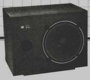
Fig. 11--The JBL 8380, a 4 1/2-cubic-foot subwoofer, using a 15-inch driver.
Alternative Designs
Some of you might be interested in the 12-cubic-foot box mentioned earlier; Fig. 10 gives the necessary construction details. Two systems are possible. The first is a 25-Hz, unassisted fourth-order alignment. The second is a 20-Hz, sixth-order assisted (EQ-required) alignment. The 12-cubic-foot unassisted design gives essentially the same response curve as our 8-cubic-foot project box, and does so without the 6 dB of equalization. Again, the trade-off is enclosure volume versus amplifier power.
If you own stock in the lumber industry and have a direct link to Hoover Dam too, then you can build the 12-cubic-foot, 20-Hz enclosure. It requires 6 dB of boost at 20 Hz, in addition to being huge, but will return a 3 d-down point slightly above 20 Hz. We consider this box to be an interesting exercise, but overkill for almost all pro gram material.
For the rest of you who consider 12 cubic feet way too large and 8 cubic feet a little too large, we have a 4 1/2-cubic-foot offering intended for use with the JBL Model 2235H 15-inch driver. This subwoofer gives essentially the same curve shape as the 8-cubic-foot box, requires the same equalization, and is 4 dB less efficient.
The 2235H handles a little less power, so this system has a 6 dB lower overall output capability (still very substantial, however). All of the construction de tails are the same as for the 8–cubic-foot project box, except that this enclosure was designed with 3/4-inch material. The exterior dimensions are 27 1/2 x 20 3/4 x 17 inches. The port area should be 13 1/2 square inches, and the duct 12 inches long (including the baffle thickness). For the smaller panel sizes of this enclosure, 1 x 3-inch braces are sufficient. This system is equivalent in dimensions and performance to the JBL Model B380 sub-woofer (Fig. 11).
Power Considerations
To provide adequate headroom, no less than 200 watts should be used with any of the subwoofers described.
Significantly better dynamic performance can be achieved with larger amplifiers--assuming, of course, that the main loudspeakers and amplifiers can keep up. A meaningful maximum power limit is difficult to set because of the dynamic nature of music. The continuous sine wave power ratings of the 2245H and 2235H drivers are 300 and 150 watts, respectively. With music as a signal and with the drivers loaded into their enclosures, nominal maxi mum amplifier power guidelines of 800 and 600 watts, respectively, apply. But if you are willing to travel at your own risk, we'll reveal that, in our experience, the bigger the amp, the better. In our listening room, which is rather large and acoustically dead, our 18-inch, 8-cubic-foot subwoofer is connected to 2 kilowatts of power and has never shown any sign of distress even at peak amplifier output. In short, in most cases the bass amplifier will reach its limit before these subwoofers will reach theirs.
If you are using a single subwoofer and don't have a single-channel amplifier handy, a convenient way to get the power is to bridge a dual-channel amplifier. Depending on its power supply and current capability, a bridged amplifier can produce up to four times its per-channel rating. Most bass is transient in nature, so unless it's a sustained organ pedal or synthesizer, you will be able to get peaks of nearly four-times rated power even out of less robust amplifier designs. Of furthercom fort to the bass amplifier is the fact that, with the project subwoofer, maximum EQ boost occurs at vent resonance, presenting close to a purely resistive load to the amplifier at that point.
Some amplifiers bridge at the flip of a switch; at the opposite extreme, non-inverting designs with no bridging pro vision require that the input to one channel be inverted by additional circuitry. The BX63 network mentioned above includes both normal and inverted LF outputs, which will quickly bridge the vast majority of dual-channel amps available.
Setting Up
The optimum placement for a sub-woofer is generally between the full-range systems, and within 3 feet of a line drawn between them (3 feet for ward to 3 feet behind the line). Proper polarity is, of course, critical, and with all the inversions possible in the chain (especially with a bridged amplifier), the best way to check phase is by ear.
Repetitive, percussive bass, such as kick drum or bass guitar, is the material easiest to use for this purpose. To the extent that your room allows, experiment with placement using recordings with deep bass content. Shifts in location of 6 inches can have a perceptible effect.
As a starting point for setting level, the bass gain should be advanced just to the threshold where sound above the crossover point begins to be affected by switching the subwoofer in and out. In any case, it won't take much listening to find the right setting subjectively. Typically, subwoofers are set highest when first installed, out of the owner's enthusiasm for his new toy. If the owner is also the builder, his enthusiasm can be described as maximal.
After the initial fun, the listener usually finds that setting most satisfying which provides the most realism-in other words, real life rather than larger than life. And once you've experienced a good subwoofer, properly set up, nothing short of that performance level sounds like real life.
Acknowledgements
The authors would like to thank W. J. J. Hoge of JBL for setting the stage with his very popular subwoofer article of 1976 in these pages. His work made our efforts quite straightforward. We would also like to thank D. B. Keele, Jr. (JBL) for his kind assistance with the computer. His efforts made the special voltage drive of the BX63 a reality. Finally, we would like to credit Douglas Warner of Warner Design, Berkeley, Cal. for the proportions of the 8- and 5 cubic-foot enclosures (and the industrial design of the 2245H, BX63, 8460, and B380).
References
Hoge, W. J. J., "Switched On Bass," Audio, Aug. 1976 ("Addenda," Nov. 1976, pg. 24); "Confessions of a Loudspeaker Engineer," Audio, Aug. 1978.
Keele, D. B., Jr., "Low-Frequency Loudspeaker Assessment by Nearfield Sound-Pressure Measurement," Journal of the Audio Engineering Society, April 1974; "A New Set of Sixth-Order Vented-Box Loud speaker System Alignments," JAES, June 1975; "Direct Low-Frequency Driver Synthesis from Systems Specifications," JAES, Nov. 1982.
Small, R. H., "Vented-Box Loudspeaker Systems, Part III: Synthesis, JAES, Sept. 1973.
==========
(source: Audio magazine, Aug. 1983)
Also see:
Crossovers for Subwoofer Biamping (Aug. 1982)
Thunder in the Listening Room--Subwoofer Shootout (Nov. 1992)
Muffling the Neighbors: Ten Tips to Reduce Noise (Nov. 1990)
Build A Center Woofer Crossover (Aug. 1983)
= = = =