
Manufacturer's Specifications:
Frequency Response: 20 Hz to 20 kHz, ± 0.1 dB; 1.5 Hz to 500 kHz, ± 1.5 dB.
RIAA Equalization Accuracy: ± 0.25 dB, 20 Hz to 20 kHz.
THD and IM Distortion: Less than 0.01% below 18 V output.
S/N: MM phono, 85 dBA; MC phono, 80 dBA; high level, 100 dB; all re: 3 V out.
Input Sensitivity: MM phono, 2.3 mV; MC phono, 115 µV; high level, 315 mV.
Input Overload at 1 kHz: MM phono, 165 mV; MC phono, 8 mV; high level, infinite.
Dimensions: 19 in. W x 1 3/4 in. H x 8 3/4 in. D (48.3 cm x 4.4 cm x 22 cm)
Price: $729.
Company Address: 21300 Superior St., Chatsworth, Cal. 91311. USA.
The Athena is a new preamp from Sumo that replaces their older Electra unit. Unlike the Electra, the Athena does not use IC operational amplifiers; it has more than 100 discrete transistors in its circuitry. Although the Athena's uncluttered front panel does not have tone controls, it does have ample facilities, including a switchable MC stage, separate switches for tape recording and input selection, and plenty of high-level and tape recorder inputs.
Front-panel controls, from left to right, are a pushbutton power switch; a rotary tape record selector; a rotary input selector; concentric, rotary volume and balance controls, and pushbutton switches for mono/stereo, for the low-cut filter, and to bypass the output line amplifier. On the rear panel are a two-wire power cord, gold-plated input and output signal jacks, and a chassis grounding post.

The construction of this preamp is relatively simple and straightforward, utilizing a single piece of sheet steel that is bent up to form the bottom, sides, and rear panel. An extruded piece of aluminum, backed with a piece of sheet steel, forms the front panel and, via a short lip along the bottom of the extrusion, is attached to the chassis bottom piece. The piece of sheet metal backing the front panel has rear-facing tabs, about an inch long, on each end; the rear panel has similar forward-facing tabs. Two Pem nuts are arranged vertically on each of these four tabs. A top cover with sides fits over this assembly. A pair of rack Handles is bolted onto the front subpanel tabs. A pair of short machine screws bolts through the top cover sides into the rear tabs.
It all fits together nicely, but the metal seems a bit thin.
Circuit Description
Figure 1 is a block diagram of the Athena's signal flow.
This preamp uses the increasingly popular scheme of separate selector switches, one for record out and the other for listening. Two additional switch poles per channel on the tape record selector switch are wired into the output of the tape output buffer circuit, to prevent output-to-input feedback in connected tape recorders or other signal processing devices. This works by grounding the feed to tape out of the selected tape input. This really necessary completeness of design is something that I don't believe I've seen in other units that use the dual-selector scheme.
The low-cut filter has a slight flaw regarding its effectiveness in the tape-out path. If phono is selected for recording but not for listening, and the low-cut filter is engaged, the cutoff frequency of the filter becomes much lower than when phono is selected for listening. This is because the resistances of the volume and balance controls aren't loading the low-cut filter's series capacitor. However, when phono is selected as the listening source, the cutoff frequency is as intended,' for use in reducing acoustic feedback and/or woofer excursion due to warped records when listening through the preamp's line output section.

Fig. 1--Block diagram (one channel shown).

Fig. 2--Simplified schematic of circuit used for phono-preamp and x10 line-output
sections.

Fig. 3--In the phono equalization section, a loading network (Z1, in Fig.
2) shapes the circuit's open-loop gain to follow the RIAA curve, and negative
feedback is constant over the audio range and beyond.
Bypass switches are becoming increasingly popular on preamps, with two kinds in use today. One type bypasses the mode and balance controls when engaged. The other type, used by Sumo in the Athena, bypasses the preamp's line output amplifier, for greater signal purity. There are three considerations regarding whether one can get away with not using a line output amplifier: Adequate gain, high-frequency roll-off due to cable capacitance in the preamp-to-amp connecting cable or in the input circuitry of some power amps, and overall sound-quality improvement possibilities without a line amplifier in the signal path.
About gain: Most signal sources, even many phono preamp outputs, have enough output level to drive the majority of power amplifiers and speakers to a reasonable level. Whether or not the volume attainable in a system without the extra gain of a preamp line amp is satisfactory depends on your definition of reasonable volume, the phono cartridge output, the phono preamp gain, the sensitivity of the speakers used, and the gain or sensitivity of the power amplifier. A relatively easy way to find out if enough volume would be attainable in your system without a preamp line stage is to select the weakest signal source (usually, but not necessarily, phono), turn off the system power amplifier, and then plug the amp input leads into the preamp's tape outputs rather than its main outputs, where they had been.
Next, turn the power amp back on and listen to the selected source. If the volume is loud enough, or perhaps more than loud enough, you could use a preamp with an output amplifier bypass mode or make an external volume control in a box chassis and interpose it between tape out and power amp input. I have been using an external volume control this way for some 25 years with my sound systems.
High-frequency roll-off: A variable, first-order (6-dB/octave) low-pass filter is formed by the shunt cable capacitance and the resistance looking back into the wiper of the volume control. The highest resistance, and consequent lowest cutoff frequency, is with the control set about 6 dB down from full volume, where it will surely be when the Athena is in bypass mode. A popular resistance value for volume controls, and the value I usually use, is 50 kilohms.
The worst-case impedance looking back into the wiper is about one-fourth of the pot's resistance, or 12.5 kilohms. A check of some 1-meter interconnects that I happen to have on hand yielded total capacitances of about 160 to 360 pF, which would cause response to be 3 dB down at 79 and 35 kHz, respectively. Some people could hear such filters if inserted into an otherwise wider bandwidth system, but the improvement in sound quality without a line stage could be worth it. If one needs longer cable runs to the power amplifier, then the worst-case high-frequency cutoff point moves down. A 10-kilohm volume control raises the high-frequency cutoff by a factor of five. However, 10 kilohms is generally too low a load impedance for most tube sources to drive happily. Often, some compromise is needed to resolve these conflicting requirements.
Sound quality: This is the main reason for being nuts like this. The above considerations aside, the bottom line for me is that I prefer the sound that I get using my present, 50kilohm switched attenuators over any preamp line stage (and its internal switches, wiring, and balance and volume controls) that I've heard so far.
In the case of the Athena, a unity-gain buffer circuit is in the signal path between the volume control wiper and the x 10 line-out amplifier circuit. The bypass mode selects the output of the unity-gain buffer instead of the output of the x 10 amplifier. This use of the unity-gain buffer keeps the high-frequency response wide even when the interconnect cables cause capacitive loading, but it does so at the price of inserting an extra active circuit in the signal path. Further, in normal mode, there are two output amplifiers in series rather than the one that would be present if the unity-gain buffer amp weren't used.
Another little subtlety in the signal path warrants comment. When a preamp has a mono/stereo switch, usual practice is to have a resistor in series in each channel such that, when the mono mode is engaged, the channels are tied together at these resistors' output ends. This ensures that the source will not be excessively loaded with out-of-phase signal currents from the opposite channels. In the Athena, the series resistors are only switched in for the mono mode. In stereo, no series resistors are in the signal paths, thus enhancing high-frequency response. When the Athena's mono mode is engaged, a level drop of 3 dB occurs in each channel, presumably to make the acoustic mono sum come out at the same level as the stereo signals.
The actual circuits used for the various blocks are of three basic types: Simple circuit with voltage gain (used in the MC pre-preamp), complicated circuit with gain (phono and x 10 line amp), and unity-gain voltage follower (tape-out and unity-gain line-amp buffers). Starting with the MC pre-preamp, we have a circuit topology consisting of a cascade of common-emitter, common-emitter, and common-collector (emitter-follower) stages.
The first stage is made up of two paralleled NPN transistors in a common case; its emitter-to-ground resistance is a fairly low 22 ohms for low equivalent input noise. The second stage is a PNP transistor with a fairly large, bypassed emitter resistance along with a much lower value of unbypassed resistance. The input of this second stage is direct-coupled from the output of the first stage. The collector output of the second stage is direct-coupled to an NPN transistor, functioning as an emitter follower. Overall negative feedback is applied from the last-stage emitter (which is the circuit output) to the first-stage emitter, for a resistor-determined circuit gain of 22 x . The main power supply of ±35 V is divided down, capacitor-bypassed to about ±5 V, and applied to the moving-coil circuit through emitter-follower pass transistors. Signal input and output are capacitor-coupled in this circuit.
This leads us to the complicated circuit with gain used in the phono preamp and x 10 line amp; a greatly simplified schematic of this topology is shown in Fig. 2. The basic principle seen here is the use of a non-complementary differential amplifier in which both output phases are used to create a complementary output signal. (This topology has been used in power amplifiers before. I first saw it in the Marantz 510, and I believe I have seen it used recently in some high-quality car amplifiers.) Here, Q1 and Q2 function as the input differential amplifier. The collector of Q1 drives the base of Q4, whose collector output has the correct polarity to drive the emitter-follower output stage so that negative feedback can be returned to the base of Q2. The collector of Q2 is out of phase with the signal at Q1's collector. By applying the signal from Q2 to the base of Q3, a phase-inverted and level-shifted signal appears at the base of Q5, which is in phase with the signal at Q4's base.
The two phases from the output of the differential input amp are thus added to form the composite signal appearing at the collectors of Q4 and Q5. The phase inversion in Q3 occurs because the signal across R1 is very close in amplitude to the signal at the base of Q3 due to "emitter following." Since R1 is equal to R2, whatever is developed across R1 is transferred, in opposite polarity, to R2 because the current in R2 is the same as in R1, except for a small amount of base current. D1 and D2 are biasing diodes for the output transistors Q6 and Q7. As mentioned, Fig. 2 is a conceptually accurate but simplified schematic of the phono circuit.
The actual circuit has eight transistors in its input differential-amp circuit, uses two transistors plus a diode-connected transistor for Q3, and uses cascaded emitter-follower pairs for Q4 through Q7, making a total of 19 transistors used in one channel of the phono preamp.
In the use of this circuit as a phono equalizer, Sumo has used an interesting (though not original) idea of having the network Z1 load the collectors of Q4 and Q5 such that the open-loop gain of the circuit follows the RIAA characteristic.
Then, with overall feedback applied through Z2 (which is a series impedance network for producing the RIAA curve), the amount of negative feedback is constant over the audio range and beyond. (See Fig. 3.) Next, we look at the voltage-follower circuit used as a tape-out buffer. (Refer to Fig. 4.) This is essentially a complementary, cascaded emitter follower. The bases of Q1 and Q2 are tied together and are driven through the input coupling capacitor. The emitters of Q1 and Q2 will be up and down about 0.6 V, which is just what is required to bias Q3 and Q4 into conduction. The values of resistors R3 through R6 are selected so as to allow the desired idling current in Q3 and Q4. This topology, including Q1 and Q2, permits biasing Q3 and Q4 without a resistor/diode network, which would lower input impedance. Capacitor C2, from the circuit's output to the midpoint of R1 and R2, bootstraps R1 to a higher effective value than its actual resistance. For instance, if the overall gain of the circuit were to be 0.9, R1 would appear 10 times higher or, to be more precise, the circuit input impedance would be 10 times the value of R1 in parallel with the reflected impedance at the bases of Q1 and Q2.

Fig. 4--Simplified schematic of the voltage-follower circuit used for the
tape-output and unity-gain line-output buffers.

Fig. 5--Power-supply regulator circuit; see text.
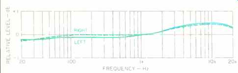
Fig. 6--RIAA equalization error, MM mode. Error in MC mode was essentially
the same.
The voltage follower used in the unity-gain output amp is like the circuit of Fig. 4 except that R3 and R4 are replaced by current sources. In addition, the supply voltage to this circuit is reduced to about ±20 V by placing 15-V zener diodes in series with the supply feed lines.
In the x 10 output amplifier, the circuit is exactly like the phono preamp except that the network Z2 is set for a flat, wideband gain of 20 dB. Network Z1 consists of a resistor and a series RC network in parallel to limit open-loop gain and roll it off above about 130 kHz.
The power supply in the Sumo Athena produces regulated ± 35 V for all circuit blocks. With the exception of the MC circuits, each circuit block is decoupled by a 10-ohm series resistor and a 0.1-µF capacitor to local ground for the positive and negative rails. The moving-coil circuits have their own local positive and negative regulators.
A toroidal power transformer feeds a full-wave bridge rectifier composed of individual diodes, which in turn feeds a capacitor input filter with 2,000 µF each for the positive and negative unregulated voltages.
The regulator circuitry (Fig. 5) is unusual in a number of interesting respects. First, the series pass devices are connected in a common-emitter mode rather than the more usual common-collector (emitter-follower) configuration.
Second, the error amplifier, which in simpler regulator circuits has a zener diode in its emitter circuit as the regulator reference voltage, is configured like a differential amplifier but with opposite-sex devices rather than the usual, same-sex configuration. A slow turn-on of the power supply is achieved by an RC network, buffered by an emitter follower, across the reference zener diodes. One disadvantage of the error-amplifier circuit used here is that the base-to-emitter voltage change with temperature is not reduced by regulator feedback; in fact, the regulator output voltage would drift some four to five times as far, in millivolts, as either error-amp transistor. This is probably not a problem in this preamp, though, as the internal temperature is rather high and reasonably constant.
Lastly, another circuit controls the output muting relay which, upon turn-on, delays the un-shorting of the outputs by 10 to 15 S and, when the unit is turned off, shorts the outputs immediately.
Phew! What a circuit! Definitely not of the "simpler is better" school of design.

Fig. 7--Square-wave response through the MM phono input, at 40 Hz (top), 1
kHz (center), and 10 kHz (bottom). The lower amplitude trace of each pair is
with IHF loading, the other trace with instrument loading.
(Scales: Vertical, 1 V/div.; horizontal, 5 mS/div. for 40-Hz signals, 200 µS/div. for 1 kHz, and 20 µS/div. for 10 kHz.)

Fig. 8--Response to 200-kHz square waves via high-level inputs, for normal
mode (top) and bypass mode (bottom). Waveforms for both IHF and instrument
loading are superimposed. (Scales: Vertical, 5 V/div. in normal mode, 0.5 V/div.
in bypass mode; horizontal, 1µS/div.)

Fig. 9--Same as Fig. 8 but for 20-Hz square waves. (Horizontal scale: 10 mS/div.)
Measurements
Circuit gains and IHF sensitivities were measured first, and results appear in Table I. Phono and output amplifier noises are enumerated in Table II for various bandwidths and source impedances. Noise in MM mode was satisfactorily low, and MC noise was among the lowest I have measured in a preamp for quite a while. IHF signal-to-noise ratios for all inputs are shown in Table III.
RIAA equalization error for MM mode, as measured at tape out, is shown in Fig. 6. Since the MC pre-preamplifier circuit's response was flat, the equalization error in MC mode looked essentially like Fig. 6. A 'scope photo of various square waves through the MM phono circuit is shown in Fig. 7. Each trace is for instrument and IHF loading, with the lower amplitude waveform being for IHF loading.
MM phono THD + N at 15 V rms output, as measured at the tape output, was about 0.02% from 1 to 20 kHz, increasing to about 0.05% at 200 Hz, 0.1% at 50 Hz, and 0.2% at 20 Hz for the left charnel. The right channel stayed at about 0.02% down to 50 Hz and rose to 0.03% at 20 Hz. At a more moderate and realistic level of 5 V rms, THD + N was less than 0.01% from 20 Hz to 20 kHz for both channels. Left-channel MM phono overload versus frequency, for instrument and IHF loading, is shown in Table IV; the right channel was very similar in behavior. Moving-coil input voltages for phono output overload are roughly 20 times lower than shown in the Table. It is very unlikely that any moving-magnet cartridge out there is going to overload the Athena's phono circuitry. However, if a high-output moving-coil pickup with nominal output of 1 to 2 mV is fed through the MC pre-preamp, there could be trouble if the peak levels on the record reach 14 dB above the nominal 3.54-cm/S output. I would recommend that such pickups be used in the moving-magnet mode.
Phono crosstalk versus frequency was found to be greater than 80 dB up to about 500 Hz, decreasing to about 66 dB at 3 kHz and to about 50 dB at 20 kHz. These results were about the same in both directions (R to L and L to R) and for source impedances up to 1 kilohm. With the IHF MM simulated source, the figures were only about 3 dB worse in the region of 10 kHz, which is outstanding. Crosstalk in MC mode was about the same as for MM. All crosstalk for the phono circuitry was in phase.
In assessing the performance of the line-amp section, one of the first things I checked was input overload levels for the high-level inputs with the volume wide open and in the bypass mode. For a signal input of 3 V rms, which was clipping the x 10 amp, the output of the unity-gain amp (which is the preamp output in this mode) was still clean, with no distortion artifacts caused by clipping in the following circuit. These are unlikely conditions of use. If the source delivered more than 2 V rms, the volume control would probably not be turned up most of the way. Exceptions would be to make up for an excessively low speaker sensitivity or for a power amp with unusually low gain or with its input level control turned down too far.
In the normal output amp mode, using the x 10 amp, the Athena could put out 20 V rms into an IHF load with less than 0.01% THD + N from 20 Hz to 20 kHz. Impressive! Further, with a 600-ohm load, THD + N was less than 0.01% from 20 Hz to 20 kHz at 13 V rms output for the right channel and 11.5 V for the left.

Table I--Gain and IHF sensitivity for IHF load, normal mode. In bypass mode,
sensitivity for main outputs will be 10 times less, and input levels will be
10 times more for reference output of 0.5 V. Gain figures for instrument load
or loads more than 100 kilohms are 0.1 dB greater for main outputs and 1.0
dB greater for tape outputs.

Table IIA--Phono-section noise, referred to input. With zero-ohm input impedance,
noise measured in wideband mode was basically subsonic, decreasing as frequency
increased (a characteristic).

Table IIB--Line-amp section noise, referred to input with x 10 (normal) gain
setting and 1-kilohm input termination, for fully clockwise volume-control
settings and worst-case settings (usually about 6 dB below full clock wise).

Table III--Signal-to-noise ratio.

Table IV--Moving-magnet phono overload vs. frequency, left channel.
The detented volume control used in the Athena was checked for tracking error and step consistency for each of its 30 positions. Channel-to-channel tracking was within 0.7 dB down to50 dB and within 1.6 dB to70 dB. The steps are finer (less than 1 dB) near full clockwise and get larger as the control is turned down. There were a few glitches in the control's attenuation curve. Attenuation per step decreased from 3.9 dB at the 20th position from full clockwise to 1.7 dB at the 21st. Also, the rate of attenuation dropped from 5.3 dB at the 25th position to 2.2 dB at the 26th. The audible consequence of this would simply be a different volume increment through these positions compared to the neighboring positions.
Output amplifier bandwidth and speed were next looked at. With volume fully clockwise and normal mode engaged (i.e., using the x 10 amp), rise- and fall-times were 100 nS with instrument load (90 kilohms in parallel with 200 pF) and 200 nS with the IHF load (10 kilohms in parallel with 1,000 pF) at an output level of 10 V peak to peak. Switching into bypass mode gave rise- and fall-times of 60 and 100 nS, respectively, for instrument and IHF loads. These circuits are fast! Turning the volume control down about 6 dB slows things down to about 0.5 µS with either load. Worst-case speed degradation was with the balance control partially off to one side; rise- and fall-times lengthened to about 1 µS, still equivalent to a bandwidth of about 350 kHz. 'Scope photos of square waves through the line output amplifiers are shown in Figs. 8 and 9. Figure 8 is for 200-kHz square waves, with the volume control set fully clockwise. Shown in the top trace is the output of the x 10 amp at 10 V peak to peak. The faster rise- and fall-times on the traces are for the instrument load. On the bottom trace, the bypass mode is engaged. Output is 1 V peak to peak. Figure 9 is for 20-Hz square waves. In the top trace, the output is shown for the x 10 amp; the bottom trace is for the output of the unity-gain amp. Note the greater low-frequency tilt in the x 10 amp. In both of these traces, instrument and IHF loadings are shown, although it's hard to see any difference.
Crosstalk of the line section was measured with volume full up, balance at center, x 10 mode used, and a 1-kilohm resistor terminating the input of the undriven channel.
Crosstalk between channels was greater than 80 dB up to about 1 kHz, decreasing to about 62 dB at 10 kHz and 57 dB at 20 kHz. With the balance control set to attenuate the undriven channel by 2 or 3 dB, the crosstalk increased some 10 dB at 10 kHz. The results were symmetrical in both directions, and crosstalk was in phase.
Line-section IHF sensitivities, gains, IHF signal-to-noise ratios, and noise referred to input for various conditions appear in Tables I, II, and III.
I noticed with the cover off and the unit fully warmed up that the output devices in some of the circuit blocks, notably the phono preamp, were running a bit too hot, in my opinion, and should have some heat-sink radiators attached.
Use and Listening Tests
Equipment used to evaluate the Sumo Athena included an Oracle turntable fitted with a Well Tempered Arm and a Koetsu Black Goldline cartridge, a California Audio Labs Tempest CD player, a Nakamichi 250 cassette deck, Cook-King reference and Motif MC8 preamps, and Classic Audio CA260 and Motif MS100 power amplifiers driving Siefert Research Magnum III speakers.
When listening to CDs, tuner, and tapes through high-level inputs, I preferred the sound with the Athena's bypass mode engaged. By contrast, the normal mode wasn't quite as open and was a bit less defined-but I'm talking about fairly subtle differences here. When comparing the sound of the line section (which in any preamp includes not only the sound of the output amplifier circuitry per se but also the sound of the internal wiring, switches, and level controls) to a passive switched set of attenuators that I frequently use, I felt the Athena sounded noticeably more electronic, less open, and with less feeling of the instruments actually being in the room.
When playing records, I used the MM mode for the majority of my listening. I found overall reproduction to be pretty good, with reasonable openness and detail although with a sense of being a bit dry and spatially flat. Signal-to-noise ratio was okay for me in this mode, although, with the arm off the record, I could hear hiss from the speakers at playing level when I got closer to the speakers and listened for noise. Most of my listening was with the Classic Audio CA260 tube power amp. The overall sound was a little forward and aggressive but not edgy or irritating. When I used the Motif MS100, the sound was more laid back and smoother. I didn't have a chance to pair the Athena with a Sumo Polaris power amp, which is an obvious combination, but my sonic memory of the Polaris' sound leads me to believe that the combination would be sort of mid-way between.
The question of which might sound better--MM phono with x 10 output an-p (needed to get enough playing gain) or MC phono with unity-gain output amp mode--was answered in favor of the former, with MC loading of 100 ohms as installed at the factory. When I attempted to unload the MC input with a higher load, like 47 kilohms, I got excessive woofer-cone excursion in the range from 1 to 10 Hz and not-so-good sound. I tried to simulate this condition in the lab, and indeed the Athena acted as though some high-frequency oscillation was occurring (presumably in the MC pre-preamp) when the MC load resistance was 47 kilohms. The subsonic frequency response looked okay, i.e., not peaked like I got in the listening setup. When the 100-ohm loading resistors were reinstalled, the unit acted normally. This phenomenon may be a peculiarity of my sample.
I did listen quite a bit to the Athena and got good musical satisfaction from it. When one considers its price, it gives good performance and value for the money.
--Bascom H. King
(Source: Audio magazine, Aug. 1989)
Also see: Sumo Delilah Crossover (Aug. 1988)
Sumo Model Nine Amplifier (Dec. 1983)
Superphon C.D. MAXX Preamplifier (Dec. 1988)
= = = =