
MANUFACTURER'S SPECIFICATIONS:
Usable Sensitivity: Mono, 9.3 dBf (1.6 p V, 300 ohms).
50-dB Quieting: Mono, 14.7 dBf (3 NV); stereo, 36 dBf (35 p V).
S/N: Mono, 80 dB; stereo, 75 dB.
THD, 100 Hz, 1 kHz and 6 kHz: Mono, 0.05 percent wide, 0.15 percent narrow; stereo, 0.07 percent wide, 0.2 percent narrow.
Frequency Response: 30 Hz to 15 kHz, +0.3 dB, -1.0 dB.
Capture Ratio: 1.0 dB.
Selectivity: 45 dB wide; 80 dB narrow.
Image and I.F. Rejection: 115 dB.
Spurious Response Rejection: 90 dB.
AM Suppression: 65 dB.
Muting Threshold: 15 pV (28.7 dBf).
Stereo Separation: Wide, 45 dB @ 1 kHz, 40 dB @ 100 Hz and 10 kHz; narrow, 45 dB @ 1 kHz, 40 dB @ 100 Hz and 10 kHz.
Sub-Carrier Rejection: 65 dB.
SCA Rejection: 70 dB.
Output Level: 0.775 V fixed; 0 to 1.5 V variable.
General Specifications Power Requirements: 120 V, 50/60 Hz, 25 watts.
Dimensions: 19 in. (45.25 cm) W x 5 3/8 in. (14.23 cm) H x 12 1/8 in. (32.7 cm) D.
Weight: 16 lbs (7.5 kg).
Price: $600.00
-------------

Whether on the test bench or installed in a hi-fi system, Rotel's top-of-the-line RT-2100 stereo FM tuner turns out to be a rather fine performer. While we could quibble with the owner's manual describing this unit as having an AM section--there is none--this really is pretty minor. In any case, the front panel is sized for standard rack mounting and is complete with properly spaced screw-notches at each end and a pair of rugged looking handles. The dial area is pan-handled in shape, carrying over an asymmetrical style that has become identified with other Rotel products, such as their amplifiers and receivers. In this instance, the irregularly shaped cutout serves a definite purpose. The "deep" portion of the cutout at the left incorporates the combination LED signal-strength metering system/multipath indicator, a four-digit digital readout of tuned-to frequencies, "tuning" and "locked" LED indicators (about which more in a moment), and a stereo indicator light. Running the full length of the cutout is a linearly calibrated FM frequency scale, with each MHz divided into four marked increments (250 kHz each?), and a conventional moving dial pointer.
The power On-Off toggle switch is at the lower left, while at the lower right are a rotary output level control, an i.f. bandwidth switch (with "Wide" and "Narrow" settings), muting On/Off switch, a mode selector switch (with positions for Auto-FM, Mono, Dolby FM, and Stereo Only, and the flywheel-coupled rotary tuning knob. Three small push buttons just under the dial opening in this area of the panel are used for altering the signal-strength LED display to a multipath indicator, introducing a high-blend filter (for weak-signal stereo reception), and activating a built-in 400-Hz record-calibration tone.
To the right and left of the aforementioned "tuning" indicator LED (which is colored green) are a pair of red arrows which tell the user which way to tune to attain optimum tuning. The touch-lock tuning system of the unit is by now familiar to most readers, since this approach has been used by several tuner and receiver manufacturers. So long as you grip the tuning knob, the built-in, quartz-referenced, phase-lock-loop type of AFC is deactivated. Once you have tuned to a station (as indicated by the red and green LED combination of indicators) and release the knob, this sophisticated form of AFC "locks" onto the signal and counteracts any drift or compensates for slight detuning. Releasing the tuning knob causes the "locked" light to come on, giving the user the visual assurance that, indeed, optimum tuning has been achieved and will be maintained. Though the owner's manual does not indicate it, this ultra-sophisticated circuit can be deactivated by turning off the muting switch, and we used this setting for our distortion measurements to get around a slight misalignment in the auto-lock circuit of this sample. As we will see later, this manual tuning resulted in truly magnificent distortion figures obtained in our bench tests.
The rear panel is equipped with 300-ohm and 75-ohm antenna terminals, the latter being available either as a terminal or in the form of a coaxial connector. In addition to the pairs of fixed and variable-level output jacks, there is a detector output jack for possible use if and when four-channel stereo FM broadcasting is approved.
No information regarding circuit configuration is provided in the multi-lingual owner's manual, but an examination of the internal layout of the chassis disclosed a five-gang tuning capacitor, a well-shielded front-end and i.f. section, and generally neat and orderly layout of the major and minor circuit boards. The well-marked adjustment points (all in English, this time) would make servicing and alignment of this unit fairly easy to accomplish, and we were tempted to "touch up" the auto-lock circuitry but refrained from tampering with the factory settings.
Laboratory Measurements
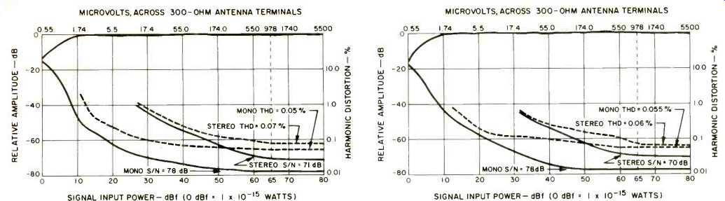
Fig. 1--Mono and stereo quieting and distortion characteristics of the
Rotel RT-2100 in "wide" i.f. mode, 1 kHz, 100 percent modulation.
Fig. 2--Mono and stereo quieting and distortion characteristics in "narrow" i.f. mode, 1 kHz, 100 percent modulation.

Fig. 3--THD vs. frequency in the "wide" i.f. mode.
Fig. 4--THD vs. frequency in the "narrow" i.f. mode.

Fig. 5--Stereo FM frequency response (upper trace) separation (lower trace),
and separation with MPX filter (middle trace) in the "wide" i.f.
mode.
Fig. 6--Stereo FM response (upper trace) and separation in the "narrow" i.f. mode.
Two sets of measurements of most parameters were required for this report; one for the "wide" i.f. mode, the other for the "narrow" mode. In the "wide" setting, usable sensitivity in mono was 10.7 dBf (1.9 pV), while signal strength for 50-dB quieting measured an incredibly low 10.3 dBf (1.8 NV) in mono and an also impressively low 34.7 dBf (30.0 pV) in stereo. Signal-to-noise ratio at 65 dBf in mono was 78 dB, decreasing to 71 dB in stereo; both figures are a little poorer than claimed but certainly more than simply adequate. For a 1-kHz signal, THD measured 0.05 percent in mono and an almost as good 0.07 percent in stereo. These quieting and distortion characteristics are plotted as a function of input signal strength in Fig. 1.
Figure 2 is a plot of the same characteristics, this time for the "narrow" i.f. setting. The mono 50-dB quieting point was a bit poorer this time, with readings of 2.5pV (13.2 dBf), though ultimate S/N remained the same for mono, decreasing slightly to 70 dB for stereo. An unusual thing about this setting was that the THD for 1kHz was just about as good as it had been in the "wide" setting, measuring 0.055 percent in mono and 0.06 percent in stereo, the latter figure actually a shade better than in the "wide" mode. As can be seen from Figs. 3 and 4, there is a moderate improvement in distortion when using the "wide" i.f. setting as far as the frequency extremes are concerned. Thus, in the "wide" mode, THD at 100 Hz and 6 kHz measured 0.07 percent and 0.095 percent in mono respectively and 0.09 percent and 0.11 percent in stereo, while for the "narrow" mode, THD in mono at 100 Hz and 6 kHz measured 0.075 percent and 0.13 percent, and for stereo the readings were 0.15 percent and 0.1 percent. Based on the all-around excellence of these distortion measurements alone, one could not totally justify the added expense of providing the two i.f. bandwidth selections, what with the level of performance attained by the "narrow" section.
In the case of stereo separation, however, the availability of these two modes proved to be of somewhat greater significance, as can be observed in Figs. 5 and 6. The lower trace of Fig. 5 is a plot of cross-talk, or output in the right channel when a left-only signal is used to modulate the carrier. Separation at the three key test frequencies of 1 kHz, 100 Hz, and 10 kHz measured 49 dB, 43 dB, and 47 dB. The middle trace in Fig. 5 shows what happens to separation when the high-blend filter is introduced to reduce noise from weak-signal stereo signals. Figure 6 shows separation versus frequency using the "narrow" i.f. mode. Separation decreased to 43 dB at 1 kHz, 44 dB at 100 Hz, and 37 dB at 10 kHz. Vertical calibration in the 'scope photos of Figs. 5 and 6 is, as usual, 10 dB per vertical division.
Discerning readers may note that the meter-read separation figures just quoted do not always agree with the ob served cross-talk in our frequency-sweep spectrum analyzer 'scope photos. That is because a single-meter reading of cross-talk includes output products in addition to the fundamental modulating frequency fed to the other channel. Figure 7 illustrates this point and was taken with a 5-kHz signal applied to the left channel (tall spike at left) and using a linear sweep of the analyzer (5 kHz per horizontal division).
Storing the 5-kHz spike, a sweep was then made of the right channel output. Contained within the tall original 5-kHz spike is the 5-kHz true cross-talk component, but to the right of it can be seen second- and third-order distortion components and, further to the right, we see the 19-kHz, 38-kHz, and other unrelated output components.
Capture ratio in the "narrow" setting measured 1.2 dB, improving to the claimed 1.0 dB in the "wide" setting. Selectivity in the "narrow" position was 80 dB, as claimed. Spurious, image, and i.f. rejection all measured in excess of 100 dB, while AM suppression measured 63 dB. The Rotel RT-2100 has built-in Dolby decoding circuitry and, in Fig. 8, we see how the Dolby circuit acts at decreasing modulation levels.
The upper trace corresponds to 50 percent modulation or Dolby calibration level.

Fig. 7-Cross-talk and distortion components in unmodulated channel, referenced
to full modulation of a 5-kHz signal in the opposite channel, in the "wide" i.f.
mode.
Fig. 8-Action of FM Dolby decoding circuitry at various levels of modulation.
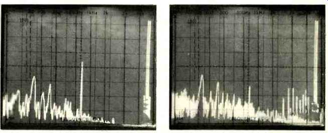
Fig. 9--IM distortion, mono, in auto-tune mode.
Fig. 10--IM distortion, stereo, in auto-tune mode.
The IHF Tuner Measurement Standards call for an IM distortion measurement commonly known as CCIF-IM. In this measurement, two tones (14 kHz and 15 kHz) are used to modulate the generator to peaks of 100 percent modulation, and the resultant "beat frequency" of 1 kHz appearing at the output is expressed as an IM distortion percentage. Our lab is now equipped to make this measurement, and these measurements were made both with manual tuning and using the AFC feature. Results are as follows:
In the "wide" i.f. mode IM in mono measured 0.016 percent when manual tuning was used and 0.16 percent when relying upon the PLL auto-lock circuit. For stereo, manual tuning brought the IM down to 0.04 percent, while 0.067 percent was obtained with the auto-lock system. The measurements were repeated for the "narrow" i.f. setting. This time, manual tuning in mono resulted in an IM reading of 0.02 percent which increased to 0.14 percent when the automatic tuning system was activated, while for stereo the readings were 0.026 percent for manual tuning and 0.058 percent for "auto tune." To further illustrate this technique, we plotted the output of the tuner on our spectrum analyzer with the two test tones applied. Fig. 9 shows the 14-kHz and 15-kHz test tones at the extreme right of the 'scope photo, while near the center we see the .(approximately) 1-kHz "difference" component. To emphasize the effect, the plots were taken with the tuner in the "auto tune" setting, where we knew that the IM components would be higher.
Interestingly, in stereo, the 1-kHz component observed (at the center of Fig. 10) is actually much lower than it was for mono, confirming the meter readings obtained earlier. however, in Fig. 10 we also see several products arising at the higher frequencies caused by different combinations of beats between multiples of the 14-kHz and 15-kHz frequencies.
The CCIF IM method does not call for inclusion of these components in the final IHF-IM reading. However, in the new IHF Amplifier Measurement Standards, such components are to be included in the IHF-IM measurement and, where applicable, we will attempt to report such IM measurements in future amplifier test reports which we are called upon to prepare for Audio.
Muting threshold as well as stereo switching threshold were both set at 16 pV (29.3 dBf) on our sample, a little high in view of the excellent quieting and low distortion characteristics of the tuner. Of course, the muting is defeatable should the user wish to search for distant, weaker signals.
Listening and Use Tests
For all our criticism of some of the test results obtained for this sample, we must admit that the tuner performed extremely well during the listening tests that followed. In our closed-circuit tests (wherein we "transmit" our own program sources via our r.f. generator to the tuner under test), A-B tests between directly amplified reproduction of some of our favorite direct-to-disc recordings and "off-the-air" pickup of the same program material disclosed little, if any, audible differences. By the same token, we could also detect no difference in sound quality when switching from the "wide" to the "narrow" i.f. modes. In real off-the-air tests, the tuner was able to pick up every station which we normally receive in our test location with excellent quieting. The multi-path indicator works well and is a true aid in proper antenna orientation, and the same LEDs, when used to determine signal strength of an incoming signal, are intelligently calibrated so that wide ranges of signal strength can be clearly interpreted.
Closed-circuit tests of the Dolby circuitry confirmed that Dolby calibration was just about perfect and, at weak signal levels, the improvement in S/N with Dolby FM is so impressive that we wonder why more stations do not avail themselves of this broadcast system, which requires no special approval by the FCC and may be adopted by any FM station in the United States.
All in all, then, here is a tuner which is well engineered and delivers quality FM reception to those who may be fortunate enough to live in an area where quality FM is in fact broadcast.
--Leonard Feldman
(Source: Audio magazine)
Also see: Proton 440 Tuner (July 1985)
McKay Dymek Model DR-33 All-Wave AM/SSB/CW Receiver (Sept. 1979)
Rotel RC-870 Preamp (Aug. 1985)
= = = =