by LEONARD FELDMAN
A Modern Switching-Circuit Decoder
HAVING previously considered the way in which a so-called "Time Division" or "switching" stereo-multiplex decoder works, it would be well to examine in detail a latter-day circuit embodying these principles. Starting with the basic concepts described last month, many manufacturers have embellished their circuits to such an extent it is often difficult to "pick out" the elements of the decoding process.
Usually, the refinements are present for two very good reasons-first, to improve performance specifications, such as separation at all frequencies, adequate residual 38- and 19-kHz rejection following demodulation and so on, and secondly, to incorporate such convenience features as automatic switching of mode (from monophonic to stereo FM) , stereo indicator lights, and the like.
A straightforward and clean design is to be found in the MPX decoder section of the Sony STR-6120 Receiver and, with the kind permission of that company, we shall use elements of that design to describe the "decoding" process in terms of an actual, currently marketed, design. Since this particular receiver is in a fairly high-priced category, its designers incorporated just about every feature that can be found in modern stereo FM circuitry, and it will therefore serve well for these illustrative purposes.
A block diagram of the circuit is shown in Fig. 1. The input signal, taken from the output of the ratio detector and without any de-emphasis applied, is first amplified by a composite amplifier stage. Outputs are taken from both the collector and the emitter of this transistor amplifier. The collector is followed by a tuned circuit, adjusted to resonate at 19 kHz (the pilot-signal frequency) which, together with a transformer tuned to the same frequency, eliminates everything in the composite signal but the desired 19 kHz and couples this signal to a 19-kHz amplifier. The 19-kHz signal developed at the collector of this stage is transformer coupled to a full-wave rectifier consisting of a pair of diodes. This portion of the circuit is shown schematically in Fig. 2. Since the pulses produced by the pair of rectifiers are not filtered, two such pulses are produced for each cycle of 19 kHz, as shown in the figure.
It is these non-sinusoidal, but fairly large-amplitude pulses which are used to trigger the mono-stereo mode switch shown at the lower left of the block diagram of Fig.. 1, and about which we shall have more to say later. The collector circuit of the next stage (38-kHz amplifier) is tuned to 38 kHz by means of a resonant tank circuit. The resulting sinusoidal 38-kHz signal is transformer coupled to a bridge-type demodulator circuit, which differs from the simple, two-diode demodulator previously analyzed, as shown in Fig. 3.
Referring back to the composite amplifier of Fig. 1, the signal derived from the emitter of that stage contains all the frequencies of the composite signal--i.e. main-channel frequencies from 50 Hz to 15,000 Hz, the 19-kHz pilot signal, stereo sideband signals in the range from 23 to 53 kHz and, if SCA (Background Music Subscriber Service) is transmitted, the frequency-modulated 67-kHz subcarrier as well.
The entire composite signal is first passed through a 19-kHz band-elimination filter, to remove that component, and then through a 67-kHz filter to eliminate frequencies associated with any possible SCA transmission.
The resultant composite signal is applied to the center tap of the secondary winding of the demodulator transformer shown in Fig. 3. By employing four diodes in a balanced-bridge arrangement, the system cancels most of the residual 38-kHz products which would otherwise be present in the simpler two-diode arrangement. Alternate conduction of upper and lower diodes (as alternate polarities of 38 kHz are applied to each end of the secondary winding) results in the detection, or sampling, of the L and R signals at their respective output lines. Note that in the block diagram of Fig. 1 we have labeled these outputs as L and .^'R, the wiggly symbol being a mathematical term meaning "approximately" --that is, approximately L only and approximately R only.
For many reasons, beginning way back in the i.f. system or at the output of the main channel ratio-detector, the "mix" between main-channel program content and sub-channel sidebands may have become unbalanced in both amplitude and phase. Unless this "mix" is in precisely the correct proportions, there will be some R in the L line and some L in the R line. How Sony compensates for this "impure" separation will be shown shortly.
---------
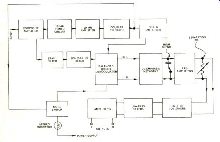
Fig. 1--Block diagram of the Sony STR-6120 stereo FM decoder circuit.
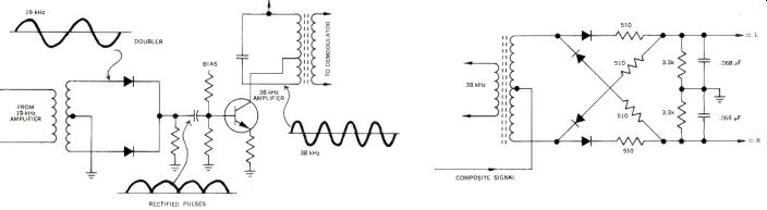
Fig. 2--Full-wave rectifier followed by tuned amplifier "doubles" the 19-kHz pilot signal to 38 kHz. Fig. 3--Balanced-bridge demodulator circuit used to recover L and R signals.
---------
You will recall that up to this point, no de-emphasis has been applied to the signal, since to have done so previously would have resulted in nearly total attenuation or elimination of the vital super-audible frequencies which are a part of the composite signal prior to stereo demodulation. That process is accomplished now, after demodulation, and because two distinct signals now exist, a de-emphasis network is required for each. The networks themselves consist of nothing more than the usual R-C network to "roll off" the high frequencies in a prescribed manner (75-microsecond time constant, just as in monophonic FM). At this point in the circuit, Sony introduces a HIGH BLEND switch which, by means of a small capacitor connected between the L and R circuits, permits the mixing together of the higher audio frequencies. Since this, in effect, ruins separation at these high frequencies, you might wonder why such a "partial stereo defeat switch" would be introduced. It can be shown that the high-frequency noise associated with stereo FM, in the presence of a weak signal, appears in opposite phase in the L and R channels. Thus, the switch is only intended to be used for such poor-reception situations. When the switch is shorted, some of the high-frequency noise of one channel cancels that in the opposite channel, albeit at the expense of high-frequency stereo separation. The philosophy here is that it is better to enjoy noise-free stereo with poor high-frequency separation than to have to listen to noisy stereo with optimum separation. As with most such niceties, the switch in a consumer-actuated control, so the listener still has the option.
The next stage, though labeled preamplifiers, really serves a more important function than just straight amplification. A schematic of this portion of the circuit is shown in Fig. 4. The resistor-potentiometer combination connecting the emitters of the L and R channels provides a form of negative feedback between the channels. You will recall that up to this point, there may be some residual L in the R channel and some R in the L channel. For purposes of illustration, let us assume that the L channel contains 0.9 L and 0.1 unwanted R, and that the converse is true of the R channel. Now, if the amount of negative feedback is such that-0.1 (0.9R + 0.1L) is introduced into the (0.9L + 0.1R) channel (10 percent feedback), the resultant signal coming out of the "L" line will be (0.9L- 0.01L + 0.1R-.09R), or, (0.89L + 0.01R).
Although we have reduced the amplitude of the desired L signal from 0.9 to 0.89, we have simultaneously reduced the undesired R content from 0.1 (10 per cent) to .01 (1 per cent. In "dB" terms, this represents an improvement from 20 dB of separation to 40 dB. It should be obvious that while all this improvement is taking place in the "L" channel, the same feedback correction is symmetrically taking place in the "R" channel. In theory, at least, proper adjustment of potentiometer in Fig. 4 should result in complete elimination of unwanted L in R and unwanted R in L. In practice, however, there are not only amplitude differences to be compensated for, but phase differences at different audio frequencies as well.
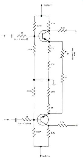
Fig. 4-Symmetrical negative-feedback circuit optimizes separation.
Only careful initial design can take care of these phase-response differences between channels and between main- and sub-channel components, so that a separation figure of 40 dB at all frequencies is rarely achieved in a practical design. A separation of 40 dB at mid -frequencies, however, is realizeable and has been noted for several of the better stereo receivers and tuners currently available. Interestingly, the FCC requires only approximately 30 dB of separation at all frequencies in the transmission process and most popular phono cartridges don't even do that well on stereo discs (though stereo tapes can do a lot better). Following the separation adjustment, the two signals are fed through a pair of emitter followers to provide a low source impedance for the low pass filters which follow. These filters remove any residual 19 kHz, 38 kHz, 57 kHz,. and 76 kHz (the latter two being harmonics of the first two) which might still be present. One or more of these frequencies, though inaudible by themselves, might beat with the local bias oscillators of tape recorders you might use to record "off the -air" stereo FM, creating unexpected whistles and squeals in your valued recordings. Accordingly, the designers of this circuit have added extra filtering to remove the last vestiges of these unwanted frequencies.
Finally, the signals are passed through a pair of conventional voltage amplifier stages, very likely to raise the signal level to match other signal inputs to this particular receiver.
--------------
(Audio magazine, 11/1969)
Also see:
How Disc Masters Are Made Today
= = = =