
MANUFACTURER'S SPECIFICATIONS
Drivers: Four 10-in. bass, six 2 1/2-in. tweeters.
Crossover Frequency: 3500 Hz.
Recommended Amplifier Power: 15 to 100 watts RMS per channel.
Frequency Response: 22 to 18,500 Hz.
Impedance: 8 ohms, nominal. Weight: 95 lbs.
Dimensions: 16 1/2 in. W x 39 in. H X 16 1/2 in. D.
Price: $299.00
The RTR 280DR is a column speaker which uses a total of ten transducers. A 10-in. extended range woofer is centrally mounted on three of the four vertical sides with a 2 1/2-in. tweeter above and another below each woofer. On the very bottom of the free-standing enclosure, a slot-loaded low bass woofer completes the column and radiates uniformly at floor level.
The fourth vertical side is painted flat black and has terminals and controls mounted in a recessed cavity. The enclosure is attractively finished in walnut and black and is definitely a speaker you would not choose to hide in a corner or out of sight for either cosmetic or acoustic reasons.
A toggle switch labeled " Normal" and "Bi-amp" is provided to allow this system to be driven by either one amplifier for full range sound or a frequency splitting bi-amplification system. Two sets of binding posts serve as woofer and tweeter connections when the toggle switch is placed in the Bi-amp position. In the " Normal" position, the woofer binding posts, also marked " Normal," serve to drive the complete system. A tweeter gain potentiometer and a resettable tweeter protective circuit breaker complete the back controls. In fairness to RTR engineering, the controls and terminology are well labeled and reasonably placed, but the purchaser is on his own from the standpoint of hookup information. A supplementary description of recommended hookup is something which is needed and we hope this is a temporary manufacturer's oversight. The use of good quality insulated terminals is commendable. Connection can be made without tools using spade lugs, tip jacks, or stripped wire of any reasonable size. This eliminates the fear of short circuiting poorly connected stranded wire if the speaker is periodically moved for cleaning purposes.
The lack of hookup instructions together with the choice of terminal configuration could be an expensive trap for the unwary Bi-amp user. In the "Bi-amp" position the two sets of terminals are electrically isolated, the woofer and tweeter each having a black and red terminal, but when the mode switch is set to "Normal," both black terminals are tied together. If the amplifiers used for bi-amplification have a common ground, it is possible to wire the speakers out of phase (such as is commonplace for 12 dB per octave crossovers) and get normal sound when the speaker is in the "Bi-amp" position. If the switch is then flipped to " Normal," one of the power amplifiers will look into a short circuit and possibly be damaged. If this speaker is used for bi-amplification, we recommend exercise of caution in hookup.

Technical Measurements
The stated impedance of the 280DR is 8 ohms nominal. Our measurements indicate that the impedance should be considered to be slightly above 4 ohms. Figure 1 is the impedance for " Normal" configuration with the two extremes of tweeter control position. Figure 2 is a plot for the Bi-amp mode with the tweeter impedance given at the two extremes of adjustment. This speaker should not be paralleled for drive from most transistor amplifiers. In view of the higher amplifier demands of this speaker, the heaviest gauge hookup wire should be used that is practical and consistent with decor.
The anechoic frequency response obtained one meter directly in front of the speaker is shown in Fig. 3 for the " Normal" switch position and the tweeter level control set to the mid position. The amplitude response is 5 dB from 40 Hz to 14 kHz. The response is non-minimum phase only near the acoustic crossover frequency of 2 kHz. The phase slope indicates the acoustic position of the woofer is about 6 inches behind the tweeter.
The "Bi-amp" response of woofer and tweeter considered separately is shown for pressure amplitude only in Fig. 4.
The range of control for the tweeter is +7 dB in the maximum position to-5dB in the minimum position referenced to the halfway position of the potentiometer on the rear of the cabinet.
The tweeter control changes the electrical damping causing some response irregularities below 4 kHz at control positions less than maximum. If this speaker is connected for bi-amplification, we recommend using the maximum tweeter position and reducing the gain in the tweeter control of the amplifier.
The frequency response deteriorates off-axis and shows interference dips at 45° due to an equal contribution of sound from the identical front and side drivers. Progressing around to 90°, the response again smooths to a similar form to that of Fig. 3.
The energy-time plot of the first millisecond of direct sound for all components from 20 Hz to 20 kHz is shown in Fig. 5.
This is the amount of time spread which an impulsive sound undergoes when reproduced through the 280DR. Because the measurement is performed at a distance of one meter in front of the grille cloth, the first arrival is due to the tweeters and comes at around 3.2 milliseconds. The impulse response is within 20 dB of its peak value for 0.25 milliseconds after the first arrival and within 30 dB for the first millisecond. No significant energy remains beyond 1.25 milliseconds of first arrival indicating a desirable lack of internal structure reverberation.

Fig. 1--Impedance for normal operation and extreme position of the tweeter
control.
Fig. 2--Impedance for bi-amp operation using woofer alone or tweeter alone with extreme positions of tweeter control.

Fig. 3--Anechoic frequency response including amplitude and phase measured
one meter on axis with one watt input.
Fig. 4--Anechoic pressure amplitude response for the bi-amp mode with woofer alone and tweeter alone
Fig. 5--Energy-time response measured one meter on axis.
The 280DR is intended for free-standing use in a room. In order to evaluate the technical performance under these conditions the speaker was placed on a rug surface in a room with a hard plaster ceiling slightly over 8 feet above the floor.
The microphone was placed one meter above the floor (slightly over three feet) and three meters (about nine feet ten inches) in front of the speaker. An energy-time measurement indicated that the first 2 milliseconds of sound arrival contained the majority of direct and floor reflected sound and that the ceiling contribution was perhaps 5 dB less than the floor reflection and somewhat less than later scatter arrivals from other portions of the room. Frequency response measurements were taken for both the first 2 milliseconds of arrival and the first 6 milliseconds of arrival which would include ceiling reflection.
There was no substantial change in the character of the spectrum for these two time-gated frequency responses. Figures 6 and 7 show the frequency response of the first 6 milliseconds of arrival for two azimuth positions at 3 meters. The zero degree curve is the on-axis response and corresponds to sitting directly in front of the speaker. The second measurement is made for a 30° off-axis position corresponding to the left channel of a stereo installation with a 60° separation angle. The data is not continued below 100 Hz because of the six millisecond time window used for this measurement. A general dip in response is noted from about 2 kHz to about 7 kHz with a top end brightness peak in the vicinity of 10 kHz then a drop off above 15 kHz. The tweeter control was placed in the same position as for the anechoic measurement of Fig. 3. Because of the radiation from three sides of the enclosure, the 280DR contributes a substantial amount of room reflected sound in any normal listening situation. Thus room coloration problems must be anticipated. The general dip in the treble region is found at all azimuth radiation angles.

Fig. 6--Frequency response for the first six milliseconds of direct sound
including floor and ceiling contributions measured three meters on axis.
Fig. 7--Frequency response for first six milliseconds of direct sound including floor and ceiling contributions measured three meters at 30° off axis.
Fig. 8--Polar energy plot.
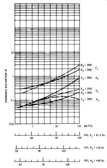
Fig. 9--Harmonic distortion of flute-type tones E1, A2, and A4 as a function
of driver power in watts and SPL one meter on axis.

Fig. 10--Intermodulation distortion using 41 Hz , and 440 Hz mixed 1:1.
The polar-energy plot is shown in Fig. 8. This is the total energy in the 20 Hz to 20 kHz range as a function of angle.
The view is that of looking down on the speaker, and this measurement is made anechoically for the first two milliseconds of arrival. The plot shows the two extreme positions of the tweeter control. There is a very clear symmetry of the direct frontal and side axis as one would expect but .which is not found near the 45° positions. If these speakers are positioned in a usual stereo configuration such that the front of the speaker is directly perpendicular to the line of centers joining them, the polar fingers at 45°, together with the interference prone frequency response at this angle, will give good stereo localization only over a narrow range of seating positions when the speakers are farther apart than 60°. The implication of this polar measurement is that you should rotate the speakers toward the listening area in order to preserve localization. The broad dispersion of sound implies that a substantial stereo effect can be expected due to room reflection.
The 280DR is stated by the manufacturer as being moderately efficient and an amplifier power of 15 watt to 100 watt is recommended. Our measurements indicate that a one watt electrical input produces a sound pressure level of 82 dB one meter on axis at 1 kHz. Even adding the contribution of the other two major axes, this must rank as a speaker which demands a lot of power. Even if you are not a hard rock enthusiast, you could readily run an amplifier into peak clipping in a moderately draped listening area if it has less than a 50 watt rating. Our experience in measuring distortion, however, makes us recommend the use of speaker fuses if a high power amplifier is used. The harmonic distortion on the 280DR is extremely low.
A flute tone E1 (41.2 Hz) at 20 watts input produced I percent E2 (second harmonic) and 1 percent A, (third harmonic). The critical mid bass remained below 0.4 percent at this same level. It was not until a power level of 100 watts at 41.2 Hz that the bass drivers became non-linear as indicated by the ratio of odd to even harmonic distortion. The sound pressure level measurement of Fig. 3 is for one of the three equal axes of radiation. The sound pressure level of 90 dB shown in Fig. 9 is calculated by adding 5 dB to take into account the contribution of all speakers in a reverberant environment.
Our undoing occurred during the testing at the 100 watt level. Even though the tone is applied for about 5 seconds duration for each component, we managed to burn out one of the woofers during test. The fault rests solely with us since the lack of sonic distortion lulled us into testing at high power. The lesson, however, is clear. Because you need a truly high power amplifier to get high sound levels, we strongly recommend fusing the speaker lines with a fast blow fuse rated no larger than 5 amps. The power level of 100 watts shown on the harmonic distortion plot is that which would be delivered to an 8 ohm resistor. Investigation of the impedance plot shows that we were in fact delivering close to 200 watts of heating power to the 280DR at maximum test level.
Intermodulation distortion was determined by using E1 and A2 at equal power ratios and measuring the modulation side bands on A4. The relative order of the sidebands indicated that the effect was more nearly due to frequency modulation than amplitude modulation. With this type of drive, a 25 watt E1 and a 25 watt A4 produce a peak drive that demands the services of a 100 watt rated amplifier. At this level the intermodulation distortion is 2.4 per cent and is composed primarily of 481 Hz, 399 Hz, and 358 Hz. Intermodulation is more prevalent than harmonic distortion, remaining at nearly 0.5 per cent at one watt input, corresponding to a quarter watt each of E1 and A4.
For the signal suppression test, 440 Hz and 3500 Hz were used with white noise mixed at an average level 20 dB higher than the tones. No signal suppression of these equivalent inner musical voices was noted when the white noise was added, even up to a noise peak voltage of 80 volts across the speaker terminals. The 280DR can handle high peak-to-average crescendos up to the capability of the most powerful amplifier without compression of inner voices.
Listening Tests
Several room positions were tried and the most listenable location was flush against a hard wall and symmetrically located on either side of a projecting fireplace. Presumably a bookshelf would serve the same acoustic purpose. In other room locations, the illusion was one of listening to more localized loudspeakers, though quite good ones. Even in the best wall position, the sound has good stereo spread but the stereo localization is not as good, since a phantom center image is not really well defined and the extreme left and right sound images are more sharply localized. The flush wall position was found to help fill in the phantom center channel.
The sound is that of slightly suppressed mid to high frequencies with a modest top end peak which accentuates a few voice sibilants. The extreme top end which might give instrumental sheen seems down somewhat, particularly when a disc such as the sparkling Shostakovich Symphony No. 15 (RCA ARD-1-0014) was played. Any high frequency tone control which simply boosts the frequencies above 1 kHz would not help this, because extreme high frequencies will start spitting before the 5 kHz region is raised sufficiently. A mid-band equalizer would be more effective if your personal choice is for stronger mid frequencies.
The 280DR has a smooth, solid bass. In moderate size rooms, the low bass is definitely present but not obtrusive. If you have any turntable rumble, this speaker will let you know should you carelessly add bass boost.
This speaker is well suited for the reproduction of massed orchestral music where absolute pinpoint localization is not altogether important, though this can be improved by rotating the speakers toward the listening area. However, the cosmetic effect of this position for these attractive enclosures leaves something to be desired. The manufacturer advises that if the units are to be placed more than 8 or 10 feet apart, a corner position is to be preferred with rotation towards the center.
Classic organ music, on the other hand, can be reproduced with great accuracy at high levels. Hard rock music which places a great demand on the 1 to 5 kHz range was not reproduced to my complete satisfaction. For example, the Cat Stevens selection, on Sheffield Vol. II, seemed to lack punch when played at the levels one usually likes to hear such pieces.
In any event, the best performance can only be obtained from the RTR 280DR by using amplifiers which are able to drive 50 or more clean watts into 4 ohms.
Overall, the speaker should be considered as very good and the $299 price tag is quite reasonable for this level of performance. For best reproduction, these speakers need to be used with high quality components and they may lead you into buying more than just a pair of speakers.
-Richard C. Heyser
Editor's Note
This is the first in a new series of speaker system reviews. While these test methods are not new, since they have appeared previously in engineering journals, they are new to these pages and should generally be compared only with the reviews following in this series. A full explanation of the test procedures used begins here.
(adapted from Audio magazine, Nov. 1973)
Also see:
Rogersound RSL 28 Loudspeaker System (Jun. 1973)
Microstatic Full-Range Loudspeaker (Jun. 1973)
Rectilinear XIa Loudspeaker System (Aug. 1973)
Dynaco A-35 Loudspeaker System (Jun. 1973)
= = = =