
MANUFACTURER'S SPECIFICATIONS
(All stated by manufacturer as minimums)
Usable (IHF) Sensitivity: 2.0 µV at any frequency.
Selectivity: 60 dB.
THD: Mono, 0.25%; stereo, 0.35% (both at 1 kHz).
S/N: 70 dB.
Image Rejection: Greater than 100 dB.
I.F. Rejection: Greater than 100 dB.
AM Rejection: 60 dB.
Capture Ratio: Less than 2.0 dB.
SCA Rejection: Inaudible.
Pilot and Sub-carrier Rejection: Greater than 50 dB.
Stereo Separation (1 kHz): 45 dB.
Dimensions: 16 in. W, 4 3/4 in. H, 15 in. D.
Price: $525.00.
Now Harman-Kardon's new Citation line is complete! The introduction of the Citation Fourteen tuner will enable Citation fans to put together a complete system, consisting of a Citation Twelve stereo power amplifier, a Citation Eleven control preamplifier, a Citation Thirteen speaker system, and this new Citation Fourteen tuner for a total of $1760.00! While the product numbering system eludes us, the product performance leaves little to be desired. The new Citation Fourteen, pictured above, includes circuit and styling innovations worthy of the Citation reputation. Just below the blacked-out dial area (which is illuminated in a soft green glow when power is applied) is a massive, horizontally mounted thumb-wheel tuning knob, knurled for easy finger spinning. The knob is vernier-coupled to a flywheel and a cylindrical dial scale which turns as the knob is turned, disclosing only a few MHz of dial spread at a time. We could swear we saw similar arrangements way back in the 1930's, but somehow, as executed by Harman-Kardon, this tuning approach is fresh, clean, and practical. The blacked out area also contains the familiar stereo indicator light, a light which becomes illuminated when the Dolby circuit is actuated, a center-of-channel tuning meter and, best of all, a quieting meter which is quite unique and differs from the usual signal-strength meter commonly found on two-meter tuners and receivers. We'll have more to say about this innovation later.
[The ESS Mk VII speaker system was promised for this issue, but unfortunately had to be put off until next month because of a lack of space. -ED.]
Below the dial area are two rotary switch knobs: one a three-position stereo noise-filter selector, the other a function switch with positions for mono, automatic mono-stereo switching and stereo-only reception. The left-hand portion of the panel (which, by the way, is machined from a chunk of 1/4 inch, solid, gold-anodized aluminum) includes linear slide controls for left and right output level, four push-push buttons for power on/off, Dolby circuit on/off, muting circuit on/off and, finally, a push button with which a built in 400 Hz tone, corresponding to 50% FM modulation, can be applied to the outputs for pre-setting tape recorder levels. A tape-out jack (in parallel with the fixed output jacks on the rear panel) completes the front panel layout.

Fig. 1--View of the back panel and interior from the rear.

Fig. 2--View from above.
The rear panel, shown in Fig. 1, includes a pair of variable outputs (level is controlled by the front panel slide controls), the fixed output jacks, horizontal and vertical 'scope connection jacks (for output signal observations if you own an oscilloscope), a quad-decoder jack (for the four-channel broadcast system of the future), a muting threshold adjustment, antenna screw terminals for 300 or 75 ohms transmission lines plus a 75 ohm coaxial connector, a switched convenience a.c. receptacle, and a line fuse.
Top view of the inside of the chassis is shown in Fig. 2.
In addition to the sealed front end there are six other printed circuit board modules. The front end features a five-gang tuning capacitor, three FET's and a bi-polar local oscillator.
The i.f. module includes 2 high gain IC's and a sealed 9-pole phase-linear LC network plus a highly linear ratio detector circuit which is the only tunable element in this section.
The quieting meter and muting circuit board contains no less than 22 NPN transistors. Rear panel muting and stereo threshold controls are associated with this PC board, as is the new type of meter mentioned earlier. This meter works just opposite to the usual signal strength meter. Its "zero" is at the extreme right and the numbers progress to the left, from 0 to 10. Were it simply a "backwards wired" meter, however, there'd be nothing much to discuss. As it is, this meter gives a direct indication of quieting, or signal-to-noise ratio. In tuning to a station, you are instructed to tune for the highest number attainable (lowest reading, if you can't help thinking from left to right). To verify this new concept, we plotted meter readings against actual measured S/N and the results are shown in Fig. 3. As you can see, the action is almost the exact inverse of the "noise" curve shown in Fig. 4, unlike most so-called signal-strength meters which generally "do their thing" almost linearly from 0 to 40 to 50 microvolts and then "hover" at maximum from that point upward in signal strength. We found, in using this tuner, that the "maximum" S/N indication is an even finer indication of correct tuning than the center-of-channel meter which is also included.
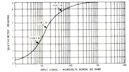
Fig. 3--Special meter reads quieting (S/N), rather than signal strength.

Fig. 4--FM performance characteristics.
The heart of the multiplex PC module is a new integrated circuit which employs phase-lock-loop circuitry for "locking on" to the incoming 19 kHz pilot signal. There are no coils to adjust for best separation, just a couple of factory pre-set resistive potentiometers. An elaborate system of pi-section filters accounts for the very excellent pilot, subcarrier, and SCA rejection characteristics of the Citation Fourteen. A partial schematic of this section of the tuner is shown in Fig. 5, to give you an idea of just how many parts can be eliminated when a well-designed IC is used in a circuit of this kind.
Other PC boards include the power supply module which contains two zener diodes and five transistors in a regulating circuit which supplies stable +15 and -15 voltages to the other modules. The output module contains a pair of transistors in a direct coupled configuration for each channel output. Supply voltage is a high 50 volts to insure extremely linear characteristics with wide signal swings.
Finally, the Dolby module contains six transistors plus an FET per channel. Its action will be described shortly.
Electrical Measurements
Because of the quality inherent in this Citation Fourteen, we took more than the usual number of measurements to give as complete a picture of performance as possible. In Fig. 4 you can see that ultimate quieting is 72 dB, a bit better than the 70 dB claimed. Mono THD (at 1 kHz) goes below 1% for an input signal strength of 8 microvolts, reaching an incredibly low figure of 0.14% at all signal levels above about 100 microvolts. It should be noted that our new Sound Technology FM Generator only guarantees internal THD of 0.1% (lower than any other FM generator available) and, as you can see, the Citation Fourteen almost calls for another advance in measuring instrumentation! (We just finished paying off the $1800.00 for the new generator at that!) An additional curve presented is that of residual noise in the stereo mode. This figure reaches an amazing 64 dB-amazing when you take into account the fact that included in the reading are any residual 19 kHz and 38 kHz components which, though extraneous, are not normally perceived as audible "noise." This additional curve is usually meaningless if taken on most tuners because of the presence of these components at the output at a level of -40 to -50 dB or so.
IHF sensitivity proved to be 2.0, as claimed but, more important, full (-1 dB) limiting was reached at 1.5 µV input and 50 dB of S/N was attained with 7 microvolts of input signal.
Figure 6 depicts stereo FM separation at all significant frequencies as well as mono and stereo THD from 50 Hz to 10 kHz. It is in the area of separation, particularly, that the new phase-lock-loop circuit pays off. Separation of better than 40 dB from 50 Hz to just over 4 kHz is something you just don't run into with more conventional multiplex decoding circuits. Of course, the phase linear i.f. system helps a great deal too. Again, with a test instrument capability of 50 dB separation, this tuner is "pushing it." Even at 15 kHz, separation still measured 30 dB.

Fig. 6--Stereo separation and mono and stereo THD versus frequency.

Fig. 7--Dolby action versus frequency at various levels.
The THD characteristics for mono and stereo, also shown in Fig. 6, are outstanding. If you've been following our last few reviews, you'll recall that stereo THD at the high end is usually quite severe (and usually not quoted by manufacturers). In the case of the H-K Citation Fourteen, stereo THD at 10 kHz is only 1.1%, with values hovering just below 0.5% over most of the useful audio range. In the case of mono, too, the 0.14% figure quoted for 1 kHz THD is not just a "best frequency" reading. Even at 50 Hz, THD was still well under 0.5% while at 10 kHz, it measured about 0.7%. All of these readings are referred to 100% modulation.
For those not familiar with Dolby noise reduction, a brief explanation is in order. The Dolby system is based upon the principle that loud music masks background noise. In other words, when the program is instantaneously loud in volume, any background hiss or noise will be "hidden" psychoacoustically. On the other hand, during quiet passages of music, our ears "home in" on the noise and it becomes annoyingly apparent. A further correct premise of Dolby is that we are most sensitive to high frequency noise. Based upon these premises, Dolby suggests that FM broadcasters employ his equipment to boost the level of high frequency programming when that level is low, but to leave it unaltered when loud passages are broadcast. To re-establish correct relative amplitudes in the tuner, it should have circuitry which plays back all frequencies uniformly when levels are loud, but progressively attenuates high frequency levels when instantaneous program levels are lowered. In the course of this attenuation, residual high frequency noise will, of course, be lowered as well, but the overall frequency response of the desired program material will be restored to "flat" if both ends of the system are reciprocals of each other.
The Dolby circuit in the Citation Fourteen, when introduced into the circuit by means of the front panel switch, provides this dynamic attenuation in accordance with the curves shown in Fig. 7. Notice that when program material is at full modulation, no such attenuation takes place. With decreasing modulation (corresponding to soft passages), attenuation becomes greater and greater, so that with only 10% modulation, attenuation at 10 kHz is of the order of 8 dB. In effect, signal-to-noise ratio has been improved by several dB at that instant of low program level. The switch on the front panel is provided, of course, since only a few stations now employ Dolby processors, and in the absence of such pre-processing, the Dolby circuit should not be used or treble will sound deficient at low program levels. (In this area, Philadelphia, I could receive several New York stations free of noise by using the Dolby mode and compensating with the amplifier treble control--or more elegantly with a Soundcraftsmen equalizer. -Ed.) We checked range of the rear panel muting control and found it to be adjustable from 30 microvolts threshold down to zero (no muting action). The stereo threshold control is variable from about 30 microvolts down to 10 microvolts.
Referring again to Fig. 4, this is just about ideal, for S/N in stereo at 10 microvolts of input signal (always worse than in mono) is about 36 dB. In our opinion, you're better off listening in mono if S/N is any poorer than that, and evidently Harman-Kardon feels the same way about it.
Listening Tests
We were delighted to see that the extra pains taken in the design of the stereo circuitry are audibly apparent. The stereo reception we were able to obtain was flawless (at least when tuned to those few stations in our area which put out a good stereo signal). We are convinced that it's not so much the great separation that accounted for this audible difference as it was the low, low distortion figures for that portion of the circuitry. Equipped with a rotator on our outdoor Yagi antenna, we found that the quieting meter actually helped orient the antenna for best reception and least multipath. This should not come as a great surprise, since one of the effects of severe multipath is reduced S/N ratio, which is readily seen on the meter. The vernier tuning method is elegant and precise--calibration was just about perfect--as it would have to be with such an expanded scale arrangement. Maximum audio output on our unit was about 3.0 volts rms for 100% modulation and we did have to lower the two slide level controls quite a bit to match the rest of our system. Some tape recorders not equipped with input level controls might have their first stages overloaded by such a large signal.
Rather than "count stations" on this tuner, we listened at greater length to only those stations which had adequate signal strength to allow the Citation Fourteen to perform optimally by setting the mute threshold control to 10 microvolts.
At that setting, 40 first-rate signals were heard and 22 of those were stereo. All were amazingly quiet (except for some "studio hum" on some) and, except for those which were loaded with--shall we politely say--poor station practice, distortion was much lower than we're used to hearing. There is one station in our area (WQXR-FM) which has Dolby equipment and so we had a chance to check that circuit in our listening tests as well. It works! We purposely lowered signal strength (by hanging on a "no-no" short piece of wire instead of an antenna) to the point where noise was just audible and threw the Dolby switch--Presto, the noise disappeared!
We understand that there is a less expensive Citation tuner available (Citation Fifteen) which omits the Dolby circuit (plus some other refinements-such as the five-gang tuning in the front end), but it seems to us that if you really want perfection in a tuner (or as near to it as the state-of-the art has come), you'd want to go "all the way" to the Citation Fourteen.
-Leonard Feldman
(Audio magazine, Dec. 1972)
Also see:
Harman/Kardon Citation Twenty-Five Preamp (Mar. 1989)
Harman/Kardon Citation 16 Basic Amplifier (Equip. Profile, Dec. 1976)
= = = =