by David Lane Josephson
ARE YOU REALLY satisfied with the quality you're getting in your live recordings? The amateur recordist's main problem seems to be selection and placement of mics for the best sound pickup. While there aren't any hard and fast rules one can follow to get professional sounding tapes, here are a few ideas about mics that should help.
What is a microphone anyway? A microphone is a sound-actuated transducer; a device which accepts sound waves (air vibrations) and changes them to electrical impulses which may be amplified and recorded. The electrical impulses, according to the accuracy of the microphone, correspond more or less to the shape of the sound waves striking the microphone. Various factors-mass of the microphone's moving parts, magnetic fields, friction sources, materials used, physical construction-all affect the final accuracy of the microphone. This degree of accuracy--no mic is perfect--determines the way any given mic should be used.
There are two basic variables in the conditions that affect the quality and accuracy of any given sound pick-up: 1) the characteristics of the microphone(s) used, and 2) the position of the microphone(s) in respect to the sound source(s). Understanding the characteristics of the various microphones available is a lot easier if one knows how they all work.
Types of Microphones
In common recording use today, there are three different types of microphones: dynamic (or moving coil), capacitor (or condenser), and velocity (or ribbon). All three types can produce high fidelity recordings in the conditions they are best suited to.
A dynamic microphone is basically a speaker in reverse. The diaphragm, a basic element of any microphone, is attached to a coil of wire. This coil is suspended by the edges of the diaphragm over and around a small permanent magnet. When sound strikes the diaphragm, it makes the coil move back and forth over the magnet, thus inducing an electrical current in the coil.
Capacitor microphones (also known as condenser microphones, after the older name for capacitors) are pressure devices like dynamics, but the means used to generate the output signal are entirely different. The diaphragm in a capacitor microphone is very similar to that of a dynamic, except that it is usually flat instead of convex. It may be either thin metal foil or metallized plastic. The diaphragm is suspended about 1/1000 of an inch from a fixed metal plate, which is insulated from the microphone case. In the conventional capacitor microphone, a polarizing voltage of between 45 and 200 V. is applied between the back plate and the diaphragm. When sound strikes the diaphragm, the spacing between it and the back plate changes, changing the capacity between them. This change from one value to another changes the current flowing through the load resistor. Since the air space between the diaphragm and the back plate represents a very high impedance, the amplifier for this type of microphone must be located inside the microphone body--or at least not more than a foot or so away. Because of the extremely high input impedance this amplifier must present to the microphone element, these amplifiers were previously exclusively tube units. Vacuum-tube capacitor microphone amplifiers have now been almost entirely replaced by field-effect-transistors (FETs) which can present as high an impedance as most any tube. These have vastly decreased the size and cost of capacitor microphones today. The one remaining problem is that of getting the polarizing voltage to the capacitor element. This has been solved recently by the use of an electret element rather than the usual capacitor unit. In the electret capacitor microphone, the diaphragm is plastic and has a static electricity charge implanted in it during manufacture. The only power supply required then is the 1.5 V. or so to power the FET. Another solution to this polarizing voltage problem in extensive use before the electret was developed for capacitor microphones (the electret principle is not new) was the r.f. excited or FM capacitor microphone. In this system, still used by some manufacturers, the varying capacitance of the microphone element is connected in the grid or base circuit of an r.f. oscillator. As the sound waves strike the diaphragm, the frequency of the oscillator is varied, producing an FM signal. This is then detected by a conventional discriminator, just like that used in FM receivers, and an audio signal is produced.
Capacitor microphones always have some amplifier circuitry inside the microphone case which must be supplied with power. Numerous techniques have evolved over the years to get this power to the electronics. Perhaps the most simple is to mount a battery directly in the case. With electret mics, all that is required is a single 1 1/2-V. penlight cell.
Conventional capacitor mics usually use two 22 1/2-V. "B" batteries in series. Another method is to simply run extra wires in the cable between the mic and the power supply to carry the power. This was common practice for tube powered capacitor mics which required filament voltage and B + for the tubes as well as polarizing voltage. The two other common methods involve simplexing the power for the mic onto the cable carrying the audio back to the power supply. The widely used system is known as "phantom" powering, where the two audio leads carry the positive side of the power and the cable shield returns the negative to the power supply.
The commonly used voltage is 48 V. The other system, still being used by some manufacturers, is the powering voltage applied directly between the two audio leads. One lead carries the positive while the other carries the negative.
While this system preserves the balanced conditions necessary for r.f.-powered mics, it can add noise and precludes the use of dynamic or velocity mics on the same mic jack since such mics would present a direct d.c. short across the power supply. This system generally operates on 12V. Velocity or ribbon microphones operate on an entirely different principle from the dynamic and capacitor units.
The diaphragm is a thin duraluminum ribbon, about a quarter of an inch wide and two to four inches long, suspended between the poles of a strong permanent magnet. When sound strikes the ribbon, it moves back and forth in the lines of flux of the magnet, cutting them and inducing an electrical current in the ribbon. The velocity or speed of the sound waves determines the output rather than the pressure. Because of the extremely low impedance (usually equal to the d.c. resistance of the ribbon, or less than 1 ohm) of the mic, a step-up transformer must be mounted in the microphone case.
Velocity mics were the mainstay of almost all commercial recording and broadcast pickups, in spite of their weight and fragility, until high quality dynamics became widely available about ten years ago. One strong cough or puff of wind can tear a velocity mic's ribbon to shreds.

Fig. 1-Dynamic microphone construction.

Fig. 2-Capacitor microphone construction.
Fig. 3-Velocity microphone construction.
Characteristics and Specifications
The first element in the characteristics or personality of a given microphone is its directional pick-up pattern. This is the relative sensitivity of the unit to sounds arriving at different angles on a horizontal plane the same as the one the microphone is in. Certain types of microphones have certain distinctive directional characteristics, but all can be modified through the use of various phase-cancellation devices.
Pressure microphones are by their nature omnidirectional. This means they pick up equally well from all directions.
Velocity microphones may be made omnidirectional by attaching an acoustical labyrinth at the back of the ribbon. This changes the velocity microphone to a pressure unit, since the ribbon is now responding to pressure differences and can be pushed only toward the back of the microphone case.
Pressure microphones may be made unidirectional, or tending to pick up from the front only, by the addition of tubes and ports from the diaphragm to the rear of the mic case. In a simplified way, this produces a unidirectional effect merely by cancelling the sound waves arriving at the rear. Velocity microphones may be made into unidirectional units by dividing the ribbon into two sections and converting one section to omnidirectional as described above. The remaining half of the ribbon operates as a velocity unit. When a sound wave arrives from the rear of the microphone, it reaches the velocity section at the same time as it reaches the pressure section. Because the velocity section produces a negative voltage (because the ribbon is being pushed toward the front of the case) and the pressure section produces a positive voltage (because any sound striking the pressure unit will produce a positive signal), the two voltages, being equal and opposite, will cancel each other out and the net output will be zero. In capacitor microphones, the unidirectional pattern may be produced by either of the ways described above; there may be two elements, one for the rear and one for the front, or there may be just one element with tubes and ports to the back of the microphone. Because the actual directional pattern of most unidirectional microphones is not truly one-directional but rather heart-shaped, unidirectional mics may also be referred to as cardioid mics.
Even the best unidirectional microphone still has quite a bit of pick-up from the sides. This is sometimes advantageous, but there are times, such as the pick-up of a single person or group from a great distance, when a more selective pick-up is desired. This, too, may be accomplished in a number of ways. The first idea was to place an omnidirectional pressure unit in the focus of a parabolic reflector. This produces a pick-up angle of about 80°, somewhat better than the 180° or so produced by a good, unidirectional mic. Perhaps the most practical super-directional microphone, and today the most common, is the inline or interference mic. This uses a standard omnidirectional pressure mic at the end of a long single tube with slots in it. The principle of operation is that sound arriving from the rear of the mic is going to take longer to reach the diaphragm than sound arriving from the front. Since the sound from the rear is going to go in the front just as much as the sides, all of these sound waves will be reaching the diaphragm at different times, even though originating from the same sound wave. They produce a cancelling effect, and the net output for sounds arriving from the sides and rear will be nearly zero. The angle of pickup for this type of mic is between 40 and 80 degrees, but is free from the resonance effects common to parabolic mics.
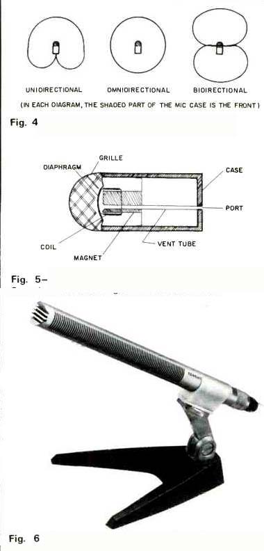
Fig. 4--Microphone pick-up patterns.
Fig. 5--Typical unidirectional microphone construction. Sound waves arriving from the rear of mic enter the port and reach the diaphragm through the vent tube at the same time the rest of sound wave reaches the front of the diaphragm. Sound from the vent tube pushes the diaphragm out, while sound from the front pushes the diaphragm in, resulting in no net movement.
Fig. 6--A capacitor version of the inline super-directional mic, the Sennheiser MKH 415, shown on a desk stand.
The last common microphone pick-up pattern is bidirectional or figure-eight. Velocity microphones, by virtue of the physical plane of the ribbon itself, are inherently bidirectional. Most capacitor microphones can be made bidirectional by the use of two separate microphone elements connected out of phase with each other.
All three directional characteristics may be combined in one microphone, sometimes known as a poly-directional unit.
This may be either a capacitor or velocity mic. In a capacitor mic, two omnidirectional elements are used back-to-back.
For an omnidirectional pickup, only one element is switched in. A unidirectional pattern may be had by connecting one element at a different phase from the other, by changing the polarity of one element's polarizing voltage. A bidirectional pick-up is made by connecting the two elements out of phase with each other. Typical poly-directional capacitor microphones are the Neumann U-87 and KM-86 (shown), the PML TC-4V and the AKG C-412. All of these pattern changes require no mechanical alterations to the microphone at all.
A velocity mic may be made poly-directional by dividing it into two sections as described in the unidirectional section above. If the acoustical labyrinth for the pressure section of the unidirectional pattern is provided with an adjustable flap over a hole drilled in it, the pressure section may be opened and converted back to a velocity section and its normal bidirectional pickup. If the flap is closed, the unit becomes unidirectional, and if the velocity section is disconnected, only the pressure section is used and an omnidirectional pattern results.
Microphones are available which produce a full stereo or quadraphonic pickup with one single mic. These units usually contain two or four unidirectional elements in a single case.
Typical of the stereo variety are the Neumann SM-69 FET and the AKG C-24. Bang & Olufsen some years ago came out with a stereo mic using two small velocity units in the same case. This was distributed in the U.S. by Dynaco and may still be available on the used market. Neumann has recently announced a quadraphonic microphone producing a complete quadraphonic signal with one mic unit. This mic, the QM-69, contains four separate unidirectional capacitor mic elements in a case very similar to the SM-69 FET. The four outputs are available at the power supply.
Frequency response is the tonal accuracy of any given audio equipment. In microphones, this means the relative voltage output across a wide band of frequencies for the same sound input with respect to a level at a set mid-band frequency (usually 1,000 Hz). As with all other audio gear, a frequency response rating of, say, 50-15,000 Hz is meaningless unless a specific range of tolerance (i.e. plus or minus so many dB within the range) from the level at the reference frequency is mentioned. Theoretically, one could say that any microphone would have a frequency response of 50-15,000 Hz-but the difference in output between a 15,000 Hz signal and the reference (1,000 Hz) might be as much as 60 dB. The main thing a recordist must be aware of in selecting a microphone from frequency response figures is the smoothness of the response between the numerical limits. For instance, two microphones might be rated as having a response of 20-18,000 Hz± 2 dB, but one would sound far better than the other.
Figure 8 shows why. Some microphone manufacturers have taken to supplying individually run frequency response curves for each microphone shipped. In most cases, however, the average response (a curve of a typical unit, taken off the assembly line) will give a fair indication of the flatness of a given model of mic. Sometimes these curves are included in the spec sheets for new mics.
Proximity effect is the extreme accentuation (boosting) of lower frequencies (below 200 Hz) as the sound source moves closer to the microphone. Sometimes this effect is desired, as it imparts a filling, radio-announcer quality to the voice being miked--but it definitely is not an advantage for accurate pick-up of non-voice signals. Proximity effect is much more pronounced with unidirectional mics-and because of this, many have bass rolloff switches to compensate for this accentuation. Omnidirectional mics are relatively free of this phenomenon until the sound source comes to within three inches of the microphone grille. Velocity mics are extremely sensitive to proximity and begin to show bass accentuation when the sound comes any closer than two feet. Proximity effects in conventional unidirectional mics are primarily caused by sensitivity to extreme pressure differences produced by close low-frequency sources. This problem has been suppressed to some extent by using a series of tubes and ports, one for each band of frequencies, or one large tube from the rear of the diaphragm with a continuous series of slots producing a theoretically resonance-free tube and port system. Electro-Voice calls these methods Variable-D and Continuously Variable D, respectively.
Perhaps the most misunderstood microphone characteristic is distortion. Partly because there are no accepted standards for measuring all types of distortion to be found in pickup units such as microphones, this aspect of a microphone's specifications usually goes unwritten. The most common form of microphone distortion is poor transient response. Transient response time is the time taken for a microphone's output to rise to 90 percent of its peak value when a pulse of d.c. is applied to it as sound. Most capacitor mics take around 15 microseconds-dynamic mics usually take around 40 µsec. Velocity mics are somewhere in between the two. This may help explain the characteristic "clean capacitor sound" most capacitor mics have.
Some capacitor mics are rated with a percentage distortion figure for a given sound pressure level (SPL). This is the distortion of the mic amplifier only when fed with a signal that approximates the level of a signal put out by the element at that SPL.

Fig. 7--A typical poly-directional capacitor mic, the Neumann KM-86.' Pick-up
pattern may be switched to omni-, bi-, or uni-directional. A 10-dB attenuator
switch is provided to prevent overloading distortion in high sound-pressure-level
pick-up situations.
Fig. 8--Comparison between two microphones with the same numerical frequency response specification: 2018,000 Hz, ± 2 dB. Mic A exhibits a very smooth response within those limits, having no sharp resonances or dips. Mic B has a very sharp resonance at 5 kHz and a 2 dB dip at 180 Hz. If used with a PA system, mic B would be much more prone to feedback, which would occur at 5 kHz.
Fig. 9--Frequency response of a typical unidirectional dynamic microphone with sound source at one inch and two feet.
The construction and circuitry of any microphone determine how noisy it is. Noise may be of any number of kinds--wind noise, breath pops and hisses (sibilance), handling noise or electronic noise. In dealing with various external noise sources, it is well to remember that any movement of the diaphragm in a microphone is caused by one condition: an instantaneous difference in the pressure between the front and back of the diaphragm. When both sides of the diaphragm have equal pressure on them, the diaphragm cannot move. Wind and breath noises are caused by direct air pressure changes between the front and the back. Both may be reduced to a great extent with windscreens, structures of plastic foam or rigid frameworks covered with cloth. These windscreens simply resist rapid changes in air pressure by requiring that the air slow down before reaching the mic itself. Some mics are inherently less wind and pop sensitive than others due to the inclusion of windscreens in the microphone itself or the particular mic's design. Omnidirectional mics tend to be less sensitive to wind and pop noises--primarily because the sealed air space behind the diaphragm acts to oppose any violent changes in air pressure. Unidirectional mics are more sensitive to noise of this sort, since the only opposition to diaphragm movement are the ducts and ports leading to the rear of the microphone. Handling noises are basically a function of the internal design of the microphone. If the microphone element is mounted directly to the case, with no shock mounting, vibrations and noises originating on the case will be much more easily transmitted to the diaphragm than if it were isolated from the case. Electro-Voice, among others, has developed a mic-within-a-mic design, covering an ordinary mic (usually an omnidirectional dynamic) with foam rubber and installing it in another case. This seems to be very effective in reducing case and handling noises.
Sibilance is a hard hissing noise, often with distortion and quite annoying harmonics, that appears in the output when some microphones are spoken into with "S" or "Z" sounds. Some people have extremely sibilant voices, which will produce this type of distortion with any type of mic--while others will not sound sibilant at all. Most sibilance problems can be eliminated by installing a windscreen and/or speaking across the microphone rather than into it.
Electronic noise is almost entirely limited to capacitor microphones and is caused by noise in the capacitor microphone element, or, more commonly, in the very high impedance and low level amplifier circuitry.
Impedance is the ohmic value of load which, when placed across a microphone output, will result in the most efficient transfer of power from the microphone to the load. Common figures for microphone impedance are 50, 150-200-250, and "high" (around 50,000) ohms. Most older home tape machines using vacuum tubes are meant for high impedance mics, and most current solid-state gear should be used with low impedance mics. The main operational difference between low and high impedance mics is in the length of cable that may be used. Up to two or three thousand feet of cable may be used with low impedance mics, but if high impedance mics are used, the high frequency response (above about 5 kHz) drops off drastically as the cable is made longer than 20 feet. This is because the cable acts as a shunt capacitor across the microphone. High impedance cables also pick up considerably more hum and noise than do low impedance ones.
Low impedance mics are usually supplied in a "balanced" configuration. Technically, this means that each side of the output (three wires are used, two signal and one ground) has an equal impedance to ground as the other lead. For instance, the impedance from one lead of a 200-ohm balanced mic to ground would be 100 ohms. The impedance from one lead to the other would be 200 ohms. The advantage to going to all this "balance" trouble is that one signal conductor, being the equal and opposite of the other, will be 180° reversed in phase. When an extraneous signal is picked up by the cable, the common mode rejection that occurs in the amplifier cancels the noise out. Most, if not all, professional recording and broadcast installations used 150-250 ohm balanced mics exclusively. When the microphone matches the equipment in impedance, then there is no mismatch. A low impedance microphone may be used with high impedance equipment at a sacrifice in signal level, but a high impedance mic should never be used with low impedance gear, or overloading, distortion and level loss will result.
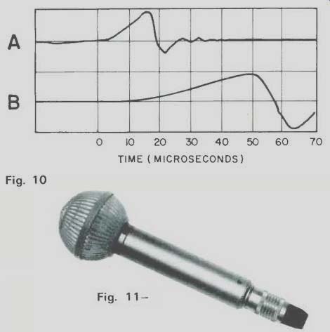
Fig. 10--Comparison of transient response time between two microphones.
Mic A is a good quality capacitor mic, while mic B is a good quality dynamic.
Note that A takes about 15 µS to reach 90 percent of its peak output, while
B takes 40 µS to reach 90 percent, with both having the same d.c. pulse
input.
Fig. 11--Rigid frame and cloth windscreen on a Sennheiser MD-211 omnidirectional dynamic mic.
It has been this writer's experience that in microphones, if in nothing else in audio, the old adage of "you get what you pay for" applies almost universally. The market in this country is crammed with just about every conceivable type, style, color, and brand name of microphone possible. There are a few units which appear to be worth much more than their price and a few that are definitely overpriced.
Used microphones can present the best value, as mics which have been used by professionals can sometimes be bought at less than half their original selling price. Microphones that come with tape recorders are too often poor quality, and, in fact, most home decks and all professional studio machines now come without mics.
Part two of this article will deal with how these microphones can best be positioned and mounted for accurate and pleasing stereo recording.
(Audio magazine, Dec. 1973)
Also see:
Microphones Vital Link in the Recording Chain--Part 2 (Jul. 1974)
A Microphone Primer: Basic Construction, Performance, and Applications (Dec. 1972)
A Microphone Primer: Conclusion (Feb. 1973)
Mike Technique and Sound Effects (Dec. 1974)
Recording in 2 and 4 Channels (Dec. 1973)
Electro-Voice microphones (Jan. 1973)
= = = =